Advertisement
Quick Links
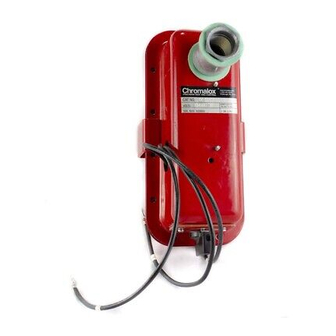
DS-50600, STAR-GF, STAR-TIP and STAR-TG Kits
For Adding Optional Kits to STAR Radiant Heaters
Model DS50600
ELECTRIC SHOCK HAZARD. Disconnect all power
to heater before installing or servicing kit(s).
Failure to do so could result in personal injury or
property damage. Kit(s) must be installed by a
qualified person in accordance with the National
Electrical Code, NFPA 70.
To use this instruction sheet from Table 1 select the Installation
Instructions by matching the Kit Model to the Heater Model. If a
match does not exist consult Factory.
Table 1
Kit Model
DS-50600
DS-50600
STAR-GF
STAR-TIP
STAR-TG
© 2008 Chromalox, Inc.
Chromalox
Used with Heater Model
Fixed STAR-06A and STAR-14A
Portable STAR-06A and STAR-14A
All Fixed STAR
Portable STAR-06A and STAR-14A
Portable STAR-06A and STAR-14A
®
Model STAR-TIP
STAR-TG
Always check to make certain the voltage rating of the kit
matches the voltage rating of the heater (See Nameplates).
GENERAL
The kits are add-on options to STAR Radiant Heaters. The
installation and renewal parts identification for the heater is cov-
ered in the instruction sheet provided with the heater. SAVE
BOTH COPIES OF THE INSTRUCTION SHEET.
Kit Function
Adds Integral Disconnect Switch
Adds Integral Disconnect Switch
Adds Wall Mounted Ground Fault Sensor
Adds Tip Over Shut Down
Adds Tip Over Shut Down with Ground Fault Sensor
4
DIVISION
SECTION
SALES
(Supersedes PG436-1)
REFERENCE
JUNE, 2010
DATE
STAR-GF
Installation Instructions
See Page 2
See Page 3
See Page 4
See Page 5
See Pages 5 and 6
VTS
PG436-2
161-304901-004
Wiring Diagram
Fig. 1
Fig. 1
Fig. 2
Fig. 3
Fig. 4
Advertisement

Related Manuals for Chromalox DS-50600


Summary of Contents for Chromalox DS-50600
- Page 1 Chromalox DS-50600, STAR-GF, STAR-TIP and STAR-TG Kits For Adding Optional Kits to STAR Radiant Heaters Model DS50600 ELECTRIC SHOCK HAZARD. Disconnect all power to heater before installing or servicing kit(s). Failure to do so could result in personal injury or property damage.
-
Page 2: Installation Instructions
1. Addition of the disconnect switch assy must be done by a qualified electrician. 2. The disconnect switch kit includes the following parts. Verify that all parts are included, if not, contact the Chromalox Service Dept. (1)Disconnect Switch Assy (2)Mounting Bracket (Not Used) (3)Hardware Kit: (Not Used) Two 3/8”... - Page 3 1. Addition of the disconnect switch assy must be done by a qualified electrician. 2. The disconnect switch kit includes the following parts. Verify that all parts are included, if not, contact the Chromalox Service Dept. (1)Disconnect Switch Assy (2)Mounting Bracket (3)Hardware Kit: Two 3/8”...
-
Page 4: Maintenance
6. The ground fault sensor has been factory set at .03 Amps, DO NOT CHANGE THE SETTING. The Chromalox STAR-GF ground fault sensor provides a reli- able and cost effective method for sensing ground faults. The pur- pose is to monitor for ground faults, sense potential heater failure symptoms and to protect equipment. - Page 5 1. Addition of the tip over switch assy must be done by a qualified electrician. 2. The tip over switch assy includes the following parts. Verify that all parts are included, if not, contact the Chromalox Service Dept. (1)Tip Over Switch Assy...
- Page 6 The Chromalox STAR-TG tip over cutout with ground fault sensor provides a reliable and cost effective method for sensing ground faults and to shut off the heater in case of tip-over. The pur- pose of the ground fault control is to monitor for ground faults, sense potential heater failure symptoms and to protect equipment.
- Page 7 For applicable wiring diagram see Table 1 TERMINAL BLOCK GRN L1 L2 L3 DISCONNECT SWITCH Fig. 1 GROUND FAULT MONITOR SUPPLY TO TERMINALS INSIDE HEATER JUNCTION BOX POWER LEADS MUST PASS THROUGH CURRENT TRANSFORMER POSITION OF GROUND FAULT MONITOR PRI. SIDE TRANSFORMER CONNECTION: 208V = BLK AND RED 240V = BLK AND ORG 277V = BLK AND BRN...
- Page 8 STAR-TIP-4 STAR-TIP-7 STAR-TIP-6 STAR-TG-8 STAR-TG-2 STAR-TG-3 STAR-TG-4 STAR-TG-7 STAR-TG-6 Please refer to the Chromalox limited warranty applicable to this product at http://www.chromalox.com/customer-service/policies/termsofsale.aspx. RENEWAL PARTS IDENTIFICATION “U” Shaped Term. Block Term. Block Clamp Cont. Sect. End. Sect. 303-052241-002 303-052241-001 292-046123-001 024-052539-001 072-306110-008 Limited Warranty: 2150 N.