
Related Manuals for Acer Aspire M3600


Summary of Contents for Acer Aspire M3600
- Page 1 Aspire M3600/M5600 AcerPower M461/S461 Service Guide Service guide files and updates are available on the AIPG/CSD web; for more information, please refer to http://csd.acer.com.tw PRINTED IN TAIWAN...
-
Page 2: Revision History
Revision History Please refer to the table below for the updates made on Aspire M3600/M5600 and AcerPower M461/S461 service guide. Date Chapter Updates... - Page 3 Copyright Copyright © 2006 by Acer Incorporated. All rights reserved. No part of this publication may be reproduced, transmitted, transcribed, stored in a retrieval system, or translated into any language or computer language, in any form or by any means, electronic, mechanical, magnetic, optical, chemical, manual or otherwise, without the prior written permission of Acer Incorporated.
- Page 4 Conventions The following conventions are used in this manual: SCREEN MESSAGES NOTE WARNING CAUTION IMPORTANT Denotes actual messages that appear on screen. Gives bits and pieces of additional information related to the current topic. Alerts you to any damage that might result from doing or not doing specific actions.
- Page 5 DIFFERENT part number code to those given in the FRU list of this printed Service Guide. You MUST use the list provided by your regional Acer office to order FRU parts for repair and service of customer machines.
-
Page 7: Table Of Contents
Chapter 1 System Specifications 1 Features 1 Mainboard Placement 4 Block Diagram 6 Aspire M3600/M5600 Front Panel 7 Aspire M3600/M5600 Rear Panel 9 AcerPower M461 Front Panel 10 AcerPower M461 Rear Panel 11 System Peripherals 12 Acer eRecovery 14 Acer disc-to-disc recovery 16... -
Page 9: Chapter 1 System Specifications
System Specifications Features Processor Socket Type : Intel Socket T LGA 775 pin Processor Type : Intel Conroe FSB 800/1066 MHz Chipset Intel 946GZ+ICH7DH Form Factor : Mirco ATX Size (Max.) : 244mm x 244mm Memory Memory Type : DDRII 1.8V unbuffered SDRAM module support No. -
Page 10: Ieee 1394
Audio Audio Type : HD Codec Audio Channel : 7.1 channel Audio Controller /Codec : Realtek ALC888 Support SPDIF out Audio Connectors/Headers: Rear 6 jack follow HD audio definition Microphone In Headphone Out S/PDIF out header Support front panel audio header Add HD de-pop CKT AUX-In Type : Intel 82573L (Vidalia) PCI-E Giga LAN... -
Page 11: Power Supply
I/O Connector Controller : Super I/O ITE 8718 Rear I/O Connector 1 PS/2 Keyboard Port, 1 PS/2 Mouse Port 1 Parallel Port, 1 Serial Port 1 D-sub VGA Port 1 LAN Port 4 USB Ports 7.1 channel phone jack 1 6 pin 1394 port Onboard Connector 1 CPU socket 2 Memory slots... -
Page 12: Mainboard Placement
Mainboard Placement CPU Socket CPU_FAN1 DIMM1~2 FDD1 ATX1 IDE1 BIOS_WP SATA1~4 PANEL1 CLR_CMOS1 USB3~4 1394A1 COM2 SPDIF AUDIO2 Name LGA775 socket for Intel Core 4/Celeron D CPUs CPU cooling fan connector DDR2 240 pin SDRAM slots Floppy diskette drive connector Standard 24pin ATX power connector Primary IDE channel BIOS flash protect jumper... - Page 13 CD_IN1 PCI1~2 PCIEX1 PCIEX16 SYS_FAN1 R_USB ATX12V1 Chapter 1 Name Analog audio input connector 32 bit add-on card slot PCI Express x1 slot PCI Express x16 slot System fan connector Front Panel USB header Auxiliary 4pin power connector Description...
-
Page 14: Block Diagram
Block Diagram DEVICE IDSEL INT# REQ# GNT# PCI1 C/D/E/F PREQ-0 PGNT-0 PCI2 D/E/F/G PREQ-1 PGNT-1 1394 PREQ-2 PGNT-2 BW : 4.1GB/s @ FSB : 533MHz & Freq : 133MHz BW : 6.4GB/s @ FSB : 800MHz & Freq : 200MHz Analong Display VGA (G only) RAMDAC: 400MHz... -
Page 15: Aspire M3600/M5600 Front Panel
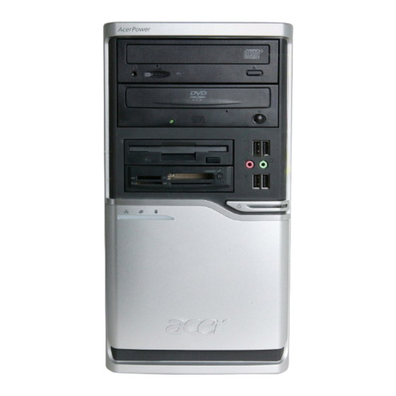
Aspire M3600/M5600 Front Panel The computer’s front panel consists of the following: Label Chapter 1 Description Optical drive Slide door/ Floppy disk drive... - Page 16 Label Description LAN LED HDD LED Power Button USB ports MIC phone Speaker out Chapter 1...
-
Page 17: Aspire M3600/M5600 Rear Panel
Aspire M3600/M5600 Rear Panel 6 audio jacks USB ports CRT/LCD port HDMI port PS/2 mouse connector SPDIF bracket Recovery switch holder Chapter 1 Description Description LAN port 1394 port Parallel port PS/2 keyboard connector Power cord port SPDIF port Lock handle... -
Page 18: Acerpower M461 Front Panel
AcerPower M461 Front Panel Label Description Power-Button USB ports Microphone-in & Speaker-out/Line-out Port Optical drive eject button Optical drive Indicators Card reader Chapter 1... -
Page 19: Acerpower M461 Rear Panel
AcerPower M461 Rear Panel Description Power cord socket Fan aperture PS/2 mouse connector Printer connector USB 2.0 ports Microphone jack Line-in jack Chapter 1 Description Description Description Voltage selector switch PS/2 keyboard connector Serial port Monitor connector RJ-45 Ethernet connector Line-out Jack Extension card slots... -
Page 20: System Peripherals
System Peripherals The Aspire S Series computer consist of the system itself, and system peripherals, like a mouse, keyboard and a set of speakers (optional). This section provides a brief description of the basic system peripherals. Mouse (PS/2 or USB, manufacturing option) The included mouse is a standard two-button wheel mouse. - Page 21 Speakers For systems bundled with speakers, before powering on the system, connect the speaker cable to the audio out (external speaker) port on the back panel of the system. For more detailed information about the speakers, please refer to the included operating instructions. NOTE: speakers are optional and the appearance might be different depending on the actual product.
-
Page 22: Acer Erecovery
Acer eRecovery Acer eRecovery is a tool to quickly backup and restore the system. Users can create and save a backup of the current system configuration to hard drive, CD, or DVD. Acer eRecovery consists of the following functions: Create backup... -
Page 23: Change Password
In the Recovery settings window, select Reinstall applications/drivers and click Next. Select the desired driver/application and follow the instructions on screen to re-install. At first launch, Acer eRecovery prepares all the needed software and may take few seconds to bring up the software content window. -
Page 24: Acer Disc-To-Disc Recovery
It is important to back up all data files before you use this option. Restart the system. While the Acer logo is showing, press <Alt>+<F10> at the same time to enter the recovery process. The message "The system has password protection. Please enter 000000:" is displayed. -
Page 25: Hardware Specifications And Configurations
Hardware Specifications and Configurations Processor Item Type Socket Speed BIOS Item BIOS code programmer BIOS version BIOS ROM type BIOS ROM size BIOS ROM package Support protocol Boot from CD-ROM feature Support to LS-120 FDD drive Support to BIOS boot block feature NOTE: The BIOS can be overwritten/upgraded by using the flash utility. - Page 26 System Memory Item Memory slot number Support memory size per socket Support maximum memory size Support memory type Support memory interface Support memory voltage Support memory module package Support to parity check feature Support to Error Correction Code (ECC) feature Memory module combinations NOTE: Dual channel should be enabled always when plug-in 2 same memory size DDRII memory module.
- Page 27 Audio Interface Item Mono or stereo Resolution Compatibility Music synthesizer Sampling rate MPU-401 UART support Microphone jack Headphone jack IDE Interface Item IDE controller IDE controller resident bus Number of IDE channel Support IDE interface Support bootable CD-ROM Floppy disk drive Interface Item Floppy disk drive controller Floppy disk drive controller resident...
- Page 28 Parallel Port Item Parallel port controller Parallel port controller resident bus Number of parallel ports Support ECP/EPP Connector type Parallel port function control Serial Port Item Serial port controller Serial port controller resident bus Number of serial port 16550 UART support Connector type Features USB Port...
-
Page 29: Power Management
Power Management Devices USB Keyboard Modem (Ring) Chapter 1 (Suspend to (Idle) RAM) Enabled Enabled Disabled Disabled Disabled Enabled Disabled Disabled (Suspend to (Shut Down) DIsk) Disabled Disabled Disabled Disabled Disabled Disabled... -
Page 30: Power Management Function (Acpi Support Function)
Power Management Function (ACPI support function) Device Standby Mode Independent power management timer for hard disk drive devices (0-15 minutes, time step=1 minute). Hard disk drive goes into Standby mode (for ATA standard interface). Disable V-sync to control the VESA DPMS monitor. Resume method: device activated (Keyboard for DOS, keyboard &... -
Page 31: Chapter 2System Utilities
System Utilities About the Setup Utility The computer uses the latest Award BIOS with support for Windows Plug and Play. The CMOS chip on the main board contains the ROM setup instructions for configuring the main board BIOS. The BIOS Setup Utility displays the system’s configuration status and provides you with options to set system parameters. -
Page 32: Entering The Setup Utility
Entering the Setup Utility When you power on the system, BIOS enters the Power-On Self-Test (POST) routines. POST is a series of built-in diagnostics performed by the BIOS. After the POST routines are completed, the following message appears: Press DEL to enter SETUP Press the delete key to have access to the BIOS Setup Utility. -
Page 33: Product Information
Product Information This option displays basic information about the system. Product Name System S/N Main Board ID Main Board S/N System BIOS Version SMBIOS Version BIOS Release Date : Move Enter: Select +/-/PU/PD:Value F10:Save ESC:Exit F1: General Help Product Names: Displays the model name of your system. System S/N: Displays your system’s serial number. -
Page 34: Standard Cmos Features
Standard CMOS Features Select Standard CMOS Features from the main menu to configure some basic parameters in your system. Date (mm:dd:yy) Time (hh:mm:ss) IDE Channel 0 Master IDE Channel 0 Slave IDE Channel 1 Master IDE Channel 1 Slave IDE Channel 2 Master IDE Channel 2 Slave IDE Channel 3 Master IDE Channel 3 Slave... - Page 35 IDE HDD Auto-Detection: Press <Enter> while this item is highlighted to prompt the Setup Utility to automatically detect and configure an IDE device on the IDE channel. NOTE: Press <Enter> while this item is highlighted to prompt the Setup Utility to automatically detect and configure an IDE device on the IDE channel.
-
Page 36: Advanced Bios Features
Advanced BIOS Features The following screen shows the Advanced BIOS Features. CPU Feature Hard Disk Boot Priority Virus Warning CPU L1 & L2 Cache CPU L3 Cache Quick Power On Self Test First Boot Device Second Boot Device Third Boot Device Boot Other Device Boot Up NumLock Status Gate A20 Option... - Page 37 enters auto thermal mode. Thermal Management (Thermal Monitor 1): This item displays CPU’s temperature and enables you to set a safe temperature to Prescott CPU. TM2 Bus Ratio (12X): This item represents the frequency (bus ratio) of the throttled performance state that will be initiated when the on-die sensor goes from not hot to hot. TMS Bus VID (1.2000V): This item represents the voltage of the throttled performance state that will be initiated when the on-die sensor goes from not hot to hot.
- Page 38 Boot Up NumLock Status (On): This item defines if the keyboard NumLock key is active when your system is started. Gate A20 Option (Fast): This item defined how the system handles legacy software that was written for an earlier generation of processors. Leave this item at the default value. Typematic Rate Setting (Disabled): If this item is enabled, you can use the following two items to set the typematic rate and the typematic delay settings for your keyboard.
-
Page 39: Advanced Chipset Features
Advanced Chipset Features These items define critical timing parameters of the main board. You should leave the items on this page at their default values unless you are very familiar with the technical specifications of your system hardware. If you change the values incorrectly, you may introduce fatal errors or recurring instability into your system. Phoenix-AwardBIOS CMOS Setup Utility System BIOS Cacheable Video BIOS Cacheable... - Page 40 PCI Express Root Port Func (Press Enter): Scroll to this item and press <Enter> to view the following screen. Phoenix-AwardBIOS CMOS Setup Utility PCI Express Port 1 PCI Express Port 2 PCI Express Port 3 PCI Express Port 4 PCI Express Port 5 PCI Express Port 6 PCI-E Compliancy Mode : Move Enter: Select +/-/PU/PD:Value F10:Save ESC:Exit F1: General Help...
-
Page 41: Integrated Peripherals
Integrated Peripherals These options display items that define the operation of peripheral components on the system’s input/output ports. OnChip IDE Device Onboard Device SuperIO Device : Move Enter: Select +/-/PU/PD:Value F10:Save ESC:Exit F1: General Help F5:Previous Values OnChip IDE Device (Press Enter): Scroll to this item and press <Enter> to view the following screen. - Page 42 IDE DMA transfer access (Enabled): This item allows you to enable the transfer access of the IDE DMA then burst onto the PCI bus and nonburstable transactions do not. OnChip Primary/Secondary PCI IDE (Enabled): Use these items to enable or disable the PCI IDE channels that are integrated on the main board.
- Page 43 Super IO Device (Press Enter): Scroll to this item and press <Enter> to view the following screen. Onboard Serial Port 1 Onboard Serial Port 2 Onboard Parallel Port Parallel Port Mode ECP Mode Use DMA CIR Port Address CIR Port IRQ : Move Enter: Select +/-/PU/PD:Value F10:Save ESC:Exit F1: General Help Onboard FDC Controller (Enabled): Select Enabled if your system has a floppy disk controller (FDC) installed on the main board.
-
Page 44: Power Management Setup
Power Management Setup This option lets you control system power management. The system has various power-saving modes including powering down the hard disk, turning off the video, suspending on RAM, and software power down that allows the system to be automatically resumed by certain events. PCI Express PM Function ACPI Function ACPI Suspend Type... - Page 45 the power button down for four seconds to cause a software power down. Resume by PCI PME (Enabled): This item specifies whether the system will be awakened from power-saving modes when activity or input signal of the specified hardware peripheral or component is detected.
-
Page 46: Pnp/Pci Configurations
PnP/PCI Configurations This options configure how PnP (Plug and Play) and PCI expansion cards operate in your system. Both the ISA and PCI buses on the main board use system IRQs (Interrupt ReQuests) and DMAs (Direct Memory Access). You must set the IRQ and DMA assignments correctly through the PnP/PCI Configurations Setup utility for the main board to work properly. -
Page 47: Pc Health Status
PC Health Status On the main boards that support hardware monitoring, this item lets you monitor the parameters for critical voltages, temperatures, and fan speeds. Smart Fan Control CPU Warning Temperature [70°C/158°F] Vcore +3.3V +12V 5V SB Current CPU Temperature Current System Temperature Current CPU fan Speed Current System fan Speed... -
Page 48: Frequency Control
Frequency Control This item enables you to set the clock speed and system bus for your system. The clock speed and system bus are determined by the kind of processor you have installed in your system. CPU Clock Ratio : Move Enter: Select +/-/PU/PD:Value F10:Save ESC:Exit F1: General Help CPU Clock Ratio (25X): Enables you to set the CPU clock. -
Page 49: Load Optimized Defaults Option
Load Fail-Safe Defaults Option This option opens a dialog box that lets you install fail-safe defaults to all appropriate items in the Setup Utility: Press <Y> and the <Enter> to install the defaults. Press <N> and then <Enter> to not install the defaults. The Fail-Safe defaults place no great demands on the system and are generally stable. -
Page 50: Chapter 3 Machine Disassembly And Replacement
Machine Disassembly and Replacement To disassemble the computer, you need the following tools: Wrist grounding strap and conductive mat for preventing electrostatic discharge. Wire cutter. Phillips screwdriver (may require different size). NOTE: The screws for the different components vary in size. During the disassembly process, group the screws with the corresponding components to avoid mismatches when putting back the components. -
Page 51: General Information
General Information Before You Begin Before proceeding with the disassenbly procedure, make sure that you do the following: Turn off the power to the system and all peripherals. Unplug the AC adapter and all power and signal cables from the system. Chapter 3... -
Page 52: Disassembly Procedure
Disassembly Procedure This section tells you how to disassemble the system when you need to perform system service. Please also refer to the disassembly video, if available. CAUTION: Before you proceed, make sure you have turned off the system and all peripherals connected to it. Chapter 3... - Page 53 Aspire 3600 Standard Disassembly Process 1.Open the computer. 1-1. Place the system unit on a flat, steady surface. 1-2. Release the Lock-handle then slide the left side door out. 2.Disconnect the VGA&TV&MODEM card. 3.Disconnect the cables 3-1.Disconnect the front bezel LED cable.
- Page 54 3-2.Disconnect the audio cables. 3-3.Disconnect the USB cable 3-4.Disconnect the card read cable...
- Page 55 3-5.Disconnect the PA and PD power-cable to the MB connector. 3-6.Disconnect P1 power cable and FDD data cable. FDDdata cable P1 power-cable 3-7.Disconnect the ODD power and data cable. ODD data cable ODD power-cable 3-8.Disconnect the HDD power and data cable.
- Page 56 3-9. Disconnect the System Fan power-cable to the MB connector. 4.Disconnect the HDD Rail the HDD-holder shown bellow, then take the HDD out from the chassis. 5.Release the three latches on the front bezel, then remove the front bezel. 6.Disconnect the ODD Rail the ODD-holder shown bellow, then take the ODD out from the chassis...
- Page 57 7. Install the CPU Cooler. 7-1. Release the CPU cooler from the MB. 7-2. Release the CPU Cooler power-cable to the MB connector. 8.Release the memory.
- Page 58 9.Remove the system FAN. Release the four screws shown bellow then take off the fan. 10.Remove the CPU. Release the CPU Latch on the Socket then remove the CPU. 11.Remove the motherboard Release the eight screws shown bellow then take off the MB. 12.Remove the power-supply.
- Page 59 Aspire 5600 Standard Disassembly Process 1.Open the computer. 1-1. Place the system unit on a flat, steady surface. 1-2. Release the Lock-handle then slide the left side door out. 2.Disconnect the VGA&TV&MODEM card. 3.Disconnect the cables 3-1.Disconnect the front bezel LED cable.
- Page 60 3-2.Disconnect the SPDIF cable. 3-3.Disconnect the audio cables. 3-4.Disconnect the USB cable 3-5.Disconnect the card read cable...
- Page 61 3-6.Disconnect the PA and PD power-cable to the MB connector. 3-7.Disconnect P1 power cable and FDD data cable. FDDdata cable P1 power-cable 3-8.Disconnect the ODD power and data cable. ODD data cable ODD power-cable 3-9.Disconnect the HDD power and data cable.
- Page 62 3-10. Disconnect the System Fan power-cable to the MB connector. 4.Disconnect the HDD Rail the HDD-holder shown bellow, then take the HDD out from the chassis. 5.Release the three latches on the front bezel, then remove the front bezel. 6.Disconnect the ODD Rail the ODD-holder shown bellow, then take the ODD out from the chassis...
- Page 63 7. Install the CPU Cooler. 7-1. Release the CPU cooler from the MB. 7-2. Release the CPU Cooler power-cable to the MB connector. 8.Release the memory. 9.Remove the system FAN. Release the four screws shown bellow then take off the fan.
- Page 64 10.Remove the CPU. Release the CPU Latch on the Socket then remove the CPU. Release the eight screws shown bellow then take off the MB. 12.Remove the power-supply. Release the four screws shown bellow then take off the Power-supply.
-
Page 65: Chapter 4Troubleshooting
Chapter 4 Troubleshooting Please refer to generic troubleshooting guide for trougleshooting information relating to following topics: Power-On Self-Test (POST) POST Check Points POST Error Messages List Error Symptoms List Chapter 4... -
Page 66: Chapter 5 Jumper And Connector Information
Chapter 4... - Page 67 Jumper and Connector Information Main Board Placement Label CPU Socket LGA775 socket for Intel Core Duo / Pentium D / Pentium 4 / Celeron D CPUs DIMM1~2 DDR2 240 pin SDRAM slots Chapter 5 Description CPU_FAN1 FDD1 Chapter 5 Label Description CPU cooling fan connector Floppy diskette drive...
-
Page 68: Jumper Setting
Label ATX1 Standard 24-pin ATX power connector BIOS_WP BIOS flash protect jumper PANEL1 Front Panel switch/LED header USB3~4 Front Panel USB headers COM2 Onboard Serial port header AUDIO2 Front Panel Audio header PCI1~2 32-bit add-on card slots PCIEX16 PCI Express x16 slot R_USB Front Panel USB header Description... - Page 69 Jumper Setting This section explains how to set jumpers for correct configuration of the main board. Setting Jumper Use the main board jumpers to set system configuration options. Jumpers with more than one pin are numbered. When setting the jumpers, ensure that the jumper caps are placed on the correct pins. Illustration The illustrations show a 2-pin jumper.
-
Page 70: Checking Jumper Settings
Checking Jumper Settings Jumper Type CLR_CMOS1 3-pin BIOS_WP 3-pin Description Setting(Default) CLEAR CMOS 1-2 : Normal 2-3 : Clear CMOS Before clearing the CMOS,make sure you have turned off the system. BIOS PROTECT 1-2: Write 2-3: PROTECT Illustration Chapter 5... - Page 71 Connecting Components Connect the CPU cooling fan cable to CPU_FAN1. Connect the system cooling fan connector to SYS_FAN1. Connect the case switches and indicator LEDs to the PANEL1. Connect the standard power supply connector ATX1. Connect the auxiliary case power supply connector to ATX12V1. CPU_FAN1: CPU Fan Connector Signal Name +12V...
-
Page 72: Front Panel Header
SYS_FAN1: System Cooling Fan Connector Signal Name +12V Sense ATX1: ATX 24-pin Power Connector Signal Name +3.3V +3.3V Ground Ground Ground PWRGD +5VSB +12V +12V +3.3V ATX12V1: ATX 12V Power Connector Signal Name Ground Ground +12V +12V Front Panel Header The front panel header (PANEL1) provides a standard set of switch and LED connectors commonly found on ATX or Micro ATX cases. - Page 73 Connecting the Optional Devices COM2: Onboard serial port header Signal Name DCDB SINB SOUTB DTRB DSRB RTSB CTSB Chapter 5 Function Data Carrier Detect Serial Input UART B Serial Output UART B Data Terminal Ready Ground Data Set Ready RART B Request to Send Clear to Send Ring Indicator No pin...
- Page 74 AUDIO2: Front Panel Audio Header Signal Name PORT 1L PORT 1R PRESENCE# PORT 2R SENSE1_RETURN SENSE_SEND PORT 2L SENSE2_RETURN 1394A1: Onboard IEEE 1394a header (optional) Signal Name TPA+ TPA1- TPB+ SATA1~4: Serial ATA connectors Signal Name Ground Ground R_USB/USB3~4: Front Panel USB headers Signal Name USBPWR0 USBPWR1...
-
Page 75: Chapter 6 Fru (Field Replaceable Unit) List
SPDIF: SPDIF out header Signal Name +5VA SPDIF CD_IN1: Auxiliary In Connector Signal Name AUX_R AUX_L Rear I/O Panel Connectors PS2 Mouse: Use the PS/2 mouse port to connect a PS/2 pointing device. PS2 Keyboard: Use the PS/2 keyboard port to connect a PS/2 keyboard. Parallel Port (LPT1): Use LPT to connect printers or other parallel communication devices. -
Page 76: Exploded Diagram
Chapter 5... -
Page 77: Fru List
NOTE: To scrap or to return the defective parts, you should follow the local government ordinance or regulations on how best to dispose it, or follow the rules set by your regional Acer office on how to return it.You can access to the website for the latest Parts version http://aicsl.acer.com.tw/spl/ NOTE: The final version of SPL will be released later. - Page 78 Exploded Diagram Chapter 6...
-
Page 79: Fru List
FRU List Aspire M3600 CATEGORY BOARD USB BOARD BOARD POWER SWITCH DB CARD READER "CARD READER+1394+IR CR503U2 W/I HOUSING, W/I 1394 CABLE+USB CABLE KYE" CARD READER "USB1.1, 9 IN4 W/ONE USB PORT 3.5"" LONG BAY READER GLF-680-070-126" CARD READER "3.5"" USB1.1 9-IN-1 CARD... - Page 80 Aspire M3600 CATEGORY CASE/COVER/ LEFT-SIDE DOOR (PAINTED) BRACKET ASSEMBLY CASE/COVER/ SMALL COVER WITH ACER BRACKET ASSEMBLY LOGO WITH USB HOLE (PLASTIC) CASE/COVER/ USB MYLAR BRACKET ASSEMBLY CASE/COVER/ AM300 BEZEL (W/I POWER BRACKET ASSEMBLY BUTTON_FDODDCOVER_LE D CABLE _POWER SWITCH CASE/COVER/ FDD COVER FOR AM100 300...
- Page 81 Aspire M3600 CATEGORY ADD-ON CARD PC PARTNER GEFORCE 8300GS 128MB DDRII (64BITS) VGA+TVO+DVI PAL W/ATX BKT ROHS DVD RW DRIVE "HLDS DVD-DUAL GSA-H21N, LF , DASP, SIP 5.0 , NEW BEZEL, FOR VISTA, F/W:1.01" DVD RW DRIVE "HLDS SATA DVD-DUAL GSA- H31N LF , SATA , SIP 5.0 ,...
- Page 82 Aspire M3600 CATEGORY CPU/PROCESSOR CELERON D 352 (3.2G 512K 533FSB LGA775) D-0 CPU/PROCESSOR CPU INTEL CORE2DUAL E4500 LGA 2.2G 2M 800 775 65W M-0 CPU/PROCESSOR CORE 2 DUO E6320(1.86G 4M 1066FSB)B2 CPU/PROCESSOR CPU INTEL PENTIUMD E2140 LGA 1.6G 1M 800 775...
- Page 83 Aspire M3600 CATEGORY POINTING DEVICE WIRELESS RECEIVER LOGITECH POINTING DEVICE "WIRELESS MOUSE, M- RAU95, ROHS LOGITECH" POINTING DEVICE "LOGITECH USB OPTICAL MOUSE, MUV ACR1, (ROHS), W/ STK LABEL" POINTING DEVICE "LOGITECH M-SBJ96 PS2 BALL MOUSE ,ROHS" KEYBOARD "PS/2 KEYBOARD SK1688 T.CHINESE VER.
- Page 84 Aspire M3600 CATEGORY KEYBOARD PS/2 KEYBOARD SK1688 BRAZILIAN VER. 107KS(WITH EKEY VISTA) ROHS KEYBOARD PS/2 KEYBOARD SK1688 JPNESE 109KS(WITH EKEY VISTA) ROHS KEYBOARD PS/2 KEYBOARD SK1688 GERMANY VER. 105KS (WITH EKEY VISTA) ROHS KEYBOARD PS/2 KEYBOARD SK1688 ITALIAN VER. 105KS (WITH...
- Page 85 Aspire M3600 CATEGORY KEYBOARD PS/2 KEYBOARD SK1688 TURKISH Q-TYPE VER. 105KS (WITH EKEY VISTA) ROHS KEYBOARD PS/2 KEYBOARD SK1688 RUSSIAMVER. 104KS (WITH EKEY VISTA) ROHS KEYBOARD PS/2 KEYBOARD SK1688 HUNGARIA VER. 105KS (WITH EKEY VISTA) ROHS KEYBOARD PS/2 KEYBOARD SK1688 GREEK VER.
- Page 86 Aspire M3600 CATEGORY KEYBOARD USB KEYBOARD KU-0355 THAI VER. 104KS(WITH EKEY VISTA) ROHS KEYBOARD USB KEYBOARD KU-0355 SPANISH VER. 105KS(WITH EKEY VISTA) ROHS KEYBOARD USB KEYBOARD KU-0355 CANADIAN/FRENCH VER. 105KS(WITH EKEY VISTA) ROHS KEYBOARD USB KEYBOARD KU-0355 BRAZILIAN VER. 107KS(WITH...
- Page 87 Aspire M3600 CATEGORY KEYBOARD USB KEYBOARD KU-0355 UK VER. 105KS JPN ABS(WITH EKEY VISTA) ROHS KEYBOARD USB KEYBOARD KU-0355 SPANISH VER. 105KS JPN ABS(WITH EKEY VISTA) ROHS KEYBOARD USB KEYBOARD KU-0355 DUTCH VER. 105KS JPN ABS(WITH EKEY VISTA) ROHS KEYBOARD USB KEYBOARD KU-0355 PORTUGESE VER.
- Page 88 Aspire M3600 CATEGORY KEYBOARD USB KEYBOARD KU-0355 RUSSIAMVER. 104KS JPN ABS(WITH EKEY VISTA) ROHS KEYBOARD USB KEYBOARD KU-0355 HUNGARIA VER. 105KS JPN ABS(WITH EKEY VISTA) ROHS KEYBOARD USB KEYBOARD KU-0355 GREEK VER. 104KS JPN ABS(WITH EKEY VISTA) ROHS KEYBOARD USB KEYBOARD KU-0355 DENMARK VER.
- Page 89 Aspire M3600 CATEGORY KEYBOARD USB KEYBOARD SK-9610 THAI VER. 104KS(WITH EKEY VISTA) ROHS KEYBOARD USB KEYBOARD SK-9610 SPANISH VER. 105KS(WITH EKEY VISTA) ROHS KEYBOARD USB KEYBOARD SK-9610 PORTUGESE VER. 105KS(WITH EKEY VISTA) ROHS KEYBOARD USB KEYBOARD SK-9610 CANADIAN/FRENCH VER. 105KS(WITH EKEY VISTA)
- Page 90 Aspire M3600 CATEGORY KEYBOARD USB KEYBOARD SK-9610 HEBREW VER. 104KS (WITH EKEY VISTA) ROHS KEYBOARD USB KEYBOARD SK-9610 POLISH VER. 105KS (WITH EKEY VISTA) ROHS KEYBOARD USB KEYBOARD SK-9610 SLOVENIAN VER. 105KS (WITH EKEY VISTA) ROHS KEYBOARD USB KEYBOARD SK-9610 SLOVAKIAN VER.
- Page 91 Aspire M3600 CATEGORY KEYBOARD WIRELESS KB COCOON US VER. 104 KEYS(WITH EKEY VISTA) ROHS KEYBOARD WIRELESS KB COCOON TC VER. 104 KEYS(WITH EKEY VISTA) ROHS WITH STK LABEL KEYBOARD WIRELESS KB COCOON INT'L US VER. 105 KEYS(WITH EKEY VISTA) ROHS...
- Page 92 Aspire M3600 CATEGORY KEYBOARD WIRELESS KB COCOON RUSSIAN VER. 105 KEYS(WITH EKEY VISTA) ROHS KEYBOARD WIRELESS KB COCOON DENMARK VER. 105 KEYS(WITH EKEY VISTA) ROHS KEYBOARD WIRELESS KB COCOON DUTCH VER. 105 KEYS(WITH EKEY VISTA) ROHS KEYBOARD WIRELESS KB COCOON PORTUGESE VER.
- Page 93 Aspire M3600 CATEGORY MAINBOARD MB 946GZ(C2)+ICH7DH RM 1394 ECS MEMORY SAMSUNG DDR2 667 1GB M378T2953EZ3-CE6 ROHS MEMORY "DDRII667 512MB GU34512AJEPN692C4GG, ROHS(NEW PCB)" MEMORY PROMOS DDRII 667 512MB V916764K24QBFW-F5 MEMORY UNB-DIMM DDRII 667 512MB NT512T64U88B0BY-3C LF 0.09UM MEMORY "DDRII667 1GB GU341G0AJEPN692C4GG, ROHS(NEW PCB)"...
- Page 94 I/O SHIELD ASSY H402 BASIC CHASISS W/ SIDE DOORS W/O BEZEL AND TOP-COVER (PAINTED) HARD AS IRON TOP- COVER (PAINTED) USB HOLDER ASSY RIGHT-SIDE COVER (PAINTED) ACER PART NO. 55.S950A.001 55.P22VF.002 PZ.CR50J.003 PZ.CR90K.002 CR.10400.002 50.S950A.001 50.S950A.002 50.S950A.003 50.S950A.004 50.S46VF.008 50.S46VF.001 50.P40VF.003...
- Page 95 "HYBRID TV CARD LR306N ( W.W. ANALOG TV / DVB-T )W/I FM, INCLUDING FM ANTENNA" WINTV-HVR-1110 "PRO-NETS PCI MODEM CARD W/ AUS REGULATORY LABEL,HPI56M3F,AT X,ROHS,FOR WORDWIDE" D-1156I#/A7A ACER PART NO. 60.S950A.004 42.S950A.001 47.S950A.001 60.S970F.001 42.S950A.002 47.P35VF.001 54.X1550.H31 54.X1550.H32 54.X1650.S01 TU.30605.005 TV.HAUOX.BT2 FX.56M03.003...
- Page 96 GSA-H31N DH-16W1P GSA-H41N DH-16A1P GSA-H40N DH-52C1P CPU E6420 2.13G/ 4M/1066FSB B2 R E6400 HH80557PH0564M CPU CORE 2 DUO E6300 1.86G/2M/1066 C2DE6400 HH80557PH0362M C2DE4400 ACER PART NO. 54.X1550.H41 VG.PC75L.E15 KU.0160D.024 KU.0160D.025 KU.01609.001 KU.0160D.030 KU.01609.003 KU.0160D.029 KO.05209.013 KC.64201.DE0 KC.64001.DEL KC.66001.DE0 KC.63001.DEL KC.64001.DE0 KC.63001.DE0...
- Page 97 -256A048P BLACK" ST3160812AS ST3250820AS ST3320820AS HDS721616PLA380 "VANCOUVER V, HDT725025VLA380" HDT725032VLA380 WD2500AAJS- 22RYA0 XL160M WD3200AAJS- 22RYA0 LOGITECH M-SBF96 PS2 OPTICAL MOUSE LF VERSION ACER PART NO. KC.43001.DE0 KC.21601.DEP KC.DD001.641 KC.DD001.356 KC.DD001.352 HI.P300L.001 HI.3670C.001 KF.25602.003 KH.16001.028 KH.25001.008 KH.32001.007 KH.16007.012 KH.25007.009 KH.32007.001 KH.25008.017 KH.32008.011...
- Page 98 ROHS" "LOGITECH WIRELESS MOUSE, M-RAU95, ROHS" "M-UV ACR1 (BLACK), (ROHS)" SK1688 SK1688 SK1688 SK1688 SK1688 SK1688 SK1688 SK1688 SK1688 SK1688 SK1688 ACER PART NO. RV.GPY01.006 MS.RAF01.004 MS.MUV01.005 KB.6880B.042 KB.6880B.043 KB.6880B.044 KB.6880B.045 KB.6880B.046 KB.6880B.047 KB.6880B.048 KB.6880B.049 KB.6880B.050 KB.6880B.051 KB.6880B.052 Chapter 6...
- Page 99 (WITH EKEY VISTA) ROHS Chapter 6 PARTNAME DESCRIPTION SK1688 SK1688 SK1688 SK1688 SK1688 SK1688 SK1688 SK1688 SK1688 SK1688 SK1688 SK1688 SK1688 SK1688 SK1688 SK1688 ACER PART NO. KB.6880B.053 KB.6880B.054 KB.6880B.055 KB.6880B.056 KB.6880B.057 KB.6880B.058 KB.6880B.059 KB.6880B.060 KB.6880B.061 KB.6880B.062 KB.6880B.063 KB.6880B.064 KB.6880B.065 KB.6880B.066 KB.6880B.067 KB.6880B.068...
- Page 100 EKEY VISTA) ROHS PARTNAME DESCRIPTION SK1688 SK1688 SK1688 SK1688 SK1688 SK1688 SK1688 SK1688 SK1688 SK1688 SK1688 KU-0355 KU-0355 KU-0355 KU-0355 KU-0355 ACER PART NO. KB.6880B.069 KB.6880B.070 KB.6880B.071 KB.6880B.072 KB.6880B.073 KB.6880B.074 KB.6880B.075 KB.6880B.076 KB.6880B.077 KB.PS20B.002 KB.PS20B.001 KB.KUS03.222 KB.KUS03.223 KB.KUS03.224 KB.KUS03.225 KB.KUS03.226 Chapter 6...
- Page 101 SWEDEN VER. 105KS JPN ABS(WITH EKEY VISTA) ROHS Chapter 6 PARTNAME DESCRIPTION KU-0355 KU-0355 KU-0355 KU-0355 KU-0355 KU-0355 KU-0355 KU-0355 KU-0355 KU-0355 KU-0355 KU-0355 KU-0355 KU-0355 ACER PART NO. KB.KUS03.227 KB.KUS03.228 KB.KUS03.230 KB.KUS03.231 KB.KUS03.232 KB.KUS03.262 KB.KUS03.264 KB.KUS03.233 KB.KUS03.234 KB.KUS03.235 KB.KUS03.236 KB.KUS03.237 KB.KUS03.238 KB.KUS03.239...
- Page 102 TURKEY VER. 105KS JPN ABS(WITH EKEY VISTA) ROHS PARTNAME DESCRIPTION KU-0355 KU-0355 KU-0355 KU-0355 KU-0355 KU-0355 KU-0355 KU-0355 KU-0355 KU-0355 KU-0355 KU-0355 KU-0355 ACER PART NO. KB.KUS03.240 KB.KUS03.241 KB.KUS03.242 KB.KUS03.243 KB.KUS03.244 KB.KUS03.245 KB.KUS03.247 KB.KUS03.248 KB.KUS03.249 KB.KUS03.250 KB.KUS03.251 KB.KUS03.252 KB.KUS03.253 Chapter 6...
- Page 103 ARABIC VER. 104KS(WITH EKEY VISTA) ROHS Chapter 6 PARTNAME DESCRIPTION KU-0355 KU-0355 KU-0355 KU-0355 KU-0355 KU-0355 KU-0355 KU-0355 KU-0355 SK-9610 SK-9610 SK-9610 SK-9610 SK-9610 ACER PART NO. KB.KUS03.254 KB.KUS03.255 KB.KUS03.256 KB.KUS03.257 KB.KUS03.258 KB.KUS03.259 KB.KUS03.260 KB.KUS03.261 KB.KUS03.263 KB.9610B.045 KB.9610B.046 KB.9610B.047 KB.9610B.048 KB.9610B.049...
- Page 104 (WITH EKEY VISTA) ROHS PARTNAME DESCRIPTION SK-9610 SK-9610 SK-9610 SK-9610 SK-9610 SK-9610 SK-9610 SK-9610 SK-9610 SK-9610 SK-9610 SK-9610 SK-9610 SK-9610 SK-9610 SK-9610 ACER PART NO. KB.9610B.050 KB.9610B.051 KB.9610B.052 KB.9610B.053 KB.9610B.054 KB.9610B.055 KB.9610B.056 KB.9610B.057 KB.9610B.058 KB.9610B.059 KB.9610B.060 KB.9610B.061 KB.9610B.062 KB.9610B.063 KB.9610B.064 KB.9610B.065 Chapter 6...
- Page 105 Chapter 6 PARTNAME DESCRIPTION SK-9610 SK-9610 SK-9610 SK-9610 SK-9610 SK-9610 SK-9610 SK-9610 SK-9610 SK-9610 SK-9610 SK-9610 SK-9610 SK-9610 SK-9610 SK-9610 Y-RAJ56A ACER PART NO. KB.9610B.066 KB.9610B.067 KB.9610B.068 KB.9610B.069 KB.9610B.070 KB.9610B.071 KB.9610B.072 KB.9610B.073 KB.9610B.074 KB.9610B.075 KB.9610B.076 KB.9610B.077 KB.9610B.078 KB.9610B.079 KB.USB0B.002 KB.USB0B.001 KB.CCN04.087...
- Page 106 DESCRIPTION Y-RAJ56A Y-RAJ56A Y-RAJ56A Y-RAJ56A Y-RAJ56A Y-RAJ56A Y-RAJ56A Y-RAJ56A Y-RAJ56A Y-RAJ56A Y-RAJ56A Y-RAJ56A Y-RAJ56A Y-RAJ56A Y-RAJ56A Y-RAJ56A Y-RAJ56A ACER PART NO. KB.CCN04.088 KB.CCN04.089 KB.CCN04.090 KB.CCN04.091 KB.CCN04.092 KB.CCN04.093 KB.CCN04.094 KB.CCN04.095 KB.CCN04.096 KB.CCN04.097 KB.CCN04.098 KB.CCN04.099 KB.CCN04.100 KB.CCN04.101 KB.CCN04.102 KB.CCN04.103 KB.CCN04.104 Chapter 6...
- Page 107 Y-RAJ56A Y-RAJ56A Y-RAJ56A Y-RAJ56A Y-RAJ56A Y-RAJ56A Y-RAJ56A Y-RAJ56A Y-RAJ56A 946GZ(C2)+ICH7DH RM 1394 ECS M378T2953EZ3-CE6 GU34512AJEPN692C V916764K24QBFW- NT512T64U88B0BY- GU341G0AJEPN692 C4GG NT1GT64U8HB1BY- ACER PART NO. KB.CCN04.105 KB.CCN04.106 KB.CCN04.107 KB.CCN04.108 KB.CCN04.109 KB.CCN04.110 KB.CCN04.111 KB.CCN04.112 KB.CCN04.113 KB.CCN04.114 MB.P3709.020 KN.1GB0B.013 KN.5120H.007 KN.5120M.001 KN.51203.034 KN.1GB0H.005 KN.1GB03.017...
- Page 108 1118B, ACER LOGO,ROHS" SPEAKER "LOGITECH 2.0 SPEAKER, S100, 230V WITH EUROPE PLUG TYPE(ROHS)" SPEAKER "LOGITECH 2.0 SPEAKER S100 110V W/US PLUG TYPE ACER LOGO, WITH STK LABEL(ROHS)" POWER SUPPLY "DELTA 250W DPS-250AB- 22B,NON-PFC" POWER SUPPLY DELTA DPS-250AB-22A (PFC) POWER SUPPLY (250W) POWER SUPPLY "FSP 250-50GLV, ROHS...
- Page 109 Chapter 6...