Advertisement
Quick Links
QuickStart
This QuickStart is intended to highlight a typical single family home application with one phone line. These instructions are not intended to be comprehensive. Because each application is unique, it is the responsibility of the purchaser, designer, installer and end user to ensure that
the total telephone entry/access control system is suitable for its intended use. Please consult the manuals and/or a qualified technician for further information. NOTE: If you have a multi unit configuration please see the EL Model installation guide.
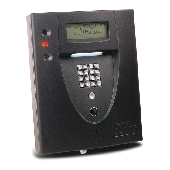
EL 25 Mounting
1
2
Disconnect
2 connectors
Unlock
3
4
Remove and
securely mount
to wall or
Screw
pedestal post
Notch
EL 2000 Mounting
2
1
Unlock
J2
J1
Disconnect J1 and J2
wire harnesses (optional)
3
4
Lift up
Remove
cover
cover
(optional)
(optional)
9
From the Keypad:
Enter Programming Mode
Audio
Feedback
Will Be
Heard
Factory Password
For more information, refer to the Keypad Programming Manual
114A2996C
for the EL Model telephone entry/access control systems
Single Family Home
6
AC Power 12 VAC
polarity doesn't matter
USE 14 AWG
J1
J2
7
12 Gauge Minimum
Set the Clock Sequence
Year
Month
Day
Weekday
24-Hour Time
2005
January
1st
Saturday
1:00PM
1 = Sunday
0200 = 2AM
3 = Tuesday
0800 = 8AM
5 = Thursday
2100 = 9PM
5
Bypass Board
Residence Phone
(Mount in the House)
Alarm System Position
BYPASS
OPERATE
Ring
Tip
4 3 2 1
Ring
Tip
HOME
TELCO
SYSTEM
Ring
Tip
USE 18-24 AWG
2 twisted pair
TIP
EXIT
REQ 4
J7
COM
RING
DOOR
STAT 4
EXIT
RES
REQ 3
J6
POSTAL
3
J3
COM
DOOR
4
STAT 3
EXIT
AUTO
J4
REQ 2
J5
COM
TELCO
DOOR
J1
STAT 2
1
POWER
2
12VAC/DC
EXIT
REQ 2
J4
COM
DOOR
STAT 1
TIP
RING
IMPORTANT: Run ALL wires through conduit hole.
Green Ground Wire
Maximum Distance of 12 ft.
The unit MUST be properly grounded!
Refer to local codes for grounding
recommendations.
© 2006 The Chamberlain Group, Inc.
DO NOT ground the unit to the
pedestal post if one is used.
Relay Time Sequence
Audio
Relay No.
Seconds
Feedback
Will Be
Heard
2 second setting recommended for gate relay.
If you make an error during an entry, press the asterisk key (*) to begin the sequence again.
1 long beep at the end of a sequence is an incorrect sequence, re-enter the correct sequence.
(If applicable)
Telco Entrance Box
Demarcation Point
J5
Follow ALL local
RELAY 4
electrical codes
J4
8
RELAY 3
J3
Normally Open
J1
Common
RELAY 2
Use
18-24 AWG
RELAY 1
Miracle-One™
®
All Rights Reserved
Enter Entry Code Sequence
Audio
From 3 to 9 Digits
Audio
Feedback
Feedback
Will Be
Will Be
Heard
Heard
Choose Entry Code
SL585
SW490
6
5
5 6
SL3000UL™
CSW200UL™
®
9
10
9
Strike Open
10
®
LAKE FOREST, CALIFORNIA
www.eliteaccess.com
REV A
SINGLE OR MASTER ONLY
SECOND ONLY
MOTOR
BRAKE
LIMITS
MOTOR
BRAKE
LIMITS
1
2
3
4
5
6
7
8
9
10
11
12
13
14
15
16
17
18
19
20
21
22
23
24
25
26
27
21 22
Strike Input
21
or
22
(Exit Loop)
Exit Programming Mode
Basic Install
3 Short Beeps
Will be Heard
Complete
When Entry Code is keyed
into the EL Model, the gate
will open
Advertisement


