Chamberlain LiftMaster LA412 Owner's Manual
The chamberlain group, inc. 12 volt dc single solar residential gate operator owner's manual
Hide thumbs
Also See for LiftMaster LA412:
- Owner's manual (44 pages) ,
- Installation manual (52 pages) ,
- Instruction manual (52 pages)
Table of Contents
Advertisement
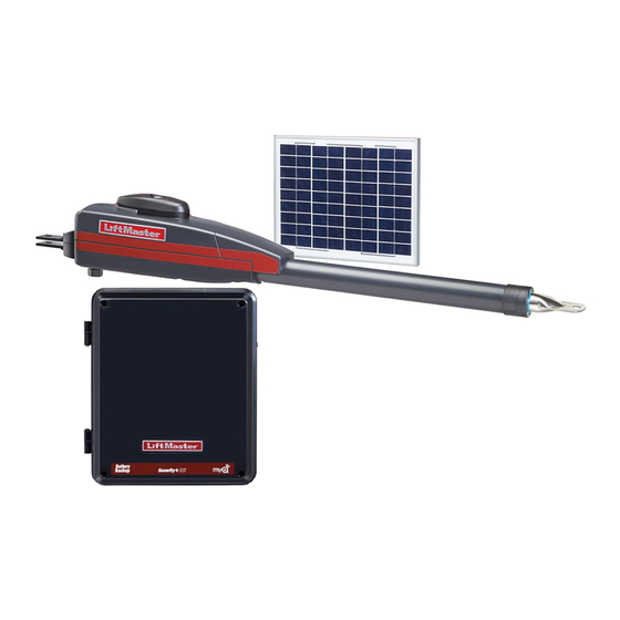
12 VOLT DC SINGLE
SOLAR RESIDENTIAL GATE OPERATOR
Models LA412 and LA412-S
For Residential Use Only
Owner's Manual
Please read this manual and the enclosed safety materials carefully!
■
Periodic checks of the operator by a qualified technician are required to ensure
■
safe operation.
The model number label is located inside the control box of your operator.
■
Serial #
■ ■
Installation Date
■ ■
The Chamberlain Group, Inc.
845 Larch Avenue
Elmhurst, Illinois 60126-1196
www.liftmaster.com
Advertisement
Table of Contents

Related Manuals for Chamberlain LiftMaster LA412


Summary of Contents for Chamberlain LiftMaster LA412
- Page 1 12 VOLT DC SINGLE SOLAR RESIDENTIAL GATE OPERATOR Models LA412 and LA412-S For Residential Use Only Owner’s Manual Please read this manual and the enclosed safety materials carefully! ■ Periodic checks of the operator by a qualified technician are required to ensure ■...
-
Page 2: Table Of Contents
Connect Gate Operator (Gate 1) to Control Box 24-26 Connect Gate Operator (Gate 2) to Control Box (Model LA412-S Only) INTRODUCTION Safety Symbol and Signal Word Review This gate operator has been designed and tested to offer safe service provided it is installed, operated, maintained and tested in strict accordance with the instructions and warnings contained in this manual. - Page 3 Operator Dimensions and Specifications Main Supply Accessory Power Battery Charger Supply (Optional) 14.5Vac nominal, 30 VA max. Maximum Gate Length and Weight 16 ft. at 550 lbs. Temperature Protection Fuse Battery 1 Protection Fuse Battery 2 4.50" (11.2 cm) 12VDC Battery run. Operational between 11.5VDC and 14.5VDC. 12V nominal Class II battery voltage source is limited to: •...
-
Page 4: Safety Installation Information
SAFETY INSTALLATION INFORMATION 1. READ and FOLLOW all instructions. 2. The gate operator is intended for use with Class I vehicular swing gates. Class I denotes a vehicular gate operator (or system) intended for use in a home of one to four single family dwellings, or a garage or parking area associated therewith. - Page 5 13. Each gate operator is provided with two safety warning placards. The placards are to be installed on the front and back of the gate where they are plainly visible. The placards may be mounted using cable ties through the four holes provided on each placard.
-
Page 6: Carton Inventory
2 Batteries Gate Operator Model LA412 (1) Model LA412-S (2) Hardware Inventory NOTE: Hardware quantities shown below are for LA412. Quantities are doubled for LA412-S. Hex Nut 5/16"-18 (1) Flat Washer 5/16" (1) Lock Washer 5/16" (1) Hex Nut 3/8"-16 (3) Hex Bolt 5/16"-18 x 1-1/2 (1) -
Page 7: Additional Items For Purchase
Deep Well Sockets and Wrench 1/2", 5/8", 7/16", 9/16" and 1/4" Carpenter's Level Screwdriver LA412-S ONLY: CONDUIT UL Listed outdoor electrical conduit with 3/4" diameter to hold the extension cable between the junction box and the control box. Drill Bits 1/2", 3/16", 5/16"... -
Page 8: Preparation And Overview
OVERVIEW OF TYPICAL INSTALLATION LEFT-HAND GATE Antenna Control Box Hinge with Batteries Solar Panel (facing South) PVC Conduit (not provided) to protect the power cable for solar and low voltage wire from lawn mowers and string trimmers. gauge wire Earth Ground Installation (Optional) 8 ft. - Page 9 Dual Gate Typical Installation Warning Sign Hinge Solar Panel Antenna (facing South) Post Bracket Gate 1 Operator Cable Control Box with Batteries PVC Conduit (not provided) to protect the power cable for solar and low voltage wire from lawn mowers and string trimmers.
-
Page 10: Check Your Gate
Check Your Gate Gate MUST be level. Remove ANY/ALL wheels from the bottom of gate. Gate MUST NOT hit or drag across ground. Gate MUST swing freely and be supported entirely by its hinges. Preparation and Overview... -
Page 11: Mounting Options
Mounting Options Mounting locations vary depending on the type and style of your gate. NOTES: • The top of the operator must be mounted at least 10 inches above the ground. Environmental conditions should be considered at this time. • The operator is not recommended for plastic or vinyl gates. Contact the gate’s manufacturer for recommendations and options. Recommended: = Gate post bracket mounting locations = Gate bracket mount locations... -
Page 12: Installation
INSTALLATION MANUAL RELEASE Insert the key into the lock and turn it 180° counterclockwise. Turn the release lever 180° counterclockwise. The operator is now in manual mode. DETERMINE THE POSITION OF THE EXTENSION BRACKET The extension bracket can be assembled to work on a Left-Hand or a Right-Hand gate. Review the gate types below and select the type of installation required. - Page 13 MEASURING AND MARKING FOR THE GATE BRACKET Before proceeding, begin with the gate in the fully closed position. There are two methods for determining the proper location of the post brackets: • Paper template (located on the back page of this manual. Must be cut out.) •...
- Page 14 POSITION THE EXTENSION BRACKET TO POST BRACKET Assemble the post bracket by placing the extension bracket on top of post bracket. Insert the bolt through the brackets and fasten them using the washer, lock washer and nut. DO NOT TIGHTEN AT THIS TIME. LEFT-HAND GATE Hex Bolt 3/8"...
- Page 15 POSITION GATE OPERATOR ON GATE The post bracket assembly can be mounted several places on the gate post. Refer to page 11 for mounting options. Place the operator arm against gate post at the desired vertical position and temporarily secure post bracket with a clamp.
- Page 16 TEST GATE TRAVEL Manually open and close the gate. Ensure that the operator does not bind against the pull-to-open bracket. Ensure that the piston does not bottom out. NOTE: If gate does not open and close completely adjust the position of the gate bracket and mark new mounting holes. Installation 1/2"...
- Page 17 SECURE POST BRACKET TO GATE POST Mark holes for the post bracket. Remove the clamp and the operator, and set both aside. Next, drill adequate holes in the gate post. Secure the post bracket to the gate post using hardware. The gate operator (arm) must be level. Flat Washers Hex Nuts Lock Washers...
- Page 18 WARNING SIGN PLACEMENT MUST Warning placards sides of the gate and in plain view. Fasten them to the gate with cable ties. Gate Post Fence If installing a 2nd operator, repeat installation steps 1-11 for the second Installation be installed on both To prevent SERIOUS INJURY or DEATH from a moving gate: •...
-
Page 19: Mount The Control Box
MOUNT THE CONTROL BOX The control box MUST be mounted within 5' of the gate operator. Mount the control box as high as possible for best radio reception. Open the Control Box Remove screws and open the control box. Remove the Control Board Disconnect the reset button, alarm, and coaxial connector. - Page 20 MOUNT THE CONTROL BOX (CONTINUED) Secure the control box to mounting surface (post, wall, column, etc.) using the appropriate hardware (not provided). Square Gate Post Screw (Not Provided) INSTALL THE CONTROL BOARD Attach the antenna. Reinstall the batteries, control board, alarm, and reset button. NOTE: Make sure the battery leads are on the left side of the control box and not pinched.
- Page 21 WIRING To reduce the risk of SEVERE INJURY or DEATH: • BEFORE installing power wiring or control stations be sure to follow ALL specifi cations and warnings described below. • ANY maintenance to the operator or in the area near the operator MUST not be performed until the batteries are disconnected.
- Page 22 CONNECT THE OPERATOR TO THE CONTROL BOARD Extend the operator cable and wires to the Gate 1 connector and connect as shown. Tighten watertight connector nut. GATE 1 ACCESSORY POWER If installing one operator, proceed to page 27. If installing two operators, continue to the next page. Wiring R223 ALARM...
- Page 23 Connect the Gate Operator (Gate 2) to the Control Box (Model LA412-S Only) Occasionally in dual gate installations, one gate will need to open fi rst and close second. This would happen if there was an ornamental overhang on one gate or if using a solenoid lock, for example. This gate is called the Primary gate and C7Ø...
- Page 24 CONNECT SECOND OPERATOR TO CONTROL BOARD (MODEL LA412-S ONLY) • Before digging, contact local underground utility locating companies. • Trench across driveway to bury the extension cable. • Use PVC conduit to prevent damage to cables. • Select hole in bottom of the control box to be used for the extension cable.
- Page 25 JUNCTION BOX The following items are required to complete the junction box installation: • 4 x 4 Junction Box with 3/4" NPT threaded port holes • Screws • PVC Conduit Open the junction box by removing screws (4) and set aside. Mount the junction box within 5' of second operator.
-
Page 26: Wiring
CONNECT WATERTIGHT CONNECTORS Route operator cable and extension cable through watertight connector nut and watertight connector. Insert cables and watertight connectors into the holes in the bottom of the junction box (not provided). Feed extension cable through PVC conduit and secure with connector nut. -
Page 27: Solar Panel Installation
10' cable. If a location near the control box cannot be found, an additional cable will be required. The LA412 Solar Gate Operator is not supported in northern climates where temperatures reach below -4F. This is due to cold weather and a reduced number of hours of sunlight during the winter months. -
Page 28: Overview Of Solar Panel Installation
OVERVIEW OF SOLAR PANEL INSTALLATION Make sure the control box has two 12V 7AH batteries installed. Do not connect batteries until instructed. Solar Panel Installation Solar Panel (facing South) Control Box... -
Page 29: Position Solar Panel(S)
POSITION SOLAR PANEL(S) NOTE: If the panel(s) is not casting a shadow, the battery is not being charged. The location of the panel(s) is critical to the success of the installation. In general, the panel(s) should be mounted using the provided angle bracket facing due south. The solar panel(s) should be mounted in an area clear of all obstructions and shading from buildings and trees. -
Page 30: Position Solar Bracket
POSITION SOLAR BRACKET Position solar bracket on mounting surface. Mark and drill holes. NOTE: Solar panel(s) MUST be installed facing south. Use a compass to determine direction. INSERT MOUNTING BOLTS Insert two bolts into the track located on the back of the solar panel(s). SECURE SOLAR PANEL(S) TO SOLAR BRACKET Secure solar panel(s) to solar bracket using two washered nuts. -
Page 31: Connect Solar Panel(S) To Operator Control Box
CONNECT SOLAR PANEL(S) TO OPERATOR CONTROL BOX Open the control box cover. Disconnect all power and batteries from the control board. Run the solar panel cable to the bottom of the control box. Thread the cable through the watertight connector and pull the cable through until it reaches the AC PWR/SOLAR connector on the control board. -
Page 32: Connect Batteries
CONNECT BATTERIES The batteries are charged in circuit by using the solar panel (provided). Locate the two white battery plugs on the left-hand side of the control box. Connect the plug from the battery to connector on the control board. NOTES: Batteries will degrade over time depending on temperature and usage. -
Page 33: Programming
PROGRAMMING Program Limits The limits are internal settings that indicate when the gates are in the fully open position and the fully closed position. For proper functionality, the limits must be programmed during the installation process. The programming uses a combination of buttons on the control board. - Page 34 NOTES: • The gate with the longer travel span (opening) must be set as the primary gate (GATE 1). • If one gate is overlapping the other, the gate that is overlapping must be connected to GATE 1 so it will start moving before the other gate;...
-
Page 35: Force And Timer To Close
Force and Timer to Close FORCE ADJUSTMENT The operator is equipped a with an obstruction sensing feature. If the gate encounters an obstruction the operator will automatically reverse direction and stop. Based on the length and weight of the gate it may be necessary to make force adjustments. -
Page 36: To Add Or Reprogram A Remote Control
To Add or Reprogram a Remote Control (not provided) 1. Press LEARN XMITTER button and release (LED will light up). 2. Press remote button, the LED will fl ash, alarm output will activate twice. 3. Repeat steps 1 and 2 until all remote controls are programmed (50 remote controls maximum). -
Page 37: Operation And Maintenance
OPERATION AND MAINTENANCE IMPORTANT SAFETY INSTRUCTIONS To reduce the risk of SEVERE INJURY or DEATH: 1. READ AND FOLLOW ALL INSTRUCTIONS. 2. NEVER let children operate or play with gate controls. Keep the remote control away from children. 3. ALWAYS keep people and objects away from the gate. NO ONE SHOULD CROSS THE PATH OF THE MOVING GATE. -
Page 38: Manual Release
MANUAL RELEASE In case of a power failure, the operator can be disengaged from the gate. With an operator, the release action may sometimes feel stiff/jerky, which is normal and has no effect on function. RELEASE 1. Insert the key into the lock. 2. -
Page 39: Wiring Diagram
Wiring Diagram Fault Alarm Automatic Gate Lock (optional) Gate 1 (Primary) Gate 2 (Secondary) To protect against fire and electrocution: • DISCONNECT power and battery BEFORE installing or servicing operator. For continued protection against fire: • Replace ONLY with fuse of same type and rating. To protect against fi... -
Page 40: Diagnostic Chart
Diagnostic Chart Your gate operator is programmed with self-diagnostic capabilities. The diagnostic LED will fl ash a number of times then pause signifying it has found a potential issue. Consult Diagnostic Chart below. Operator is in sleep mode. Normal Operation CONTINUOUS FLASHES (Heartbeat) Power ON... -
Page 41: Troubleshooting
Troubleshooting SYMPTOM Operator does not run. Diagnostic LED not on. Operator powers up but does not run. Relays “click” when remote control or single button control (SBC) command is given, but the operator does not move or arm disconnected. POSSIBLE SOLUTION •... - Page 42 SYMPTOM The arm moves but cannot exit Learn Limits mode. Cannot learn limits. Gate does not fully open or close when trying to learn limits. Unit does not respond to single button control (SBC) command. Unit does not respond to remote control command.
- Page 43 SYMPTOM POSSIBLE SOLUTION Gate opens but does not • An open input is continuously activated. Check the open loop or vehicle probe to close. • Low battery. Measure the voltage across the battery. Voltage should be above • (Optional Accessory) Entry system output is connected to the OPEN input, and is •...
-
Page 44: Repair Parts
K1A6426-1 Control Board with Mounting Bracket K23-19380 Reset Switch K74-34392 Antenna 29-NP712 Battery K76-19446 Alarm SOLPNL10W12V Solar Panel Not Shown LA412-CONT Complete Control Box K1A6636 Receiver Module 315MHz K1A6636-1 Receiver Module - 390MHz (optional) PART # DESCRIPTION 41ASWG-442SA Release Lever... -
Page 45: Accessories
ACCESSORIES 373LM 3-Button SECURITY✚ Control: Includes visor clip. PRESS 50-220 Protector System R ING The Safety Sensors are recommended for installation with the operators covered in this manual. Automatic Gate Lock: SGLOCK12V Solenoid-driven lock that automatically unlocks when gate is open and locks when gate is closed. -
Page 46: Warranty
WARRANTY POLICY The Chamberlain Group, Inc. warrants to the first retail purchaser of this product, for the structure in which this product is originally installed, that it is free from defect in materials and/or workmanship for a period of ONE year from the date of purchase. The proper operation of this product is dependent on your compliance with the instructions regarding installation, operation, maintenance and testing. - Page 48 TEMPLATE FOR POST BRACKET MOUNTING © 2008, The Chamberlain Group, Inc. 01-34491B All Rights Reserved...