Table of Contents
Advertisement
Available languages
Available languages
GARAGE DOOR OPENER
For Residential Use Only
Owner's Manual
■
Please read this manual and the enclosed safety materials carefully!
Fasten the manual near the garage door after installation.
■
■
Periodic checks of the opener are required to ensure safe operation.
■
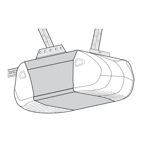
The model number label is located on the front panel of your opener.
®
Model 1210E FS2
The Chamberlain Group, Inc.
845 Larch Avenue
Elmhurst, Illinois 60126-1196
Model 1220E FS2
Advertisement
Chapters
Table of Contents

Related Manuals for Chamberlain Security+ 1210E FS2


Summary of Contents for Chamberlain Security+ 1210E FS2
- Page 1 Periodic checks of the opener are required to ensure safe operation. ■ The model number label is located on the front panel of your opener. ® Model 1210E FS2 The Chamberlain Group, Inc. 845 Larch Avenue Elmhurst, Illinois 60126-1196 Model 1220E FS2...
-
Page 2: Table Of Contents
Safety Symbol and Signal Word Review This garage door opener has been designed and tested to offer safe service provided it is installed, operated, maintained and tested in strict accordance with the instructions and warnings contained in this manual. WARNING... -
Page 3: Preparing Your Garage Door
To prevent damage to garage door and opener: • ALWAYS disable locks before installing and operating the opener. • ONLY operate garage door opener at 120V, 60 Hz to avoid malfunction and damage. Tools needed During assembly, installation and adjustment of the opener, instructions will call for hand tools as illustrated below. -
Page 4: Planning
Planning Identify the type and height of your garage door. Survey your garage area to see if any of the conditions below apply to your installation. Additional materials may be required. You may find it helpful to refer back to this page and the accompanying illustrations as you proceed with the installation of your opener. - Page 5 Planning (Continued) ONE-PIECE DOOR INSTALLATIONS • Generally, a one-piece door does not require reinforcement. If your door is lightweight, refer to the information relating to sectional doors in Installation Step 10. • Depending on your door’s construction, you may need additional mounting hardware for the door bracket (Step 10).
-
Page 6: Planning
Planning (Continued) GATE INSTALLATIONS • It is recommended that you attach fine mesh or screening across the inside of swinging or sliding gates in order to prevent intruders from reaching through the bars and releasing the trolley from the door arm or pressing the door control button. •... -
Page 7: Carton Inventory
Carton Inventory Your garage door opener is packaged in one carton which contains the motor unit and the parts illustrated below. Note that accessories will depend on the model purchased. If anything is missing, carefully check the packing material. Model 1220E Only... -
Page 8: Hardware Inventory
Hardware Inventory Separate all hardware and group as shown below for the assembly and installation procedures. Washered Bolt 5/16"-18x1/2" (2) (mounted in opener) Trolley Threaded Shaft (1) Lag Screw 5/16"-9x1-5/8" (4) Carriage Bolt 5/16"-18x2-1/2" (2) Clevis Pin 5/16"x2-3/4" (1) Assembly Hardware 41A3534 Hex Bolt 5/16"-18x7/8"... -
Page 9: Assembly
Assemble the T-Rail and Attach the Chain Pulley Bracket To avoid installation difficulties, do not run the garage door opener until instructed to do so. 1. Place the 3 T-rail sections on a flat surface for assembly. The end sections are identical. The center... - Page 10 Assemble the T-Rail and Attach the Chain Pulley Bracket To avoid installation difficulties, do not run the garage door opener until instructed to do so. 1. Place the 3 T-rail sections on a flat surface for assembly. The end sections are identical. Make sure the "arrow label"...
-
Page 11: Install The Trolley
ASSEMBLY STEP 2 For Sectional and One-Piece Doors Only Install the Trolley • Attach the trolley threaded shaft to the trolley with the lock washer and nuts as shown. • As a temporary stop, insert a screwdriver into the hole in the front end of the T-rail. •... -
Page 12: Fasten The T-Rail To The Motor Unit
ASSEMBLY STEP 3 Fasten the T-Rail to the Motor Unit • Place the opener on packing material to protect the cover. For convenience, put a support under the chain pulley bracket. • Remove the two 5/16"-18x1/2" washered bolts mounted in the top of the motor unit. •... - Page 13 Back Tab Slot Front Tab Slot Mounting Plate To avoid possible SERIOUS INJURY to fingers from moving garage door opener: • ALWAYS keep hand clear of sprocket while operating opener. • Securely attach sprocket cover BEFORE operating. Leave Chain & Cable...
- Page 14 ASSEMBLY STEP 4 For Sliding and Swinging Gates Only Install the Chain and Attach the Sprocket Cover INSTALLING THE CHAIN 1. Dispense a few inches of chain from carton and fasten to trolley with a master link from the Keep Chain Taut When Dispensing hardware bag.
-
Page 15: Tighten The Chain
4. Disable all locks and remove all ropes connected to garage door before installing opener to avoid entanglement. 5. Install garage door opener 2.1 m or more above floor. 6. Mount emergency release handle 1.8 m above floor. 7. NEVER connect garage door opener to power source until instructed to do so. -
Page 16: Determine The Header Bracket Location
INSTALLATION STEP 1 Determine the Header Bracket Location WARNING To prevent possible SERIOUS INJURY or DEATH: • Header bracket MUST be RIGIDLY fastened to CAUTION structural support on header wall or ceiling, otherwise garage door might not reverse when required. DO NOT install header bracket over drywall. - Page 17 ONE-PIECE DOOR WITHOUT TRACK 1. Close the door and mark the inside vertical centerline of your garage door. Extend the line onto the header wall above door, as shown. If headroom clearance is minimal, you can install the header bracket on the ceiling. See page 18. If you need to install the header bracket on a 38 mm board (on wall or ceiling), use lag screws (not provided) to securely fasten the 38 mm board...
-
Page 18: Install The Header Bracket
INSTALLATION STEP 2 Install the Header Bracket You can attach the header bracket either to the wall above the garage door, or to the ceiling. Follow the instructions which will work best for your particular requirements. Do not install the header bracket over drywall. -
Page 19: Attach The T-Rail To The Header Bracket
INSTALLATION STEP 3 Attach the T-Rail to the Header Bracket • Position the opener on the garage floor below the Header Wall Header Bracket Chain Pulley Bracket • Position the rail bracket against the header • Align the bracket holes and join with a clevis pin •... -
Page 20: Position The Opener
INSTALLATION STEP 4 Position the Opener Follow instructions which apply to your door type as illustrated. SECTIONAL DOOR OR ONE-PIECE DOOR WITH TRACK A 38 mm board is convenient for setting an ideal door-to-T-rail distance. • Raise the opener onto a stepladder. You will need help at this point if the ladder is not tall enough. -
Page 21: Hang The Opener
Hex Bolt 5/16"-18x7/8" Nut 5/16"-18 To avoid possible SERIOUS INJURY from a falling garage door opener, fasten it SECURELY to structural supports of the garage. Concrete anchors MUST be used if installing any brackets into masonry. Figure 1 Bolt 5/16"-18x7/8"... -
Page 22: Install The Door Control
CAUTION INSTALLATION STEP 6 Install the Door Control Locate door control within sight of the door at a minimum height of 1.5 m where small children cannot reach, and away from moving parts of the door and door hardware. The installation surface must be smooth and flat. -
Page 23: Install The Lights
• Reverse the procedure to close the lens. • If the bulbs burn out prematurely due to vibration, replace with a Garage Door Opener bulb. NOTE: Use only standard light bulbs. The use of short neck or speciality light bulbs may overheat the endpanel or light socket. -
Page 24: Electrical Requirements
WARNING INSTALLATION STEP 9 Electrical Requirements CAUTION To avoid installation difficulties, do not run the opener at this time. To reduce the risk of electric shock, your garage door opener has a grounding type plug with a third grounding pin. This plug will only fit into a grounding type outlet. -
Page 25: Fasten The Door Bracket
INSTALLATION STEP 10 Fasten the Door Bracket Follow instructions which apply to your door type as illustrated below or on the following page. A horizontal reinforcement brace should be long enough to be secured to two vertical supports. A vertical reinforcement brace should cover the height of the top panel. - Page 26 ONE-PIECE DOORS Please read and comply with the warnings and reinforcement instructions on the previous page. They apply to one-piece doors also. • Center the door bracket on the top of the door, in line with the header bracket as shown. Mark either the left and right, or the top and bottom holes.
-
Page 27: Connect Door Arm To Trolley
INSTALLATION STEP 11 Connect Door Arm to Trolley Follow instructions which apply to your door type as illustrated below and on the following page. SECTIONAL DOORS ONLY • Make sure garage door is fully closed. Pull the emergency release handle to disconnect the outer trolley from the inner trolley. -
Page 28: Connect The Door Arm To The Trolley
ALL ONE-PIECE DOORS 1. Assemble the door arm: • Fasten the straight and curved door arm sections together to the longest possible length (with a 2 or 3 hole overlap). • With the door closed, connect the straight door arm section to the door bracket with the 5/16"x1-1/4"... -
Page 29: Adjustment
ADJUSTMENT STEP 1 Adjust the UP and DOWN Travel Limits Limit adjustment settings regulate the points at which the door will stop when moving up or down. To operate the opener, press the Door Control push bar. Run the opener through a complete travel cycle. •... -
Page 30: Adjust The Force
ADJUSTMENT STEP 2 Adjust the Force Force adjustment controls are located on the back panel of the motor unit. Force adjustment settings regulate the amount of power required to open and close the door. If the forces are set too light, door travel may be interrupted by nuisance reversals in the down direction and stops in the up direction. -
Page 31: Test The Safety Reversal System
ADJUSTMENT STEP 3 Test the Safety Reversal System Garage Door Installation TEST • With the door fully open, place a 38 mm obstacle on the floor, centered under the garage door. • Operate the door in the down direction. The door must reverse on striking the obstruction. -
Page 32: Operation
• The wall-mounted Door Control: Hold the push button or bar down until the door starts to move. • The Keyless Entry (See Accessories): If provided with your garage door opener, it must be programmed before use. See Programming. When the opener is activated 1. -
Page 33: Using The Wall-Mounted Door Control
Using the Wall-Mounted Door Control THE LIGHTED DOOR CONTROL BUTTON (MODEL 1210E) Press the button to open or close the door. Press again to reverse the door during the closing cycle or to stop the door while it's opening. THE MULTI-FUNCTION DOOR CONTROL (MODEL 1220E) Press the push bar to open or close the door. -
Page 34: Having A Problem
Care of Your Opener LIMIT AND FORCE ADJUSTMENTS Weather conditions may cause some minor changes in door operation requiring some readjustments, particularly during the first year of operation. Pages 29 and 30 refer to the limit and force adjustments. Only a screwdriver is required. -
Page 35: Having A Problem
10. The opener lights don't turn on: • Replace the light bulbs (100 watts maximum). Use a standard neck garage door opener bulb if regular bulb burns out. 11. The opener lights don't turn off: •... -
Page 36: Programming
The owner of the copyright in the garage door opener does not authorize the purchaser or supplier of the non-rolling code transmitter to circumvent that technical measure. -
Page 37: To Add, Reprogram Or Change A Keyless Entry Pin
To Add, Reprogram or Change a Keyless Entry PIN NOTE: Your new Keyless Entry must be programmed to operate your garage door opener. USING THE LIGHTED DOOR CONTROL NOTE: These methods requires two people if the Keyless Entry is already mounted outside the garage. -
Page 38: Motor Unit Assembly Parts
Motor Unit Assembly Parts PART DESCRIPTION 31D380 Sprocket cover (Model 1210E) 41A4208-2 Chain spreader (Model 1220E) 41C4206-2 Gear and sprocket assy. (Model 1220E) 41C4798-2 Gear and sprocket assembly (Model 1210E) Complete with: Spring washer, thrust washer, retaining ring, bearing plate, roll pins (2), drive gear and worm gear, helical gear w/retainer and grease... -
Page 39: Accessories
976-315LM SECURITY✚ ® Keyless Entry: Enables homeowner to operate garage door opener from outside by entering a password on a specially designed keyboard. Also can add a temporary password for visitors or service persons. This temporary password can be limited to a programmable number of hours or entries. -
Page 40: Service Numbers
60 full months (5 years) from the date of purchase. Model Series 1210E FS2: The motor is warranted to be free from any defect in materials and/or workmanship for a period of 48 full months (4 years) from the date of purchase. - Page 41 ■ Se deben realizar revisiones periódicas del abre-puertas para asegurar su operación segura. ■ La etiqueta con el número de modelo de su abre-puertas de garaje está en el panel delantero. Modelo 1210E FS2 The Chamberlain Group, Inc. 845 Larch Avenue Elmhurst, Illinois 60126-1196...
- Page 42 CONTENIDO Introducción Revisión de los símbolos y términos de seguridad...2 Preparación de la puerta de su garaje...3 Herramientas necesarias ...3 Planificación ...4-6 Inventario de las cajas de cartón ...7 Inventario de piezas ...8 Ensamblado Ensamblar el riel en “T” y sujetar la ménsula ...9-10 Instalar el carro...11 Fijar riel “T”...
-
Page 43: Preparación De La Puerta De Su Garaje
Preparación de la puerta del garaje Antes de comenzar: • Desarme las cerraduras. • Retire cualquier cuerda o cable que esté conectado a la puerta. ADVERTENCIA • Haga la siguiente prueba con su puerta para verificar que esté equilibrada y que no se atore ni se atasque: 1. -
Page 44: Planificación
Planificación Identifique la altura y el tipo de puerta de garaje que tiene. Revise el área de su garaje y observe si alguna de las siguientes instalaciones corresponden a la suya. A veces se requieren materiales adicionales, así que tal vez sea conveniente tener esta hoja y las ilustraciones correspondientes a la mano cuando inicie la instalación de su abre-puertas. - Page 45 Planificación (continuación) INSTALACIÓN EN PUERTAS DE UNA SOLA PIEZA • Generalmente una puerta de una sola pieza no requiere de refuerzos adicionales. Si usted tiene una puerta de material liviano y quiere reforzarla, consulte la información respecto a puertas seccionales, contenida en Instalación, Paso 10.
- Page 46 Planificación (continuación) INSTALACIÓN DEL ABRE-PUERTAS • Se recomienda colocar una malla fina a través de la puerta corrediza o batiente, con el objeto de evitar que cualquier intruso alcance el botón de control o el brazo que desengancha el carrito. •...
-
Page 47: Inventario De Las Cajas De Cartón
Inventario de las cajas Su abre-puertas viene empacado en dos cajas de cartón que contienen el motor y las piezas que se muestran en la siguiente ilustración. Tome nota de que los accesorios van a depender del modelo que haya comprado. Si falta alguna pieza, revise con cuidado el material de empaque ya que en ocasiones las piezas se atoran en el hule espuma. -
Page 48: Inventario De Piezas
Inventario de piezas Antes de la instalación, organice todas las piezas en grupos como se muestra en la siguiente ilustración. Perno con arandela 5/16"-18x1/2" (2) (en el cabezal) Perno roscado del carro (1) Tornillo tirafondo 5/16"-9x1-5/8" (4) Perno de coche 5/16"-18x2-1/2"... -
Page 49: Ensamblado
ENSAMBLADO PASO 1 SOLO para puertas seccionales y de una sola pieza Ensamble de riel “T” con soporte de catarina No encienda ni use el abre-puertas hasta que llegue al paso de la instalación correspondiente, de otra manera corre el riesgo de complicar el proceso de instalación. - Page 50 ENSAMBLADO PASO 1 SOLO para puertas corredizas y batientes Ensamble riel "T" con Soporte de Catarina No encienda ni use el abre-puertas hasta que llegue al paso de la instalación correspondiente, de otra manera corre el riesgo de complicar el proceso de instalación. 1.
- Page 51 ENSAMBLADO PASO 2 Solamente para puertas seccionales y de una sola pieza con rieles Instalar el carro sobre el riel en "T" • Unir la espiga roscada con el carro con arandela y tornillo como se muestra. • Como un tope temporal, inserte un destornillador dentro del orificio ubicado en la parte frontal del riel "T".
-
Page 52: Fijar Riel "T" A Abre-Puertas
ENSAMBLADO PASO 3 Fijar riel "T" al abre-puertas de garaje • Colocar el abre-puertas de garaje material de empaque para proteger la cubierta. Por conveniencia, colocar un soporte abajo de la ménsula. ADVERTENCIA • Quitar los dos pernos con arandela 5/16"-18x1/2" montados en la parte superior del motor. - Page 53 ENSAMBLADO PASO 4 Solamente para puertas seccionales y de una sola pieza con rieles Instalar la cadena y conectar la cubierta del portacadena INSTALACIÓN DE LA CADENA 1. Saque unos cuantos centímetros de cadena de la caja de cartón y sujétela al carro mediante el eslabón maestro que se encuentra en Mantenga la cadena...
- Page 54 ENSAMBLADO PASO 4 Solamente puertas corredizas y batientes Instalar la cadena y conecte la cubierta del portacadena INSTALACIÓN DE LA CADENA 1.Saque unos cuantos centimetros de cadena de la caja de cartón y sujétela al carro mediante el eslabón maestro que se encuentra en la bolsa con la tornillería.
-
Page 55: Apretar La Cadena
ENSAMBLADO PASO 5 Apretar la cadena • Girar la tuerca y la arandela de cierre en la dirección del perno roscado y alejado del carro. • Para aligerar la cadena, girar la tuerca externa en la dirección mostrada. A LA MEDIDA QUE GIRE LA TUERCA, MANTENGA LA CADENA DERECHA. -
Page 56: Determinar La Localización De Soporte De Cabecera
INSTALACIÓN PASO 1 Determinar la localización de soporte de cabecera ADVERTENCIA ADVERTENCIA Para evitar una posible LESIÓN GRAVE O INCLUSO LA MUERTE: • La ménsula del cabezal DEBE quedar RÍGIDAMENTE sujeta al soporte estructural en la pared delantera o en el cielo raso, de no ser así... -
Page 57: La Ménsula Del Cabezal
PUERTA DE UNA SOLA PIEZA SIN RIEL 1. Con la puerta cerrada, buscar y marcar el centro vertical de la puerta del garaje. Extender la línea del centro hasta la pared de cabecera arriba de la puerta, como se muestra en la ilustración. Si el espacio libre para el cabezal es mínimo, se puede instalar el soporte del cabezal en el cielo raso (Ver página 18). -
Page 58: Instale La Ménsula Del Cabezal
INSTALACIÓN PASO 2 Instale la ménsula del cabezal La ménsula del cabezal se puede sujetar a la pared sobre la puerta del garaje o en el cielo raso. Siga las instrucciones que sean las más adecuadas para las necesidades de su garaje. No instale la ménsula del cabezal en un muro falso. -
Page 59: Coloque El Riel En La Ménsula Del Cabezal
INSTALACIÓN PASO 3 Coloque el riel en la ménsula del cabezal • Coloque el abre-puertas sobre el piso del garaje debajo Pared de cabecera de la ménsula del cabezal. Use el hule espuma del empaque como base para protegerlo. NOTA: Si el resorte de la puerta está obstruido, va a Soporte de cabecera necesitar ayuda. -
Page 60: Coloque El Abre-Puertas
INSTALACIÓN PASO 4 Coloque el abre-puertas Siga las instrucciones correspondientes al tipo de puerta de su garaje, como se muestra en la ilustración. PUERTA SECCIONAL O PUERTA DE UNA SOLA ADVERTENCIA PIEZA CON RIEL Un pedazo de madera de 38 mm le será de ayuda al determinar la distancia ideal entre la puerta y el riel. -
Page 61: Cuelgue El Abre-Puertas
INSTALACIÓN PASO 5 Cuelgue el abre-puertas Se muestran dos instalaciónes representativas. Quizá su instalación sea diferente. Las soportes colgantes se deben colocar en ángulo (Figura 1) para lograr un soporte rígido. En los techos acabados (Figura 2), colocar un soporte metá... -
Page 62: Instalar El Control De La Puerta
INSTALACIÓN PASO 6 Instalar el control de la puerta Ubique el control de la puerta de manera que quede a la vista desde la puerta y a una altura mínima de 1.5 m donde los niños pequeños no lo puedan alcanzar y lejos de las partes móviles de la puerta y de la pernería. -
Page 63: Instale El Foco
INSTALACIÓN PASO 7 Instale el foco • Oprima las lengüetas de desenganche ubicados a ambos lados de la lente. Rote la lente suavemente hacia atrás y hacia abajo hasta que la bisagra quede en la posición totalmente abierta. No quite la lente. •... -
Page 64: Requisitos Para La Instalación Eléctrica
ADVERTENCIA INSTALACIÓN PASO 9 Requisitos para la instalación eléctrica Para evitar problemas con la instalación, no opere el abre-puertas de garaje ahora. Para reducir el riesgo de choque eléctrico, su abre-puertas de garaje viene con una clavija de conexión a tierra de tres patas. -
Page 65: Sujete La Ménsula De La Puerta
INSTALACIÓN PASO 10 Sujete la ménsula de la puerta Siga las instrucciones que correspondan al tipo de puerta de garaje que usted tenga, como se muestra en la ilustración o en la página siguiente. ADVERTENCIA Si usa un puntal horizontal, éste debe de ser lo suficientemente largo para sujetarlo a dos soportes verticales. -
Page 66: Puertas De Una Sola Pieza
PUERTAS DE UNA SOLA PIEZA Lea y respete todas las advertencias e instrucciones respecto a los refuerzos, contenidas en la página anterior, respecto a la instalación de puertas plegables, ya que todos los refuerzos para su puerta de una sola pieza son los mismos. -
Page 67: Conectar El Brazo De La Puerta Al Carro
INSTALACIÓN PASO 11 Conectar el brazo de la puerta al carro Siga las instrucciones que correspondan al tipo de puerta de garaje que usted tenga, como se muestra a continuación y en las dos páginas siguientes. SÓLO PARA PUERTA SECCIONAL •... -
Page 68: Conecte El Brazo De La Puerta Al Carro
TODAS LAS PUERTAS DE UNA SOLA PIEZA 1. Arme el brazo de la puerta: • Sujete las dos secciones de los brazos de la puerta (recta y curva) a la mayor distancia posible, (de manera que dos o tres de los orificios se sobrepongan uno al otro). -
Page 69: Ajustes
AJUSTES, PASO 1 Ajuste el límite del recorrido hacia arriba y hacia abajo Al ajustar el límite del recorrido de la puerta, se regula hasta que punto la puerta se detendrá al abrirse y cerrarse. ADVERTENCIA Para activar el abre-puertas de garaje, oprimir el botón iluminado. -
Page 70: Ajuste La Fuerza
AJUSTES, PASO 2 Ajuste la fuerza Los tornillos para el ajuste de la fuerza del abre-puertas se encuentran en el panel posterior del abre-puertas. Estos ajustes controlarán la fuerza que será necesaria para abrir y cerrar la puerta. Si la fuerza está muy débil, es posible que la trayectoría de la puerta esté... -
Page 71: Pruebe El Sistema De Reversa De Seguridad
AJUSTES, PASO 3 Pruebe el sistema de reversa de seguridad Instalación del abre-puertas de garaje PRUEBA • Abra completamente la puerta, coloque un pedazo de madera de 38 mm acostado sobre el piso al centro de la puerta del garaje. •... -
Page 72: Operación
OPERACIÓN INSTRUCCIONES DE SEGURIDAD IMPORTANTES Para reducir el riesgo de LESIONES GRAVES o LA MUERTE: 1. LEA Y RESPETE TODAS LAS ADVERTENCIAS Y LAS INSTRUCCIONES DE OPERACIÓN. 2. SIEMPRE conserve los controles remotos lejos del alcance de los niños. NUNCA permita que los niños operen o jueguen con los botones del control del abre-puertas de garaje ni con los controles remotos. -
Page 73: Cómo Usar La Unidad De Control De Pared
Cómo usar la unidad de control de pared BOTÓN ILUMIINADO DE CONTROL DE LA PUERTA (MODELO 1210E) Presione el botón para abrir o cerrar la puerta. Vuelva a presionarlo para hacer funcionar el mecanismo de reversa de la puerta durante el ciclo de cerrado o para detener la puerta mientras se está... -
Page 74: Mantenimiento De Su Abre-Puertas De Garaje
Mantenimiento de su abre-puertas de garaje AJUSTES DE LÍMITE Y FUERZA Las condiciones climatológicas pueden ocasionar cambios menores en el funcionamiento de la puerta, que requerirá algunos reajustes, en particular durante el primer año de operación. En las páginas 29 y 30 se encuentra la información sobre los ajustes de límite y de fuerza. - Page 75 Si tiene algún problema (continuación) 6. La puerta del garaje se abre y se cierra por sí misma: • Asegúrese que todos los botones del control remoto estén apagados. • Quite el alambre del timbre de las terminales del control de la puerta y haga funcionar la puerta solamente con el control remoto.
-
Page 76: Programación
PROGRAMACIÓN AVISO: Si utiliza este abre puertas de garaje Security ✚ (código aleatorio), se verán circunvenidas las medidas técnicas incorporadas en el receptor del abridor para proteger contra los aparatos de captura de códigos. El propietario de los derechos propiedad intelectual del abridor no autoriza ni al comprador ni al proveedor de un transmisor no dotado de un sistema de códigos de salto (código aleatorio) a circunvenir dichas medidas técnicas. - Page 77 Cómo Agregar, Reprogramar o Modificar el PIN de la Llave Digital NOTA: Su nueva llave digital debe programarse para que accione el abre-puertas de garaje. USO DEL CONTROL DE PUERTA ILUMINADA NOTA: Estos métodos requiere dos personas si la Llave Digital ya está...
-
Page 78: Piezas De La Unidad Del Motor
Piezas de la unidad del motor CLAVE PARTE DESCRIPCIÓN 31D380 Cubierta del portacadena (Modelo 1210E) 41A4208-2 Extendedor de la cadena (Model 1220E) 41C4206-2 Conjunto de engranaje y portacadena (Modelo 1220E) 41C4798-2 Conjunto de engranaje y portacadena (Modelo 1210E) Incluye: Arandela de expansión, arandela de empuje, anillo de retén, placa y chumacera, pernos de expansión (2), engranaje... -
Page 79: Accesorios
ACCESORI0S 970-315LG Minicontrol remoto de 3 botones SECURITY✚ ® Con anillo llavero y tira sujetadora. 971-315LM Control remoto de un botón SECURITY✚ ® Incluye broche del visor. 973-315MK Control remoto de 3 botones SECURITY✚ ® Incluye broche del visor. 98LM Panel de control con la capacidad de detectar movimiento: La unidad de control de funciones... -
Page 80: Garantía
(5 años) a partir de la fecha de compra. Serie modelo 1210E FS2: se garantiza que el motor está libre de cualquier defecto de mantenimiento y mano de obra por un período de 48 meses completos (4 años) a partir de la fecha de compra.