Table of Contents
Advertisement
Available languages
Available languages
MIXER
MELANGEUR
MISCHPULTE
MEZCLA
Operation Manual
Manuel d'instructions
Bedienungsanleitung
Manual de Operación
1
–14
GAIN
+10
–15
HIGH
–15
MID
–15
LOW
0
AUX 1
0
AUX 2
L
PAN
1
MIC IN
2
3
4
5
LINE IN
1
2
3
4
–60
–14
–60
–14
–60
–14
–60
–14
–60
GAIN
GAIN
GAIN
GAIN
–36
+10
–36
+10
–36
+10
–36
+10
–36
+15
–15
+15
–15
+15
–15
+15
–15
+15
HIGH
HIGH
HIGH
HIGH
+15
–15
+15
–15
+15
–15
+15
–15
+15
MID
MID
MID
MID
+15
–15
+15
–15
+15
–15
+15
–15
+15
LOW
LOW
LOW
LOW
10
0
10
0
10
0
10
0
10
AUX 1
AUX 1
AUX 1
AUX 1
10
0
10
0
10
0
10
0
10
AUX 2
AUX 2
AUX 2
AUX 2
R
L
R
L
R
L
R
L
PAN
PAN
PAN
PAN
PEAK
PEAK
PEAK
PEAK
PEAK
PFL
PFL
PFL
PFL
PFL
2
3
4
5
10
10
10
10
5
5
5
5
0
0
0
0
5
5
5
5
10
10
10
10
15
15
15
15
20
20
20
20
30
30
30
30
00
00
00
00
LINE IN
6
7L
9L
11L
MONO
MONO
MONO
5
6
8R
10R
12R
+4dB
–20dB
+4dB
–20dB
+4dB
–20dB
–10dB
–10dB
–10dB
–14
–60
GAIN
+10
–36
–15
+15
–15
+15
–15
+15
–15
+15
HIGH
HIGH
HIGH
HIGH
–15
+15
MID
–15
+15
–15
+15
–15
+15
–15
+15
LOW
LOW
LOW
LOW
0
10
0
10
0
10
0
10
AUX 1
AUX 1
AUX 1
AUX 1
0
10
AUX 2
R
L
R
L
R
L
R
L
R
PAN
BALANCE
BALANCE
BALANCE
PEAK
PEAK
PEAK
PEAK
PFL
PFL
PFL
PFL
6
7
9
11
8
10
12
10
10
10
10
10
5
5
5
5
5
0
0
0
0
0
5
5
5
5
5
10
10
10
10
10
15
15
15
15
15
20
20
20
20
20
30
30
30
30
30
00
00
00
00
00
SUB IN +4dB
TAPE IN –10dBV REC OUT –10dBV
ST OUT +4dB
L
L
L
R
R
R
AUX RETURN –10dB
AUX SEND +4dB MONI OUT +4dB
13L
1L
2L
1
MONO
MONO
MONO
14R
1R
2R
2
+4dB
–20dB
–10dB
L
PHANTOM
–15
+15
00 –20 –15 –10 –6 –3
0
+2 +4 +6
HIGH
R
STEREO GRAPHIC EQUALIZER
+12
+12
9
9
6
6
3
3
0
0
3
3
6
6
–15
+15
9
9
LOW
–12
–12
100
400
1k
5k
10k
MIXER
0
10
AUX 1
0
10
0
10
AUX SEND 1
AUX SEND 2
0
10
0
10
L
R
0
10
BALANCE
AUX RETURN 1
AUX RETURN 2
TAPE IN
PEAK
TO
PFL
MONI
STEREO
13
L
R
14
0
10
10
10
MONITOR
5
5
0
0
5
5
0
10
10
10
PHONES
15
15
20
20
30
30
00
00
L
R
L
R
PFL
Advertisement
Chapters
Table of Contents

Related Manuals for Yamaha MM 1402


Summary of Contents for Yamaha MM 1402
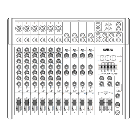
- Page 1 MIXER MELANGEUR MISCHPULTE MEZCLA Operation Manual Manuel d’instructions Bedienungsanleitung Manual de Operación –14 –60 –14 –60 GAIN GAIN –36 –36 –15 –15 HIGH HIGH –15 –15 –15 –15 AUX 1 AUX 1 AUX 2 AUX 2 PEAK PEAK LINE IN MIC IN LINE IN MONO...
- Page 2 If these corrective measures do not produce satisfactory results, please contact the local retailer authorized to distribute this type of product. If you can not locate the appropriate retailer, please contact Yamaha Corporation of America. Electronic Service Division, 6600 Orangethorpe Ave, Buena Park, CA 90620 This applies only to products distributed by YAMAHA CORPORATION OF AMERICA Dette apparat overholder det gaeldende EF-direktiv vedtrørende...
- Page 3 MIXER OPERATION MANUAL...
- Page 4 L or coloured RED. Making sure that neither core is connected to the earth terminal of the three pin plug. This applies only to products distributed by YAMAHA KEMBLE MUSIC (U.K.) LTD. IMPORTANT NOTICE FOR...
-
Page 5: Table Of Contents
Introduction Thank you for purchasing the Yamaha MM1402 mixer. The MM1402 is a mixer that provides 6 MONO IN channels and 4 STEREO IN channels, for a total of 14 inputs. It is a console-type stereo mixer suitable for a wide variety of input sources. -
Page 6: Precautions
4. Do Not Open the Case or Attempt Repairs or Modifi- cations Yourself This product contains no user-serviceable parts. Refer all maintenance to qualified Yamaha service personnel. Opening the case and/or tampering with the internal circuitry voids the warranty. 5. Always power off before making connections Always turn the power OFF before connecting or discon- necting cables. -
Page 7: Control Panel
Control panel Channel control section (mono input section) –14 –60 GAIN –36 –15 HIGH –15 –15 AUX 1 AUX 2 PEAK 1 GAIN control Use this knob to adjust the level of the input signal to the optimal level. For the best balance of S/N ratio and dynamic range, adjust this knob so that the peak indicator 5 lights occasionally. -
Page 8: (Stereo Input Section)
(Stereo input section) +4dB –20dB –10dB –15 HIGH –15 AUX 1 BALANCE PEAK 8 GAIN select switch Use this switch to adjust the sensitivity of the input as appropriate for the level of the input signal. For the best balance of S/N ratio and dynamic range, adjust this switch so that the peak indicator B lights occasionally. -
Page 9: Master Control Section
Master control section 00 –20 –15 –10 –6 –3 +2 +4 +6 STEREO GRAPHIC EQUALIZER –12 MIXER AUX SEND 1 AUX SEND 2 AUX RETURN 1 AUX RETURN 2 STEREO E ST L, R master control These faders adjust the final level of all channels, and output the combined signal to the ST OUT jacks. -
Page 10: Phone Jack
P PHONE jack A set of stereo headphones can be connected to this jack. Normally, the headphones will monitor the same signal as the STEREO OUT jacks, but the following two signals can also be monitored. 1. When a 8 PFL switch is turned on, the signal of the input channel after the equalizer will be monitored. -
Page 11: Panel
Panel MIC IN LINE IN 1 MIC IN These are XLR type connectors to which microphones can be connected (1: GND, 2: hot, 3: cold). The nominal im- pedance is 50–600 . Turn the PHANTOM switch ON to apply +48V DC to Pin 2 and 3 of MIC IN connectors 1–6. -
Page 12: Application Example
Application Example Stage Monitors Power Amp Graphic EQ Effects Processor AUX SEND1 AUX SEND2 MIC IN Mics Front of House Main Speakers Power Amp AUX RETURN L/R MIXER LINE IN LINE IN Line Level Sources Guitar Effect Processor STEREO OUT Cassette Recorder REC OUT L/R CD Player... -
Page 13: Specifications
Specifications General Specifications Maximum output level Total harmonic distortion Frequency response Hum and noise (Average, Rs=150 ) (20Hz–20kHz) Maximum voltage gain Crosstalk Gain control (1–6) INPUT (7L–14R) Input Level Selector INPUT (1–6) Channel equalization INPUT (7L–14R) Channel equalization ST OUT Graphic EQ LED meters Channel PEAK indicators Phantom power... -
Page 14: Input Specifications
Input Specifications Gain Input Input Trim impedance 2.5k MIC IN (1–6) LINE IN (1–6) –20 INPUT –10 (7L–14R) AUX RETURN — (1L–2R) SUB IN — (L/R) TAPE IN — (L/R) 0dB=0.775Vrms., 0dBV=1Vrms Output Specifications Output Output impedance ST OUT (L/R) AUX SEND (1–2) MONITOR OUT (L/R) REC OUT (L/R) -
Page 15: Block And Level Diagrams
Block and Level Diagrams PHANTOM (MIC IN) PHANTOM (PHANTOM) MIC IN 1–6 GAIN LINE IN 1–6 L / MONO +4dB –10dB –20dB LINE IN 7–14 TAPE IN –10dBV L/MONO AUX RETURN –10dB SUB IN +4dB [dB] LINE IN 1–6[+10] LINE IN 7–14[+4] LINE IN 7–14[–10] –10 MIC IN[–14]... - Page 16 MELANGEUR MANUEL D’INSTRUCTIONS...
- Page 17 Introduction Nous vous remercions d’avoir porté votre choix sur le mélangeur MM1402 de Yamaha. Le MM1402 vous propose 6 canaux MONO IN et 4 canaux STEREO IN, un total de 14 bornes donc. Il s’agit d’un mélangeur stéréo de type console adapté pour une large variété de sources d’entrée.
-
Page 18: Précautions
Cet appareil ne contient pas d’élément pouvant être réparé par l’utilisateur. Veuillez donc confier toute réparation à un technicien Yamaha qualifié. Toute tentative d’ouver- ture du boîtier et de manipulation des circuits internes se soldera par la perte du bénéfice de la garantie. -
Page 19: Panneau De Commandes
Panneau de commandes Section du contrôle de canal (section d’entrée mono) –14 –60 GAIN –36 –15 HIGH –15 –15 AUX 1 AUX 2 PEAK 1 Commande GAIN Utilisez ce bouton pour régler le niveau du signal d’entrée de manière opti- male. -
Page 20: (Section D'entrée Stéréo)
(Section d’entrée stéréo) +4dB –20dB –10dB –15 HIGH –15 AUX 1 BALANCE PEAK 8 Sélecteur GAIN Utilisez ce commutateur pour régler la sensibilité de l’entrée en fonction du niveau d’entrée du signal. Pour obtenir le meilleur équilibre entre le rapport signal/bruit et la plage dyna- mique, réglez ce commutateur de telle sorte que la diode de crête B s’allume sporadiquement. -
Page 21: Section Master
Section Master 00 –20 –15 –10 –6 –3 +2 +4 +6 STEREO GRAPHIC EQUALIZER –12 MIXER AUX SEND 1 AUX SEND 2 AUX RETURN 1 AUX RETURN 2 STEREO E Commande master ST L, R Ces curseurs permettent de régler le niveau définitif de tous les canaux et alimentent les bornes ST OUT avec le signal combiné. - Page 22 P Prise PHONE Vous pouvez brancher un casque à cette borne. Normale- ment, le casque contrôle le même signal que les bornes STEREO OUT mais vous pouvez en sus contrôler les si- gnaux suivants: 1. Lorsqu’un commutateur PFL est sur ON, le signal du canal d’entrée après EQ sera contrôlé.
-
Page 23: Panneau
Panneau MIC IN LINE IN 1 MIC IN Connecteurs de type XLR auxquels des microphones peu- vent être branchés (1: Masse, 2: chaud, 3: froid). L’impédance nominale est de 50–600 . Activez le commutateur PHANTOM pour envoyer 48V aux broches 2 et 3 des ces connecteurs (MIC IN 1-6). 2 LINE IN (1–6) Prises casque symétriques auxquelles du matériel de ni- veau ligne peut être branché... -
Page 24: Exemple D'application
Exemple d’application Retours de scène Amplificateur Eqaliseur graphique Processeur d’effets AUX SEND1 AUX SEND2 MIC IN Micros Processeur d’effet pour guitare Haut-parleurs de salle Amplificateur AUX RETURN L/R MIXER LINE IN LINE IN Sources de niveau ligne STEREO OUT Platine à cassette REC OUT L/R Lecteur CD TAPE IN L/R... -
Page 25: Caractéristiques
Caractéristiques Caractéristiques générales Niveau de sortie maximum Distorsion harmonique totale Réponse en fréquence Ronflement et bruit (Moyenne, Rs=150 ) (20Hz–20kHz) Gain de tension moyen Diaphonie Contrôle de gain (1–6) Sélecteur de niveau d’entrée (7L–14R) +4/–10/–20dB* INPUT (1–6) Egalisation de canal INPUT (7L–14R) Egalisation de canal EQ graphique ST OUT... -
Page 26: Caractéristiques D'entrée
Caractéristiques d’entrée Gain Impédance Entrée Trim d’entrée 2.5k MIC IN (1–6) LINE IN (1–6) –20 INPUT –10 (7L–14R) AUX RETURN — (1L–2R) SUB IN — (L/R) TAPE IN — (L/R) 0dB=0.775Vrms., 0dBV=1Vrms Caractéristiques de sortie Impédance Sortie de sortie ST OUT (L/R) AUX SEND (1–2) MONITOR OUT (L/R) REC OUT (L/R) -
Page 27: Schémas De Connexions Et De Niveaux
Schémas de connexions et de niveaux PHANTOM (MIC IN) PHANTOM (PHANTOM) MIC IN 1–6 GAIN LINE IN 1–6 L / MONO +4dB –10dB –20dB LINE IN 7–14 TAPE IN –10dBV L/MONO AUX RETURN –10dB SUB IN +4dB [dB] LINE IN 1–6[+10] LINE IN 7–14[+4] LINE IN 7–14[–10] –10... - Page 28 (Gerät, Typ, Bezeichnung) in Übereinstimmung mit den Bestimmungen der 82/499/EWG (EG-Richtlinie) funkentstört ist. Der Deutschen Bundespost wurde das Inverkehrbringen dieses Gerätes angezeigt und die Berechtigung zur Überprüfung der Serie auf Einhaltung der Bestimmungen eingeräumt. YAMAHA Europa GmbH Name des Importeurs...
- Page 29 Einleitung Vielen Dank, daß Sie sich für ein MM1402 Mischpult von Yamaha entschieden haben. Das MM1402 bietet 6 MONO-Eingangskanäle und 4 STEREO-Eingangskanäle, insgesamt also 14 Eingänge. Es handelt sich um ein Stereo-Konsolengerät, das man für eine Vielzahl von Anwendungsbereichen einsetzen kann.
-
Page 30: Vorsichtsmaßnahmen
MM1402 selbst zu reparieren Dieses Pult enthält keinerlei Teile, die vom Anwender selbst gewartet werden dürfen. Überlassen Sie alle Wartungsarbeiten dem qualifizierten Yamaha-Kunden- dienst. Bitte bedenken Sie, daß beim Öffnen des Gehäuses automatisch der Garantieanspruch erlischt. -
Page 31: Bedienfeld
Bedienfeld Kanalbelegung (Mono-Eingangssektion) –14 –60 GAIN –36 –15 HIGH –15 –15 AUX 1 AUX 2 PEAK 1 GAIN Regler Mit diesem Regler können Sie den Eingangspegel des angelegten Signals optimalisieren. Den besten Fremdspannungsabstand erzielt man bekanntlich, wenn der Ein- gangspegel so eingestellt wird, daß die PEAK Diode 5 nur bei Signalspitzen leuchtet. -
Page 32: (Stereo-Eingangssektion)
(Stereo-Eingangssektion) +4dB –20dB –10dB –15 HIGH –15 AUX 1 BALANCE PEAK 8 GAIN Wahltaster Mit diesem Taster können Sie die Empfindlichkeit des Eingangs an den Pegel des angelegten Signals angleichen. Den besten Fremdspannungsabstand und Dynamikbereich erzielt man, indem man den Eingangspegel so einstellt, daß die PEAK Diode B nur bei Signal- spitzen kurz aufblinkt. -
Page 33: Master-Sektion
Master-Sektion 00 –20 –15 –10 –6 –3 +2 +4 +6 STEREO GRAPHIC EQUALIZER –12 MIXER AUX SEND 1 AUX SEND 2 AUX RETURN 1 AUX RETURN 2 STEREO E ST L, R Master-Fader Mit diesen Fadern bestimmen Sie den Gesamtpegel aller Signale, deren Summe an die ST OUT Buchsen angelegt wird. - Page 34 P PHONES Buchse Mit dieser Buchse können Sie einen Stereo-Kopfhörer verbinden. Normalerweise hören Sie im Kopfhörer das- selbe Signal, wie das an die ST OUT Buchsen angelegte. Folgende Signale kann man jedoch ebenfalls mit einem Kopfhörer überwachen. 1. Wenn Sie einen PFL Taster 8 aktiviert haben, wird das betreffende, hinter dem Equalizer abgegriffene Si- gnal an den Kopfhörer angelegt.
-
Page 35: Anschlußfeld
Anschlußfeld MIC IN LINE IN 1 MIC IN Mit diesen XLR Buchsen können Sie Mikrofone verbin- den (1: Masse, 2: heiß, 3: kalt). Die Nennimpedanz dieser Buchse beträgt 50~600 . Wenn Sie die PHANTOM-Speisung einschalten, wird eine Spannung von +48V an Stift 2 und 3 dieser Buchsen angelegt (MIC IN 1–6). -
Page 36: Anwendungsbeispiel
Anwendungsbeispiel Bühnenmonitore Endstufe Graphischer Equalizer Außenbordeffektgerät AUX SEND1 AUX SEND2 MIC IN Mikrofone Saalbeschallung Endstufe AUX RETURN L/R MIXER LINE IN LINE IN Signaquellen mit Line-Pegel Gitarreneffectprozessor STEREO OUT Cassettendeck REC OUT L/R CD-Spieler TAPE IN L/R Kopfhöver HEAD PHONES... -
Page 37: Spezifikationen
Spezifikationen Allgemeine Spezifikationen Maximaler Ausgangspege Klirrfaktor Frequenzgang Störspannungen (Durchschnitt, Rs= 150 ) (20Hz–20kHz) Maximale Spannungsanhebung Kanaltrennung GAIN-Regler (1–6) Eingangspegel-Wahltaster (7L–14R) +4/–10/–20dB* INPUT (1–6) Kanalentzerrung INPUT (7L–14R) Kanalentzerrung ST OUT grafischer EQ LED-Mete PEAK-Dioden der Kanäle Phantomspeisung Stromanforderungen Leistungsaufnahme Abmessungen (W Gewicht * 0dB=0.775Vrms. -
Page 38: Eingangsspezifikationen
Eingangsspezifikationen Anhebung Eingangs- Eingang Absenkung impedanz 2.5k MIC IN (1–6) LINE IN (1–6) –20 INPUT –10 (7L–14R) AUX RETURN — (1L–2R) SUB IN — (L/R) TAPE IN — (L/R) 0dB=0.775Vrms., 0dBV=1Vrms Ausgangsspezifikationen Ausgangs- Ausgang impedanz ST OUT (L/R) AUX SEND (1–2) MONITOR OUT (L/R) REC OUT (L/R) HEAD PHONE... -
Page 39: Block- Und Pegelregelungsschaltbild
Block- und Pegelregelungsschaltbild PHANTOM (MIC IN) PHANTOM (PHANTOM) MIC IN 1–6 GAIN LINE IN 1–6 L / MONO +4dB –10dB –20dB LINE IN 7–14 TAPE IN –10dBV L/MONO AUX RETURN –10dB SUB IN +4dB [dB] LINE IN 1–6[+10] LINE IN 7–14[+4] LINE IN 7–14[–10] –10 MIC IN[–14]... - Page 40 MEZCLA MANUAL DE OPERACIÓN...
- Page 41 Introducción Gracias por su compra de la consola de mezclas MM1402 de Yamaha. La MM1402 es una consola de mezclas que proporciona 6 canales de Entrada Monoaural (MONO IN) y 4 canales de Entrada Estereofónica (STEREO IN), para un total de 14 entradas. Es una mezcladora estereofónica tipo consola adecuada para una amplia variedad de fuentes de...
-
Page 42: Precauciones
Cuando necesite labores de reparación o mantenimiento avise a personal cualificado de Yamaha. Si abre la cubierta y/o intenta forzar los circuitos internos la garantía quedará anulada. 5. Apague siempre el aparato antes de hacer las conexiones Apague siempre el aparato (OFF) antes de ponerse a conectar o desconectar los cables. -
Page 43: Panel De Control
Panel de Control Sección de control de canal (sección de entrada monoaural) –14 –60 GAIN –36 –15 HIGH –15 –15 AUX 1 AUX 2 PEAK 1 Control de Ganancia (GAIN) Utilice este mando para ajustar el nivel de la señal de entrada hasta alcanzar el nivel óptimo. -
Page 44: (Sección De Entrada Estereofónica)
(Sección de entrada estereofónica) +4dB –20dB –10dB –15 HIGH –15 AUX 1 BALANCE PEAK 8 Interruptor selector de Ganancia (GAIN) Utilice este interruptor para ajustar la sensibilidad de la entrada de forma apropiada para el nivel de la señal de entrada. Para alcanzar el mejor balance de la relación señal/ruido y de la gama dinámica, ajuste este interruptor de forma que el indicador de máximo B se ilumine de vez en cuando. -
Page 45: Sección De Control Principal
Sección de Control Principal 00 –20 –15 –10 –6 –3 +2 +4 +6 STEREO GRAPHIC EQUALIZER –12 MIXER AUX SEND 1 AUX SEND 2 AUX RETURN 1 AUX RETURN 2 STEREO E Control principal Estereofónico Izquierdo/Derecho (ST L, R) Estos atenuadores ajustan el nivel final de todos los canales, y dejan salir la señal combinada hacia las tomas de Salida Estereofónica (ST OUT). - Page 46 N Control de Monitorización (MONITOR) Este mando ajusta el nivel de salida de las tomas de Salida Monitorizada (MONI OUT). O Control Auriculares (PHONES) Este mando ajusta el volumen de los auriculares conectados a las tomas de auriculares. P Toma de Auriculares (PHONE) A esta toma se puede conectar un juego de auriculares estereofónicos.
-
Page 47: Panel
Panel MIC IN LINE IN 1 Entrada de Micrófono (MIC IN) Se trata de conectores tipo XLR a los cuales se pueden conectar micrófonos (1: GND (tierra), 2: caliente, 3: frío). La impedancia nominal es de 50–600 . Conecte el interruptor de PHANTOM para aplicar +48V CC a los pines 2 y 3 de estos conectores. -
Page 48: Ejemplo Aplicable
Ejemplo aplicable Monitores de escenario Amplificador de potencia Ecualizador gráfico Procesador de efectos AUX SEND1 AUX SEND2 MIC IN Micrófono Procesador de efectos de guitarra Altavoces principales frente al edificio Amplificador de potencia AUX RETURN L/R MIXER LINE IN LINE IN Equipos de línea-nivel STEREO OUT Deck de cassettes... -
Page 49: Especificaciones
Especificaciones Especificaciones Generales Nivel máximo de salida Distorsión armónica total Respuesta en frecuencia Zumbido y ruido (Promedio, Rs=150 ) (20Hz–20kHz) Ganancia Máxima de Voltaje Interferencia entre canales Control de Ganancia (1–6) INPUT (7L–14R) Selector de nivel de entrada INPUT (1–6) Equalización de canal INPUT (7L–14R) Equalización de canal... -
Page 50: Especificaciones De Entrada
Especificaciones de Entrada Equilibrio Impedan- Entrada deI la cia de Ganancia entrada 2.5k MIC IN (1–6) LINE IN (1–6) –20 INPUT –10 (7L–14R) AUX RETURN — (1L–2R) SUB IN — (L/R) TAPE IN — (L/R) 0dB=0.775Vrms., 0dBV=1Vrms. Especificaciones de Salida Impedancia Salida de Salida... -
Page 51: Diagramas De Bloque Y De Nivel
Diagramas de bloque y de nivel PHANTOM (MIC IN) PHANTOM (PHANTOM) MIC IN 1–6 GAIN LINE IN 1–6 L / MONO +4dB –10dB –20dB LINE IN 7–14 TAPE IN –10dBV L/MONO AUX RETURN –10dB SUB IN +4dB [dB] LINE IN 1–6[+10] LINE IN 7–14[+4] LINE IN 7–14[–10] –10... - Page 52 YAMAHA CORPORATION P.O.Box 1, Hamamatsu, Japan R0 1 IP Printed in Korea...