Table of Contents
Advertisement
Quick Links
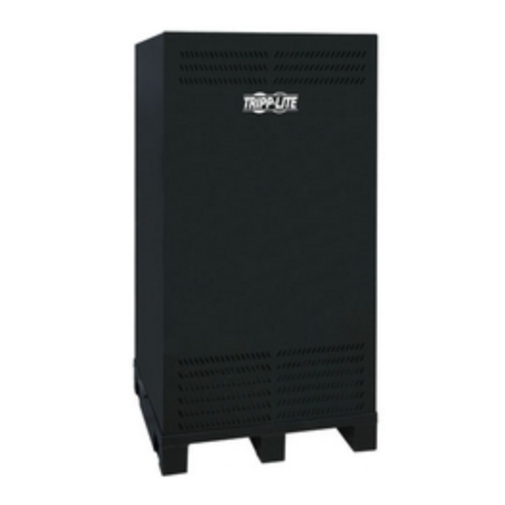
Extended-Run Single-Phase Battery Cabinet
Owner's Manual
Not suitable for mobile applications.
1111 W. 35th Street, Chicago, IL 60609 USA
+1.773.869.1234 • www.tripplite.com
2
3
5
5
5
5
6
6
6
7
7
7
8
9
9
9
9
9
10
10
10
11
11
12
13
14
14
14
15
15
Advertisement
Table of Contents

Summary of Contents for Tripp Lite Extended-Run Single-Phase Battery Cabinet
-
Page 1: Table Of Contents
Extended-Run Single-Phase Battery Cabinet 1. Introduction 2. Important Safety Instructions 3. Battery Cabinet Installation 3.1 Preparation 3.2 Transportation 3.3 Mechanical Check 3.4 Internal Wiring (Typical) 3.5 Preliminary Electrical Check 3.6 Battery Cabinet Placement 3.7 Electrical Connection 3.8 Battery Charger Electrical Connection (Select Models) 3.9 Final Electrical Check... -
Page 2: Introduction
1. Introduction Tripp Lite’s Extended-Run Single-Phase Battery Cabinets connect to SmartOnline 3-Phase UPS Systems to provide long-lasting battery backup for data centers, telecommunications, networks, industrial facilities, security, emergency systems and other mission- critical applications that require high capacity, high availability and extended runtime. -
Page 3: Important Safety Instructions
2. Important Safety Instructions SAVE THESE INSTRUCTIONS All sections of this manual contain instructions and warnings that must be followed during the installation and operation of the battery cabinet described in this manual. Read ALL instructions thoroughly before attempting to move, install or connect your battery cabinet. - Page 4 Allow batteries to charge uninterrupted for 24 hours after installation. • Do not attempt to service the integrated battery charger (included with “C” models only). Contact Tripp Lite if service is required. These symbols may appear on the product label: Refer to the product label for model numbers, voltage ratings and other important information.
-
Page 5: Battery Cabinet Installation
If the battery cabinet includes an integrated battery charger (“C” models only), examine the wires at the DC output terminal closely. If any of the leads are bent or otherwise damaged from shipping, contact Tripp Lite. Damaged leads could cause a battery short circuit. -
Page 6: Internal Wiring (Typical)
3. Battery Cabinet Installation 3.4 Internal Wiring (Typical) • Battery cabinets use multiple 12 VDC batteries connected in series to provide nominal DC voltages ranging from 192 VDC to 240 VDC. • Internal cabling is sized for specific application load currents. The insulated cables can be 2 AWG, 4 AWG, 2/0 AWG, 4/0 AWG or dual 2/0 AWG. -
Page 7: Electrical Connection
3. Battery Cabinet Installation 3.7 Electrical Connection DANGER! LETHAL HIGH VOLTAGE HAZARD! All wiring should be performed by a qualified electrician, in accordance with the warnings in this manual and all applicable electrical and safety codes. Incorrect wiring may cause serious personal injury and property damage. -
Page 8: Daisy-Chaining Multiple Battery Cabinets
3. Battery Cabinet Installation 3.10 Daisy-Chaining Multiple Battery Cabinets Additional battery strings can be daisy-chained to the UPS internal battery system via a unique connector inside the UPS battery compartment (Figure 3.10a). Battery Connection A 15-ft. BP240EXTNDR15DL cable is required to connect the first battery cabinet to the UPS system (Figure 3.10b). Cabling for all additional built-to-order cabinet installations is the sole responsibility of the electrician performing the installation. -
Page 9: Operation And Charging
4. Operation and Charging 4.1 Determine Charging Voltages To determine the appropriate equalization (freshening) charge voltage and float charge voltage, multiply the number of batteries connected in series in the battery cabinet by the recommended charging voltage per unit. For example: A +/- 240 VDC cabinet containing 40 each of the UPS12-400MR batteries in series would use the following charging voltages: Freshening/Equalization Charge Voltage = 20 x 14.4 VDC/unit average= +/- 288 VDC Float Charge Voltage = 20 x (13.5 to 13.8 VDC/unit average) = +/- 270 to 276 VDC... -
Page 10: Maintenance
5. Maintenance The battery cabinet contains valve-regulated recombinant lead-acid (VRLA) batteries, which are maintenance-free relative to the electrolyte. You cannot add water to these batteries or sample the electrolyte specific gravity. It is necessary, however, to periodically check the charging voltage, temperature and connections of the individual battery units. 5.1 Maintenance Schedule Quarterly Check Measure individual battery unit temperature. -
Page 11: Diagrams
6. Diagrams 6.1 Battery Cabinet Diagram (3 Shelves) 3.25 Battery Charger 4.50 4.50 Note: All dimensions are in inches. Battery Charger 6.00 6.00 32.4 Breaker 8.25 Mounting Plate AC Input for Battery Charger 16.00 11.00 4.00 10.58 3.50 14.50 29.00 28.80 15.40 13.50... -
Page 12: Battery And Breaker Diagrams
6. Diagrams ( continued ) 6.2 Battery and Breaker Diagrams 240 VDC Battery Diagram Shelf #2 Shelf 2 Shelf 3 Shelf #3 Shelf #1 (Bottom) Shelf 1 (Bottom) To Fuse or Breaker Termination To Fuse or Breaker Termination Notes: • All internal wiring is UL-listed, MTW, 125C Hi-Flex cable. •... -
Page 13: Integrated Battery Charger (Select Models)
6. Diagrams ( continued ) 6.3 Integrated Battery Charger (Select Models) Notes: • All dimensions are in inches. • AC input is preset with fuses for 120V 30 A, but can be rewired for 208 and 240 VAC, 60 Hz by a qualified electrician. •... -
Page 14: Specifications
7. Specifications 7.1 Dimensions and Floor Loading Battery Cabinet Model BP240V557C-1PH BP240V787C-1PH BP240V1037C-1PH BP240V1407C-1PH BP192V557C-1PH BP192V787C-1PH BP192V1037C-1PH BP192V1407C-1PH BP192V557C-16K BP192V787C-16K BP192V1037C-16K BP192V1407C-16K 7.2 Recommended Torque Battery Cabinet Model BP240V557C-1PH BP240V787C-1PH BP240V1037C-1PH BP240V1407C-1PH BP192V557C-1PH BP192V787C-1PH BP192V1037C-1PH BP192V1407C-1PH BP192V557C-16K BP192V787C-16K BP192V1037C-16K BP192V1407C-16K Dimensions Shelves (Width x Depth x Height) -
Page 15: Storage And Service
Regulatory Compliance Identification Numbers For the purpose of regulatory compliance certifications and identification, your Tripp Lite product has been assigned a unique series number. The series number can be found on the product nameplate label, along with all required approval markings and information. When requesting compliance information for this product, always refer to the series number. - Page 16 1111 W. 35th Street, Chicago, IL 60609 USA +1.773.869.1234 • www.tripplite.com 200809068 93-2847...


