Sony HDV HVR-1500 Operating Instructions Manual
Digital hd videocassette recorder
Hide thumbs
Also See for HDV HVR-1500:
- Service manual (274 pages) ,
- Brochure & specs (9 pages) ,
- Specification sheet (2 pages)
Table of Contents
Advertisement
Quick Links
Sony Corporation
Printed in China
Digital HD
Videocassette
Recorder
Operating Instructions
Before operating the unit, please read this manual
thoroughly and retain it for future reference.
The supplied CD-ROM includes Operating Instructions for the HVR-1500 digital
HD videocassette recorder (English, Japanese, French, German, Italian and
Spanish versions) in PDF format. For more details, see page 11, "Using the CD-
ROM Manual".
HVR-1500
© 2006 Sony Corporation
3-993-538-13 (1)
Advertisement
Table of Contents

Related Manuals for Sony HDV HVR-1500


Summary of Contents for Sony HDV HVR-1500
- Page 1 Before operating the unit, please read this manual thoroughly and retain it for future reference. The supplied CD-ROM includes Operating Instructions for the HVR-1500 digital HD videocassette recorder (English, Japanese, French, German, Italian and Spanish versions) in PDF format. For more details, see page 11, “Using the CD- ROM Manual”.
-
Page 2: Important Safety Instructions
Important Safety Instructions • Read these instructions. • Keep these instructions. • Heed all warnings. • Follow all instructions. • Do not use this apparatus near water. • Clean only with dry cloth. • Do not block any ventilation openings. Install in accordance with the manufacturer’s instructions. - Page 3 E1 (residential), E2 (commercial and light industrial), E3 (urban outdoors), E4 (controlled EMC environment, ex. TV studio) The manufacturer of this product is Sony Corporation, 1-7-1 Konan, Minato-ku, Tokyo, Japan. The Authorized Representative for EMC and product safety is Sony Deutschland GmbH, Hedelfinger Strasse 61, 70327 Stuttgart, Germany.
- Page 4 E1 (résidentiel), E2 (commercial et industrie légère), E3 (urbain extérieur) et E4 (environnement EMC contrôlé, ex. studio de télévision). Le fabricant de ce produit est Sony Corporation, 1-7-1 Konan, Minato-ku, Tokyo, Japon. Le représentant autorisé pour EMC et la sécurité des produits est Sony Deutschland GmbH, Hedelfinger Strasse 61, 70327 Stuttgart, Allemagne.
-
Page 5: Table Of Contents
Table of Contents Chapter 1 Overview Features... 8 Using the CD-ROM Manual ... 11 Names and Functions of Parts ... 12 Chapter 2 Preparations Before Using this Unit ... 25 Connecting an External Monitor ... 28 Superimposed Text Information... 29 Displaying Supplementary Status Information... - Page 6 Chapter 3 Recording and Playback Recording ... 41 Playback ... 45 Chapter 4 Using Time Data Recording Timecode and User Bit Data ... 51 Outputting Timecode... 54 Chapter 5 Connections and Settings for Editing Connection Using i.LINK... 55 Connections for a Linear Editing System ... 58 Chapter 6 Using the i.LINK Connector for Dubbing and TC Insert Digital Dubbing ...
- Page 7 Chapter 7 Menus Menu Organization ... 70 Menu Contents ... 73 Changing Menu Settings... 86 Assigning a Function to the ASSIGN Button ... 89 Appendix Important Notes on Operation... 91 Periodical Maintenance ... 92 Head Cleaning... 94 Troubleshooting ... 95 About i.LINK ...
-
Page 8: Chapter 1 Overview
The principal feature of this unit are as follows. 1) HDV and HDV logo are trademarks of Sony Corporation and Victor Company of Japan, Limited (JVC). 2) DVCAM is a trademark of Sony Corporation. -
Page 9: Variety Of Interfaces
RS- 422A interface or an optional SIRCS remote control unit such as the DSRM-10. 1) SIRCS (Sony Integrated Remote Control System): A command protocol to remote control Sony professional videocassette recorders/players. Internal and external timecodes... -
Page 10: Option Board
• Component video signal (Y, R-Y, B-Y) Analog audio signal input: XLR connector (female) These input signals can only be recorded in DVCAM/ DV(SP) format. Note Consult your Sony dealer or a Sony service representative for more information about purchasing and installing an option board. -
Page 11: Using The Cd-Rom Manual
Acrobat Reader. In such a case, install the latest version you can download from the URL mentioned in “Preparations” above. Note If you have lost or damaged the CD-ROM, you can purchase a new one to replace it. Contact your Sony service representative. Using the CD-ROM Manual... -
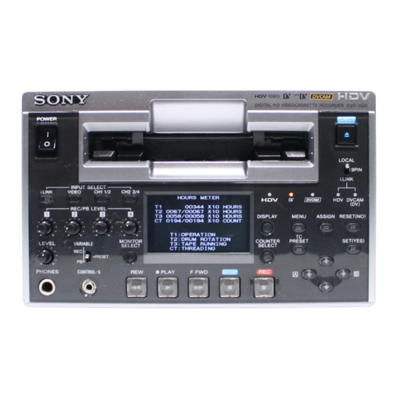
Page 12: Names And Functions Of Parts
Names and Functions of Parts Front Panel 1 POWER switch 2 MONITOR SELECT button 3 LEVEL knob 4 PHONES jack 5 CONTROL-S connector 1 Video/audio input selection section (see page 14) 2 Audio input/output level control section (see page 15) a POWER switch Press the “... -
Page 13: Display Button
When the audio level meters are displayed on the LCD monitor, the channel indicators below the level meters are highlighted to indicate the channel selection. c LEVEL (audio level adjustment) knob This adjusts the volume of the audio output from the PHONES jack. - Page 14 A Video/audio input selection section INPUT SELECT i.LINK VIDEO CH1 1/2 c CH1 1/2 button 2 VIDEO button 1 i.LINK button INPUT SELECT buttons a i.LINK button At the same time as selecting the i.LINK input, this button selects the recording format for i.LINK input recording. When pressed, the button itself lights, indicating that the i.LINK input (from the HDV/DV connector) is selected.
- Page 15 B Audio input/output level control section 1 REC/PB LEVEL control knobs REC/PB LEVEL VARIABLE PRESET 2 VARIABLE switch a REC/PB LEVEL (recording/playback audio level) control knobs These knobs used to control audio levels function differently depending on the setting of the VARIABLE switch as follows.
-
Page 16: Operation Mode
C LCD monitor Status display mode: 2 Audio level meters 3 Operation Small screen display mode: OVER OVER 12:34:56:00 a) You can switch the display on or off in the CHARA. DISPLAY menu item (see page 75). In this manual, both the LCD monitor of this unit and an externally connected monitor are referred to collectively as the “monitor screen”. - Page 17 operation when the audio recording mode selected on this unit does not coincide with that of the loaded tape. EDIT MODE: Lights when this unit is set in editing mode such as assemble editing or insert editing under the control of either an editing control unit connected to the REMOTE connector or device connected to the HDV/DV connector on the rear panel (see page 21).
-
Page 18: Output Signal Display
Notes • When i.LINK input is selected, the audio input signal is automatically input from the i.LINK connector, and no indicator is displayed in audio area. • Recording in HDV format is not possible when SG is selected. j Output signal display Indicates the output video and audio signal format selected with the INTERFACE SELECT menu items (see page 83). -
Page 19: Monitor Area
n Monitor area Displays the monitor video. o Superimposed text information Displays the text information and supplementary status information set in the menu. For details of superimposed text information, see “Superimposed Text Information” (page 29). 4 Remote control switch/indicator section 2 Remote control switch 1 Format indicators HDV DVCAM... -
Page 20: Tape Transport Control Section
Timecode display Operation to carry out Display the value of (point B Press the </A and ,/B timecode) - (point A timecode) buttons at the same time. F Tape transport control section 1 REW button a REW (rewind) button When you press this button, it lights and the tape starts rewinding. -
Page 21: Rear Panel
Rear Panel VIDEO IN Y/S-Y/CPST R-Y/S-C REF.VIDEO IN(SD/HD) Y/CPST OUT1 OUT2 MONITOR AUDIO 4 MONITOR AUDIO connector 4 Timecode input/output section (see page 24) 5 REF. VIDEO IN (SD/HD) (loop-through output) connectors a AC IN connector Use the specified power cord (not supplied) to connect this to an AC outlet. - Page 22 1 Analog video/audio signal input section (optional HVBK-1505 board required) The connectors in this section are available when the optional HVBK-1505 board is installed. 1 VIDEO IN connectors VIDEO IN Y/S-Y/CPST a VIDEO IN connectors (BNC type) There are the following VIDEO IN connectors for inputting analog video signals: •...
- Page 23 2 Analog video/audio signal output section Y/CPST a VIDEO OUT connectors, monitor output connector (BNC type) There are the following VIDEO OUT connectors for outputting analog video signals: • Y/CPST • Pr/R-Y/S-C • Pb/B-Y/S-Y The signals output from these connectors depend on the setting of the VIDEO OUTPUT menu item (see page 83).
-
Page 24: Digital Signal Input/Output Section
3 Digital signal input/output section 1 SDI IN connector a SDI IN (Serial Digital Interface input) connector (BNC type) This connector inputs digital video and audio signals in SDI format (SD). To select the required input signal formats, use the VIDEO button in the video/audio input selection section (see page 14). -
Page 25: Chapter 2 Preparations
Preparations Before Using this Unit Setting the System Frequency This unit is shipped with the system frequency still unset. Therefore, you need to set the system frequency before using the unit. (The unit cannot be used unless the system frequency is set.) Once it is set, the system frequency is retained even when the unit is powered off. -
Page 26: Menu Settings
• Items regarding interface (format) select • Items regarding the menu bank operations For details of each menu item, see Chapter 7, “Menus” (page 70). Menu settings Buttons used to change settings Use the following buttons in the menu control section to change the menu settings. -
Page 27: Using The Assign Button
Press the m button to select ENHANCED. S E T U P M E N U M E N U G R A D E : B A S I C * B A S I C E N H A N C E D Monitor screen Press the SET (YES) button. -
Page 28: Connecting An External Monitor
Sony dealer or a Sony sales representative. You can connect a video monitor to this unit’s video output connectors or to the MONITOR AUDIO connector. The following figure shows an example using a Sony LCD monitor. You can also superimpose character information such as timecode and the unit’s operating status on output video. -
Page 29: Superimposed Text Information
Superimposed Text Information The composite signals output from the (SUPER) CPST connector can contain superimposed text information, including timecode, menu settings, and alarm messages. To Turn Superimposed Text on and Set the DISPLAY CONTROL >CHARA. DISPLAY menu item (see page 75). ON: Display superimposed text. -
Page 30: Displaying Supplementary Status Information
Display Operation mode EDIT Edit mode (servo unlocked) EDIT LOCK Edit mode (servo locked) JOG STILL Still picture in jog mode JOG FWD Jog mode in forward direction JOG REV Jog mode in reverse direction SHUTTLE (Speed) Shuttle mode AUTO EDIT Automatic editing mode PREVIEW Preview mode... - Page 31 When the SUB STATUS menu item is set to TC MODE: On-screen indication Meaning INT PRST FREE [IP F] The internal timecode generator is operating in FREE RUN mode. INT PRST REC [IP R] The internal timecode generator is operating in REC RUN mode. INT REGEN-T&U The internal timecode generator is [IRTU]...
-
Page 32: Time Data Handled By This Unit
Time Data Handled by This Unit Using time data allows you to easily check time information, ensure high precision editing, and synchronize multiple devices. With this unit, you can use the following time data. Count value of the counter (CNT): relative position on the tape in frame units. - Page 33 You can set the display content of the superimposed text information, the type and positioning of the characters in the DISPLAY CONTROL menu item (see page 75). When the SUB STATUS menu item (see page 76) is set to anything other than OFF, you can display the supplementary status information relating to the editing mode and timecode generator.
-
Page 34: Recording Formats And Input/Output Signals
Recording Formats and Input/Output Signals Differences among HDV 1080i, DVCAM, and DV formats The following table illustrates differences among the features of the HDV 1080i, DVCAM, and DV formats. Item HDV 1080i Track width 10 µm Audio sampling 16 bit: 48 kHz (2 channels) 12 bit: 32 kHz (4 channels) frequency (maximum number of channels) Locked mode... - Page 35 Analog signal outputs YES: output present / NO: no output / –: does not apply Composite 6), 7) video Y/CPST Input signal Analog Composite signal inputs (HVBK-1505) 1), 2) Component S-video Analog audio Digital audio (AES/EBU) i.LINK DV format (DVCAM/DV) i.LINK HDV format (1080i) 1) With the HVBK-1505 analog input board (option) installed 2) It is not possible to input an HD component signal.
-
Page 36: Input Signals And Recording Formats
problem with the image when recording to tape on this unit. Input Signals and Recording Formats This unit can record in HDV format (1080/60i, 1080/50i), DVCAM format, and DV format (SP mode). YES: recording possible / NO: recording not possible Input signal Analog signal inputs Composite... -
Page 37: Playback Formats And Outputs
Playback Formats and Outputs The relationship between format and output signals during playback is as follows. Analog signal outputs YES: output present / NO: no output Composite 3), 4) video Y/CPST Recorded format on the tape DVCAM DV (SP) 1), 2) DVC-PRO (25 Mbps) DV (LP) 1080 60i... - Page 38 Digital signal outputs YES: output present / NO: no output SD-SDI Recorded format on the tape OUT1 DVCAM DV (SP) DVC-PRO 1), 2) (25 Mbps) DV (LP) 1080 60i 1080 50i 720 30P 1) Can be used in 525/60, 625/50 format. 2) DVCPRO format Cue track playback, and playback in a format other than 25 Mbps are not possible.
-
Page 39: Usable Cassettes
Usable Cassettes This unit can use the HDV/DVCAM cassettes listed below. The capacity of a standard cassette is 184 minutes of recording/playback, and that of a mini (S) cassette is 40 minutes. When DV (SP) format or HDV format is used, these recording/playback times are extended to 276 minutes and 60 minutes, respectively. -
Page 40: Inserting And Ejecting Cassettes
Paper clip, etc. Preventing accidental erasure Set the REC/SAVE switch on the cassette to SAVE to prevent accidental erasure of recorded contents. To enable re-recording Set the REC/SAVE switch to REC. Inserting and Ejecting Cassettes Inserting a cassette This unit accepts three sizes of cassette: Standard size (L), Medium size (M) (DVCPRO) and Mini size (S). -
Page 41: Chapter 3 Recording And Playback
Recording and Playback Recording This section describes the necessary settings and operations to perform recording on this unit. For details of connections and settings when using this unit as part of an editing system, see Chapter 5, “Connections and Settings for Editing” (page 55). For details of use for dubbing through the i.LINK interface, see Chapter 6, “Using the i.LINK Connector for Dubbing and TC Insert”... - Page 42 Select the formats of video and audio input signal to be recorded. Press the buttons in the video/audio input selection section to select the desired signal formats. Each selection is shown by a lit indicator in the input signal display. Video input Corresponding signal (input...
-
Page 43: Carrying Out Recording
analog audio signals are recorded on channels 1 and 3 and on channels 2 and 4, respectively. When manually adjusting audio input levels With the VARIABLE switch on the front panel set to REC, use the REC/PB LEVEL control knobs for each channel to adjust the audio input level. - Page 44 –12 dB is recommended. When dubbing DVCAM source material recorded at a different reference level, you can carry out manual adjustment as described in the following. Player (DSR- Recorder (HVR-1500) in 1800A/1800AP/ E-E mode 1600A /1600AP 1500A/1500AP) in...
-
Page 45: Playback
For details of use for dubbing through the i.LINK interface, see Chapter 6, “Using the i.LINK Connector for Dubbing and TC Insert” (page 64). Settings for Playback Video monitor HVR-1500 (this unit, player) POWER INPUT SELECT i.LINK VIDEO CH1 1/2... -
Page 46: Variable Speed Playback
For outputs from the PHONES jack and MONITOR AUDIO connector: Use the LEVEL control knob on the front panel (outputs from the PHONES jack on the front panel and the MONITOR AUDIO connector on the rear panel are adjusted). Note Except when down-converting a tape recorded in HDV format for output in DV or DVCAM format, it is not possible to adjust the audio signal level of the i.LINK... -
Page 47: Repeat Playback - Automatic Cyclical Playback
YES: output possible / NO: output not possible Playback Image Video output i.LINK speed quality ×24 Coarse ×8 Coarse ×1 Normal ×1/5 Normal ×1/10 Normal ×1/30 Normal Forward Normal frame-by- frame STILL Normal ×–1 Coarse ×–8 Coarse ×–24 Coarse Note Audio cannot be played back at variable speed for HDV format. - Page 48 Setting the current tape position as point A or B POWER INPUT SELECT i.LINK VIDEO CH1 1/2 CH2 3/4 OVER OVER REPEAT 1080 525 REC/PB LEVEL DISPLAY MENU VITC 44.1K MONITOR COUNTER PRESET LEVEL VARIABLE 01:23:45:15 SELECT EDIT MODE SELECT REC INHI PRESET PHONES...
- Page 49 S E T U P M E N U O P E R A T I O N A L F U N C T I O N R E P E A T F U N C T I O N R E P E A T M O D E : O F F R E P E A T T O P...
-
Page 50: Cuing Up To Any Desired Position Set As Point A Or B
If you want to discard the changed value Press the MENU button instead of pressing the SET (YES) button to return to the menu display, then press the MENU button again to end the menu operation without saving the changed value into memory. After the saving operation is completed, the monitor screen and time counter display return to the REPEAT FUNCTION setting display as shown in step 9. -
Page 51: Chapter 4 Using Time Data
Using Time Data Recording Timecode and User Bit Data For timecode recording, there are three methods, as follows. Internal preset mode: Set an initial value, and generate a timecode internally to this unit, which is recorded. You can select either of the following advance modes. •... -
Page 52: Recording Timecode To Continue From Previously Recorded Timecode
Set the TIME CODE menu items (see page 77) as follows, then press the SET (YES) button. Menu item Setting TC MODE INT PRESET RUN MODE FREE RUN ON (DF mode) or OFF (NDF mode) DF MODE 1)The internal TC (timecode) generator begins to advance at the instant of completion of the setting. -
Page 53: Synchronizing The Internal Timecode Generator To An External Timecode - External Synchronization
Synchronizing the Internal Timecode Generator to an External Timecode — External Synchronization External regen mode You can synchronize the internal LTC (Timecode signal connected to the TC IN connector, VITC signal inserted in the video signal, or RP188 LTC signal superimposed on SDI signal) generator to an external timecode (LTC) input to this unit. -
Page 54: Outputting Timecode
Outputting Timecode This section describes the timecode output from the TC OUT, VIDEO OUT and SDI OUT1/OUT2 connectors during playback and recording, and in E-E mode. Timecode Output During Playback Timecode output from the TC OUT connector (LTC) The timecode (and user bit data) read from the tape being played is output from the TC OUT connector. -
Page 55: Chapter 5 Connections And Settings For Editing
Note Production of some of the peripherals and related devices described in this chapter has been discontinued. For advice about choosing devices, please contact your Sony dealer or a Sony sales representative. Connection Using i.LINK Use in a Nonlinear Editing System... -
Page 56: Using In A Cut Editing System
Depending on the editing software used, this unit may not operate correctly. Before use, be sure to check that this unit is recommended as supported by the software. • The HDV/DV connector on this unit is 6-pin. Check the number of pins of the i.LINK (DV) connector of the connected computer and use an appropriate i.LINK cable. - Page 57 (recorder) settings INPUT SELECT menu item: i.LINK Remote control setting section: i.LINK button (lit) For details of DSR-2000A/2000AP settings, refer to the DSR-2000A/2000AP Operating Instructions. HVR-1500 (this unit, player) i.LINK Settings on this unit Remote control switch: i.LINK Connection Using i.LINK...
-
Page 58: Connections For A Linear Editing System
Connections for a Linear Editing System Notes When using this unit as the recorder for editing in DVCAM format: • It is not possible to carry edit audio channels separately. However, if all audio channels are selected, insert editing is possible. •... - Page 59 (SD/HD) IN(SD/HD) Y/CPST Pr/R-Y/S-C Pb/B-Y/S-Y OUT1 OUT2 OUT1 OUT2 HD-SDI HVR-1500 MONITOR AUDIO (this unit, recorder) MONITOR AUDIO a) To input analog video/audio signal requires the HVBK-1505. DSR-1500A/1500AP (player) settings RM-280 (editing controller) settings Settings on this unit LOCAL/REMOTE switch: REMOTE...
- Page 60 REMOTE I/F menu item: 9PIN Setting the VCR constants When connecting an editing control unit, make the settings each for HVR-1500 and DSR-1500A/1500AP as follows. In this case, the VCR constants need to be set each for HVR-1500 and DSR-1500A/1500AP. Set as follows.
-
Page 61: When Using This Unit As An Hdv Tape Player
BVE-700/700A editing control unit, with this unit as the player and an HDW-M2000/M2000P as the recorder. 175 Ω coaxial cable (not supplied) 29-pin remote cable (not supplied) HD-SDI OUT1,OUT2 HVR-1500 (this unit, player) AC IN AUDIO VIDEO IN Y/S-Y/CPST... - Page 62 Setup menu 10 R ST DLY: AUTO or LEARN Setup menu 11 P ST DLY: AUTO or LEARN Setting on this unit Remote control switch: 9PIN To the REMOTE connector of HVR-1500 REMOTE (9P) PLAYER (DEVICE 2) REMOTE (9P) DC IN REC TALLY...
-
Page 63: When Using The Editing Functions Of The Recorder
HD-SDI, and control signals are transferred via the REMOTE connector. 175 Ω coaxial cable (not supplied) 29-pin remote cable (not supplied) HD monitor HD-SDI input HVR-1500 HD-SDI (this unit, player) OUT1,OUT2 Reference video signal VIDEO... -
Page 64: Chapter 6 Using The I.link Connector For Dubbing And Tc Insert
HVR-Z1 as the player. Digital Dubbing Chapter HVR-Z1 (player) (4-pin) HDV/DV HVR-1500 (this unit, recorder) AC IN AUDIO VIDEO IN Y/S-Y/CPST R-Y/S-C REF.VIDEO VIDEO OUT... -
Page 65: Digitally Dubbing Signals In Hdv/Dvcam/Dv Format
Digitally Dubbing Signals in HDV/ DVCAM/DV Format Notes • The maximum recording time differs depending on the recording format even if using a tape with the same maximum recording/playback time (see page 39). To carry out dubbing, set the recording format to the format output from the player, or use a tape with longer maximum recording/playback time for recording. - Page 66 Dispaly Dubbing contents A/V [> A/V] Dub the audio and video. Note When A/V is selected, the timecode recorded follows the setting of the TIME CODE menu items (see page 77) in the setup menu. A/V/TC [> A/V/TC] Dub the audio, video, and timecode.
- Page 67 When carrying out A/V/TC/CM dubbing, if you press the STOP button to stop dubbing in step 8, or if dubbing stops because the source tape is longer than the recording tape, the above message appears to confirm whether or not to copy the contents of the cassette memory.
-
Page 68: Rerecording The Timecode - Tc Insert Function (Dvcam Format Only)
Rerecording the Timecode – TC Insert Function (DVCAM Format Only) The TC insert function makes it possible to use the internal timecode generator to rewrite timecode or user bit data when the timecode recorded on a tape is discontinuous. When recording in DVCAM format, you can start recording timecode from an initial value (see page 51) which can be set freely. -
Page 69: Dvcam Format
Note If the recording format is not DVCAM, a different message appears. For details, see “When recording format is not DVCAM” (page 69). Insert the cassette. A message to confirm the TC insert operation appears. T C I N S E R T : D V C A M S T A R T T C I N S E R T ? S T A R T : Y E S K E Y... -
Page 70: Chapter 7 Menus
Menus Menu Organization The menu system consists of three subsystems: SETUP MENU, AUTO FUNCTION (auto mode execution) menu and HOURS METER (digital hours meter display) menu. Pressing the MENU button displays the menu selection to set the desired menu item. This chapter mainly describes the SETUP MENU for the settings of functions. - Page 71 In the figure below, items shown in bold type are BASIC (basic items), and other items are ENHANCED (enhanced items). Menu organization Menu selection level SETUP MENU OPERATIONAL FUNCTION DISPLAY CONTROL TIME CODE TAPE PROTECTION (Continued) Level 1 Level 2 REPEAT FUNCTION AUTO EE SELECT LOCAL ENABLE...
- Page 72 Menu selection level (Continued) AUTO FUNCTION HOURS METER Menu Organization Level 1 Level 2 VIDEO CONTROL STILL MODE INT VIDEO SG STD/NON-STD OUT REF SEL SETUP REMOVE SETUP ADD CC(F1) BLANK CC(F2) BLANK WIDE MODE ESR MODE SD PROCESS CONTROL HD PROCESS CONTROL SYNC PHASE INPUT BLANK...
-
Page 73: Menu Contents
Menu Contents Setup Menu The purpose and settings of the setup menu items are described below. Indications of menu items and settings In the table below entitled “Menu contents”, the indication of each menu item or setting on the monitor screen is shown first, then the indication of the same item or setting in the time counter display of this unit is shown in square brackets ([ ]). - Page 74 OPERATIONAL FUNCTION [Operational]: Operation settings AUTO EE SELECT [> Auto CASSETTE OUT [>> Cass. EE]:Determine whether the unit enters EE mode or PB mode when audio and video signals from F. FWD/REW [>> F. FWD/ other equipment are input.When this unit is used as the recorder for cut editing, it is possible to output the input audio and...
- Page 75 OPERATIONAL FUNCTION [Operational]: Operation settings MAX SRCH SPEED [> Max SHUTTLE DV [>> SHUTL SRCH]: Specify the DV]: Set the maximum maximum tape speed in speed in search mode search (shuttle) mode and during DV/DVCAM format F.FWD (fast forward)/ playback. REW (rewind) mode.
- Page 76 DISPLAY CONTROL [Display]: Settings related to monitor display and indicators CHARA. POSITION [> Chara pos]: Set the position of text superimposed on output from the (SUPER) CPST connector to the monitor. CHARA. TYPE [> Chara type]: Set the type of characters in text superimposed on output from the (SUPER) CPST connector to the monitor.
- Page 77 DISPLAY CONTROL [Display]: Settings related to monitor display and indicators OVER DISP HOLD [> Hold OVER]: Determine whether or not to hold the OVER indication display on the audio level meters once the indications light. LCD [> LCD]: Adjust LCD BACK LIGHT [>>...
- Page 78 TIME CODE [Time code]: Settings related to the timecode generator TC SELECT [> TC select]: Determine which to display in the time counter display, TC or VITC. Note TC is always displayed regardless the setting during the HDV mode. VITC [> VITC]: Determine whether to record the internally generated timecode as VITC.
- Page 79 TIME CODE [Time code]: Settings related to the timecode generator MUTING IN SRCH [> Muting]: Select whether to suppress the output from the TC OUT connector in search (jog/ shuttle) mode. TAPE PROTECTION [Tape protct]: Settings related to tape and video head protection FROM STOP [>...
- Page 80 VIDEO CONTROL [Video]: Settings related to video control SETUP REMOVE [> Setup rmv]: Determine whether or not to remove black setup (7.5 IRE) from input analog video signals when converting them into digital signals. SETUP ADD [> Setup add]: Determine whether or not to add black setup to analog video output signals.
- Page 81 VIDEO CONTROL [Video]: Settings related to video control HD PROCESS CONTROL ADJ RANGE [>> Adj range]: [> HD Process] Select the adjustment range for video gain and chrominance gain. VIDEO GAIN [>> V gain]: Control the video output level. CHROMA GAIN [>> C gain]: Control the chrominance output level.
- Page 82 AUDIO CONTROL [Audio]: Settings related to audio control LEVEL SELECT [> Level Sel] REF LEVEL [>> REF Level]: CH1 IN LEVEL [>> CH1 CH2 IN LEVEL [>> CH2 OUTPUT LEVEL [>> Out INT AUDIO SG [> Audio SG]: Select the operation of the internal audio test signal generator.
- Page 83 AUDIO CONTROL [Audio]: Settings related to audio control JOG CONTROL [> Jog ctrl]: Select whether to adjust the audio playback speed during slow playback. Note This setting is invalid when playing back in HDV format. MUTING IN SHTL [> Shutl mute]: Set the audio muting conditions during shuttle playback.
- Page 84 INTERFACE SELECT [Interface]: Settings related to external interfaces i.LINK OUTPUT [> i.Link Out]: When playing a tape recorded in HDV format, set the format output from the connector. Note Before changing the setting, either temporarily disconnect the i.LINK cable or power off the connected device. DOWN CONVERTER [>...
-
Page 85: Auto Mode (Auto Function) Execution Menu
MENU GRADE [Menu grade]: Selection of menu items to be displayed Determine whether to display basic items only or both basic and enhanced items on the monitor screen and in the time counter display when using the menu. Auto Mode (AUTO FUNCTION) Execution Menu The following table shows the purpose and function of the items in the auto mode execution menu. -
Page 86: Changing Menu Settings
Changing Menu Settings This section explains how to change menu settings. Buttons Used to Change Settings Use the following buttons in the front panel to change the menu settings. Menu control Functions buttons MENU button • Opens the menu and launches menu control mode. - Page 87 Example: Display when DISPLAY CONTROL is selected S E T U P M E N U O P E R A T I O N A L F U N C T I O N D I S P L A Y C O N T R O L T I M E C O D E S E T U P B A N K O P E R A T I O N S Y S T E M S E L...
-
Page 88: Displaying Enhanced Menu Items
On-screen indication Meaning Character string at the right Current setting of the menu of a menu item item When shown with a colon (:): the current setting is the When shown with a An asterisk in a complete Factory default setting list of settings See step 6 of the foregoing operating procedure. -
Page 89: Assigning A Function To The Assign Button
Press the RESET (NO) button. The factory default setting of “x 1” is selected. Press the SET (YES) button. The setting returned to its factory default is saved in memory as the current setting. To return all settings to their factory default settings Press the MENU button to display the menu selection level. - Page 90 S E T U P M E N U O P E R A T I O N A L F U N C T I O N D I S P L A Y C O N T R O L T I M E C O D E S E T U P B A N K O P E R A T I O N S Y S T E M S E L...
-
Page 91: Appendix
Appendix Important Notes on Operation On safety • Should any liquid or solid object fall into the cabinet, unplug the unit and have it checked by qualified personnel before operating it further. • Unplug the unit from the wall outlet if it is not to be used for an extended period of time. -
Page 92: Periodical Maintenance
These counts can be displayed on the monitor screen and in the time counter display of this unit. Use them as guidelines for scheduling maintenance. In general, consult your Sony dealer about necessary periodic maintenance checks. Digital hours meter display modes The digital hours meter has the following four display modes. - Page 93 Drum 0000 T3 (TAPE RUNNING) mode: Tape 0000 CT (THREADING) mode: Thread 0000 To end the digital hours meter display Press the MENU button. To reset the trip values About this operation, consult your Sony dealer. 0000/00000 0000/00000 0000/00000 Periodical Maintenance...
-
Page 94: Head Cleaning
Head Cleaning Always use the PDVM12CL (mini size) or PDV12CL (standard size) Cleaning Cassette to clean the video and audio heads. You can run the cleaning cassette for 10 seconds per cleaning operation. Follow the instructions for the cleaning cassette, as inappropriate use of the cleaning cassette can damage the heads. -
Page 95: Troubleshooting
Troubleshooting If an alarm message appears on the monitor screen, or if the unit appears to be malfunctioning, please check the following before contacting your Sony dealer. Tape problems Cause Symptom Recording is not possible. The cassette’s REC/SAVE switch is set to SAVE. -
Page 96: Alarm Messages
Monitor problems Cause Symptom Data is not superimposed on The CHARA. DISPLAY menu the monitor screen. item is set to OFF. The monitor is not connected to the (SUPER) CPST connector of this unit. The 75 Ω termination switch The image on the monitor screen is too bright. - Page 97 (Cause) A non-standard ref. signal is being Use a standard signal. used for REF. VIDEO. Abnormal settings selected in setup Correct the setup menu settings. Contact your Sony menu. dealer if this alarm message appears again after making corrections. −...
-
Page 98: Error Messages
Direction When an error message appears, follow the instructions on the monitor screen for resolving the problem. Error02-603 When an error message persists, contact your Sony dealer Time counter display or a Sony service representative. Alarm message in time counter... -
Page 99: About I.link
IEEE 1394 proposed by Sony, is a trademark supported by many companies worldwide. IEEE 1394 is an international standard defined by IEEE, the Institute of Electrical and Electronics Engineers, Inc. -
Page 100: Specifications
Specifications General Signal system 1080/60i format, NTSC color, EIA standard 1080/50i format, PAL color , CCIR standard Power requirements 100 V to 240 V AC, 50/60 Hz Power consumption (with all options installed) 60 W Peak inrush current (1)Power ON, current probe method: 12 A (100 V), 34 A (240 V) (2)Hot switching inrush current, measured in accordance with... -
Page 101: Processor Adjustment Range
Band width (625/50) Composite/S-video: 25 Hz to 4.8 MHz ±1.0 dB (Y) Component : 25 Hz to 5.0 MHz ±1.0 dB (Y) 25 Hz to 2.0 MHz +1.0/ − 2.0 dB (R − Y/B − Y) Composite/S-video I/O (Y): 52 dB or more Component I/O (Y): 54.5 dB or more Y/C delay 30 ns or less... - Page 102 STORAGE SYSTEMS TO RECORD CONTENT OF ANY TYPE. • Always verify that the unit is operating properly before use. SONY WILL NOT BE LIABLE FOR DAMAGES OF ANY KIND INCLUDING, BUT NOT LIMITED TO, COMPENSATION OR REIMBURSEMENT ON ACCOUNT OF THE...
-
Page 103: Glossary
Glossary A/B roll editing An editing method that uses two or more playback VCRs to create special effects such as dissolve and wipe, and uses one record VCR to record the results of the editing. Using an editing control unit allows efficient control of the VCRs and very precise editing. - Page 104 video and digital television transmission, it maintains high image quality while achieving high compression ratios, using predictive techniques for capturing motion. Non-drop frame mode A mode of advancing timecode which ignores the difference in frame values between real time and the timecode.
- Page 105 base correction reduces deterioration of picture quality when transmitting or copying playback signals. Threading See “Loading.” Timecode A digitally encoded signal which is recorded with video data to identify each frame of the video by hour, minute, second and frame number. SMPTE time code is applied to NTSC system, and EBU time code to PAL and SECAM systems.
-
Page 106: Index
Index AC IN connector 21 Alarm messages 96 Analog audio inputs 101 audio outputs 102 interfaces 9 video inputs 101 video outputs 101 Analog video/audio signal input section 22 Analog video/audio signal output section 23 Arrow buttons 19 ASSIGN button 13, 89 Audio performance 101 AUDIO (AES/EBU) IN 1/2, 3/4... - Page 107 REF. VIDEO IN (SD/HD) connector Remote control 9, 46 control connectors 102 control switch 19 REMOTE connector 21 Remote control switch/indicator section 19 REPEAT indicator 17 Repeat playback 47 RESET (NO) button 13 REW button 20 SDI IN connector 24 SDI OUT1, OUT2 connectors 24 Servo lock indicator 20 SET (YES) button 13...