Table of Contents
Advertisement
Advertisement
Table of Contents

Related Manuals for Sekonic L-758C


Summary of Contents for Sekonic L-758C
- Page 1 DIGITALMASTER L-758DR L-758D L-758 Operating Manual...
- Page 2 Blank page...
-
Page 3: Safety Precautions
Before using your light meter, please read this “Safety Precautions” carefully and use it properly. WARNING CAUTION NOTE: Reference: Provides the reference information and related functions WARNING • Please place light meter in a location where an infant cannot reach and accidentally get the strap wrapped around his or her neck. -
Page 4: Table Of Contents
Table of Contents Safety Precautions Table of Contents 1. Parts Designation ... 1 1. Light Meter Parts ... 1 2. Supplied Accessories ... 2 2. Explanation of the Liquid Crystal Display(LCD) ... 3 3. Before Using ... 7 1. Attach the strap ... 7 2. - Page 5 7. Camera Exposure Profiling ... 42 1. Calibration testing for exposure profiling ... 42 2. Input test target data ... 44 2-1 Sekonic Application software ... 44 2-1-1 Outline of software ... 44 2-2 Manual Exposure Profile Input ... 45 3.
- Page 6 Table of Contents 10.Care and Maintenance ... 56 FCC & IC compliance information ... 57...
-
Page 7: Parts Designation
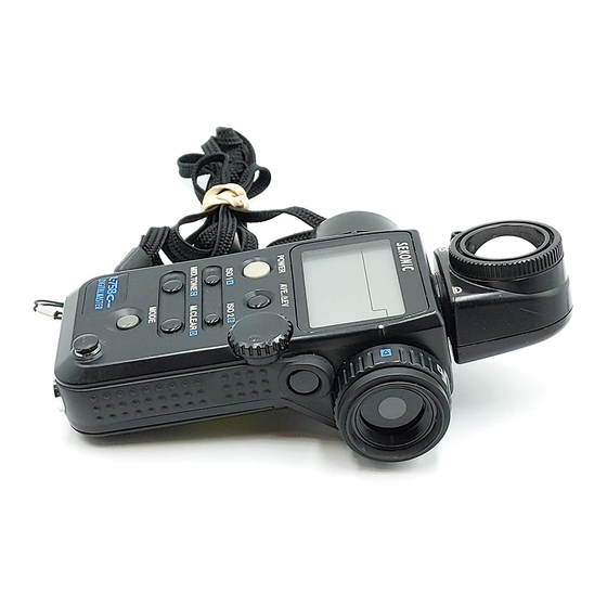
Light Meter Parts !8 S pot Lens ⑦ Memory button* ⑫ Power button (ON/OFF switch) @1 U SB Port ⑪ ISO 1 button (“A” in radio channel setting) ⑳ Mid-Tone button ("C" in radio channel setting) ⑩ Mode button ⑨ Strap eyelet @ 4 1 /4”... -
Page 8: Supplied Accessories
1. Parts Designation Supplied Accessories @6 S ynchro Terminal Cap (Attached to meter) @ 8 L ens Cap (Attached to meter) # 0 C D-ROM for Software (Data Transfer Software, USB driver, Operating manual and Software guide) # 2 Q uick Guide (in Japanese/English) # 4 B attery (CR-123A) @ 7 S trap @9 U SB Cable... -
Page 9: Explanation Of The Liquid Crystal Display(Lcd)
2. Explanation of the Liquid Crystal Display (LCD) LCD for L-758DR/L-758D LCD for L-758CINE NOTE: For explanation purposes, the display illustrated here shows all icons and readouts simultaneously. Actual LCD screen will not show all icon as above during normal use. - Page 10 2. Explanation of the Liquid Crystal Display Display in viewfinder In setting : ⑧ Flash analyzing : ④ Luminance : *Not displayed in Incident reading. ① Measuring Mode Icons Ambient (see page 15) Auto-Reset Cordless Flash (see page 22) Cord Flash (see page 21) Wireless flash radio triggering mode (see page 28) ②...
- Page 11 ⑦ Analog Scale Displays measured values as icons along the apertures or Latitude EV scale. The scale is graduated in full or 1/3 stop increments for measurements. Memorized and averaged values are also display along the scale. • Aperture scale (upper scale) displays in all mode except Aperture priority mode. f 0.7 to f 90 in full stops appears in all modes except aperture priority mode (L-758) f 0.5 to f 64 in full stops appears in all modes except aperture priority mode (L-758CINE) •...
- Page 12 2. Explanation of the Liquid Crystal Display ⑭ Shutter angle (L-758CINE) Appears when shutter angle is set to a value other than 180 degrees (see page 19) ⑮ Illuminance mark / Luminance mark (L-758CINE) Appears when Foot-Candle is selected Appears when Lux is selected Appears when Foot-Lambert is selected Appears when cd/m is selected...
-
Page 13: Before Using
Attach the strap Attach the Strap @7 by passing the small loop end through the eyelet ⑨ and passing the other end of strap through it. WARNING • To avoid a danger of strangulation, please keep the strap in a location where an infant cannot reach it and accidentally get the strap wrapped around his or her neck. -
Page 14: Replacing The Battery During Measurement Or When Using The Memory Function
3. Before Using Replacing the battery during measurement or when using the memory function Always turn the power OFF before replacing the battery. If the battery is removed with the power ON, measurements and settings in memory can no longer be recalled. If after replacing the battery, or during measurements, strange screens (displays that have not been set) appear on the LCD, or nothing happens, no matter what button is pushed, remove the battery and wait at least ten seconds and then replace the battery. -
Page 15: Jog Wheel Lock Or Lock Off
Jog Wheel Lock or Lock Off 1. Hold down the Mode button ⑩ and ISO1 button ⑪ and “LOC” will appear to indicate that the Jog Wheel is locked. The last measurement is held until the lock is released, even if the Jog wheel ⑤ is accidentally moved. -
Page 16: Setting The Measuring And Memory Button Configuration
3. Before Using Setting the Measuring and Memory button configuration In the custom settings mode (refer to P40), the Measuring button and the Memory button can be set as follows. 1. For Incident measuring The Measuring button and Memory button is set in the standard configuration. -
Page 17: Basic Operation
Incident or reflected spot measuring To set for either incident or reflected light operation, turn the Incident / Reflected Spot Selector Dial ⑲ on the eye piece, to the desired position ( Incident operation When incident operation is selected, the Spot operation is selected the Incident operation NOTE:... -
Page 18: Setting Measuring Mode
4. Basic Operation Setting measuring mode Hold down the Mode button ⑩ and turn the Jog wheel ⑤ to select the desired mode. The mode switching sequence is shown in the chart below: Shutter Speed Priority mode (Available light) See page 15 Aperture Priority mode (Available light) See page 17... -
Page 19: Incident Measurement Mode
Incident Measurement Mode Incident light measuring is the measurement method that employs either the Lumisphere or Lumidisc functions. Measurements should be with the Lumisphere aimed towards the camera direction from the subject position. You can select extended or retracted lumisphere measuring positions by rotating the Lumisphere retracting ring ①... -
Page 20: Reflected Measurement Mode (Spot Metering)
4. Basic Operation Reflected Measurement Mode (spot metering) This method measures the brightness (luminance) of the light reflected from the subject. It is useful for distant objects such as landscapes, when you cannot go to the position of the subject, or for metering subjects that generate light (neon signs, etc.), highly reflective surfaces or translucent subjects (stained glass, etc.). -
Page 21: Measurement
Measuring ambient light In this measurement mode, we have the choice of shutter priority mode, aperture priority mode or EV mode. Hold down the Mode button ⑩ and turn the Jog wheel ⑤ to select ambient measurement mode 1-1 Shutter Speed Priority mode Hold down the Mode button ⑩... - Page 22 5. Measurement • “E.u” (Exposure under) or “E.o” (Exposure over) appears when the combination of shutter speed and aperture is outside the display range. ☆ When E.O (Exposure Over) is displayed,it indicates that the measured exposure is outside the display range, changing the shutter speed to a faster setting with the Jog wheel will allow you to find a combination of proper aperture and shutter speed.
-
Page 23: Aperture Priority Mode
1-2 Aperture Priority mode 1. Hold down the Mode button ⑩ and turn the Jog wheel to select aperture priority mode 2. Turn the Jog wheel ⑤ to set the desired f stop value. 3. Press the Measuring button ⑭ to take a measurement. -
Page 24: Ev Mode
5. Measurement 1-3 EV mode 1. To activate EV mode, please set Custom setting no.5 and Item no.1. (See page 40) 2. Hold down the Mode button ⑩ and turn the Jog wheel ⑤ to select EV mode 3. Press the Measuring button ⑭ to take a measurement. -
Page 25: Cinematography
1-4 Cinematography 1. Hold down the Mode button ⑩ and turn the Jog wheel ⑤ to select ambient light shutter speed priority mode 2. Turn the Jog wheel to select the Cine Speed for the camera that will be used. Cine Speed are displayed after 1/8000, 1/200, 1/400 and the unit is in frames per second (f/s). - Page 26 5. Measurement 4. Setting the shutter angle (L-758CINE only). It is possible to set the shutter angle by turning the Jog wheel ⑤ while pressing Mode button ⑩ and ISO2 button ⑥ . Note: • Shutter angle: The angle can be set in the range of 1°to 10° (in 1° steps), 15° - 270° (in 5°...
-
Page 27: Measuring Electronic Flash
Measuring electronic flash This method of measurement can be done in the following modes; with cord, without cord, and Wireless flash radio triggering mode (cumulative or non-cumulative). When Measuring flash light, the shutter speed and F stop value (value combining ambient light and flash light: total amount of light) are displayed. -
Page 28: Auto-Reset Cordless Flash Mode
5. Measurement WARNING: • To avoid a danger of choking, please place Synchro terminal cap in a location where an infant cannot reach and accidentally swallow it. CAUTION: • There is danger of electric shock if the meter is handled with wet hands, during rain, in areas splashed by water or where there is a lot of moisture. - Page 29 3. When the Measuring button ⑭ is pressed, the mode mark will blink and the meter is ready to measure. The ready to measure mode will continue for approximately 90 seconds. During this time, trigger the flash to make a measurement.
-
Page 30: Cord Multiple Flash (Cumulative) Mode
5. Measurement 2-3 Cord multiple flash (cumulative) mode These measurements are used when the light generated by the flash is inadequate for proper exposure. The repeated flash pops can be accumulated until the desired aperture is displayed. The cumulative number is infinite. Only one digit is displayed if the cumulative number is ten or more. -
Page 31: Cordless Multiple Flash (Cumulative) Mode
CAUTION: • There is danger of electric shock if the meter is handled with wet hands, during rain, in areas splashed by water or where there is a lot of moisture. Under such conditions, it is recommended that you use the meter in the cordless flash mode, or wireless flash radio triggering mode and keep the Synchro terminal cap in place. - Page 32 5. Measurement 2. When the light from the flash is received, the measured value (f stop) is displayed. Each time this is repeated, the accumulated value for the aperture and the number of cumulative flashes is displayed. 1st. time 3. The ready to measure mode will be displayed for approximately 90 seconds. If the 90 second period is exceeded and the blinking mark stops, press the Measuring button ⑭...
-
Page 33: Flash Analyzing Function
Reference: • Slower shutter speeds allow more available light to reach the film or digital camera sensor, and faster shutter speeds reduce the amount of available reaching the film or sensor. • The settings above are made by adjusting the ambient light by the shutter speed. It is also possible to modify the ratio by adjusting the flash light (when changing the distance between the flash and the subject or when changing the amount of light of the flash). -
Page 34: Wireless Flash Radio Triggering
5. Measurement 2-6 Wireless Flash Radio Triggering With the Radio Transmitter module plugged into the meters radio socket and a Receiver or Transceiver (PocketWizard a convenient system that enables one person working alone to measure flash output without the need of a sync cord. Pressing the Measuring button simultaneously triggers the flash and measures the flash output simultaneously. - Page 35 4. In the Quad-Triggering zone setting, after the channel is set to 17 to 32, the assigned buttons below are pressed. Pressing each of the buttons activates or deactivates the Quad- Triggering zone (A, b, c or d). When a Quad-Triggering zone is activated, the corresponding Quad-Triggering zone letter appears on the display.
- Page 36 5. Measurement Reference: • Refer to the radio Receiver or Transceiver instruction manual for the recommended operating method. • Maximum distance of the radio flash triggering system can vary depending on the placement of the remote Receiver or Transceiver, direction of the radios antenna, distance from a large body of water or concrete wall and other possible factors.
-
Page 37: Advanced Functions
Memory function This meter can store up to nine measured values in memory for incident light and reflected light simultaneously. This feature can be used in the following modes; Ambient light : shutter speed priority, aperture priority or EV mode. Electronic Flash light : cord, cordless or wireless flash radio triggering mode. -
Page 38: Averaging Function
6. Advanced Functions Averaging function This function displays the average of up to nine of the values in memory. Press the Measuring button ⑭ and take a meas- urement. Current measured value on the analog scale will blink. Press the Memory button ⑦ and store the measured value in memory, and memorized value on the analog scale stops blinking. - Page 39 Turn any secondary light source off. Point the Lumisphere toward the main light source, from the position of the subject and take a measurement. Press the Memory button ⑦ and store the value in memory. EV button ④ and display the “A”mark Press the AVE./ on the LCD indicating a standard value.
-
Page 40: How To Use An Incident Illuminance (Lux Or Fc) Meter (L-758Dr/758D)
6. Advanced Functions How to use an incident illuminance (LUX or FC) meter (L-758DR/758D) Turn the Lumisphere retracting ring ① to lower it to the (retracted) mark position. Make sure that any compensation Exposure/Calibration compensation: see page 36 & 37, Compensation of camera exposure profile: see page 46 is canceled. -
Page 41: How To Use A Reflected Luminance (Cd/M Or Fl) Meter (L-758Dr/758D)
How to use a reflected luminance (cd/m Exposure/Calibration compensation: see page 36 & 37, Compensation of camera exposure profile: see page 46. Set the meter to EV mode and ISO 100. Set meter to spot reading for reflected light. Take the measurement by looking through the finder and aligning so the subject that will be measured is inside the circle. -
Page 42: How To Use The Exposure Compensation Function
NOTE: • When making compensations, be sure that it satisfies your needs based on the results of your digital camera sensor or film be used. • While incident and reflected light can be set independently, be aware that both ambient light and flash exposure are corrected uniformly. -
Page 43: How To Use Calibration Compensation Function
NOTE: • When making calibration compensations, be sure that it satisfies your needs based on the results of digital camera sensor or film being used. • While incident and reflected light can be set independently, be aware that both ambient light and flash exposure are corrected uniformly. -
Page 44: Filter Compensation
6. Advanced Functions Filter compensation 8-1 Filter compensation (1) It is possible to compensate for filter factor within a range of 5.0 EV in 1/10 steps. The measurement corresponding to the set compensation and can be displayed while pressing ISO2 button ⑥ . Highlight and shadow compensation values can also be enter for quick exposure metering. -
Page 45: Filter Factor Number Compensation (2) (L-758Cine Only)
8-2 Filter factor number compensation (2) (L-758CINE only) When using the L-758DR for Cine/Video exposures, in cine industry, it is possible to set 7 different frequently used types of filters. Select setting number 1 and item number 2 in the custom setting mode (see page 40). The symbol of the desired filter from among the 7 types can be selected by turning the Jog wheel ⑤... -
Page 46: Custom Setting Function
6. Advanced Functions Custom setting function The following Custom Settings provide a quick and easy setup of individual meter preferences. All preferences are stored on a memory chip and can not be deleted, they can only be changed back to default settings. - Page 47 To enter the custom setting mode, the meter must first be turned off. Press Mode button ⑩ and turn the power on. In the custom setting mode, ‘CS’ (custom setting) is displayed in the ISO display area, a setting number between 01-14 (L-758DR/758D) or 01-17 (L- 758CINE) is displayed in the shutter speed display area and item number 0, 1, 2 or 3 is displayed in the...
-
Page 48: Camera Exposure Profiling
The L-758DR (L-758D/L-758CINE) can be pro- grammed to match the sensitivity of film or digital camera sensor for prefect exposure control. In addition, since film and digital cameras have their own unique dynamic range, clipping point (expo- sure tolerance) and varying ISO sensitivity they need to be profiled. - Page 49 It is necessary to test the cameras sensitivity, measure the actual dynamic range and know the clipping points of your digital camera and/or type of film and processing used before programming the L-758DR (L-758D/L-758CINE) meter for Exposure Profiling. Film exposures should be evalu- ated by scanning the film first and then evaluating the images in a photo application software.
-
Page 50: Input Test Target Data
Input test target data There are two ways to input the result of the test target data into the light meter: 1) Sekonic Data Transfer Software - install application software from the included CD-ROM and connect the com- puter and light meter via USB, and 2) Direct Input - Manually enter the test target data directly into the light meter. -
Page 51: Manual Exposure Profile Input
2-2 Manual Exposure Profile Input It situations where it is not possible or convenient to use a computer or the Sekonic Data Transfer Software, Exposure Profile data can be entered into the L-758DR (L-758D or L-758CINE) directly. Below is the step by step process for manually entering a specific Exposure Profile. - Page 52 7. Camera Exposure Profiling 7) Setting compensation value Rotate the Jog wheel ⑤ while holding down ISO1 button ⑪ and ISO2 button ⑥ simultaneously. Compensation values can be made in 1/10 step increments in +/-5.0EV. 8) Setting Clipping point (-) Rotate the Jog wheel ⑤...
- Page 53 11) Setting Clipping point (+) Rotate the Jog wheel ⑤ while pressing ISO2 but- ton ⑥ . Clipping point can be set from 0 to +7EV in 1/10 step increments. 12) Press the Measuring button ⑭ if you want to copy this ISO setting to all ISO setting (from ISO 3 to 8000) Reference:...
-
Page 54: How To Use Exposure Profiling Mode
7. Camera Exposure Profiling How to use Exposure Profiling mode 3-1 Selecting Camera Exposure Profiling Preset Camera Exposure Profiles (Camera 1, 2 and 3) can be recalled. 1) Press and hold down the ISO 1 button ⑪ ,while pressing the MID.TONE button ⑳ to select the desired Camera profile (Camera 1, 2 or 3). -
Page 55: Mid.tone Button
2) The EV scale displays Clipping points(+/-),Dy- namic range(+/-)and Mid. Tone with a triangle " "icon. 3) Measured value exceeding Dynamic range will be displayed as a slow blinking " icons.Measurements that exceed the clipping points will be displayed as fast blinking " icons. - Page 56 7. Camera Exposure Profiling 2) After setting the Mid.Tone (ex.Incident reading), take measurements (highlight or shadow, etc. with spot reading) and memorize them to see if measurements are within Dynamic range or Clipping points. Mid. Tone F5.6 3) Adjusting Mid.Tone Value If it becomes necessary to change the measured mid-tone value, press and hold down the MODE button while pressing the MID.TONE button (M 0 will start to blink) this will lock the mid-tone value on the scale.
- Page 57 4) Setting Mid.Tone Value from Memorized Values After taking three or more reflected Spot measurements, select which memorized value on the analog scale should be the Mid-Tone value. First enter the memory recall mode by pressing and holding the MODE button, while pressing the Memory button. Select one of the memorized values by rotating the Jog wheel and press the MID.TONE button to set it as the Mid-tone value.
-
Page 58: Optional Accessories
This is a Gray Scale Test target for Exposure Profiling and meter calibration. (The size is 260 x 160mm. 10.2” x 6.3”). One side is nine gray patches including black and white, and the other side is an: 18% gray card for digital camera white balancing and spot metering. -52-... - Page 59 • PocketWizard and Sekonic’s Radio Triggering system may be used only in countries where a permit for the approved frequency has been issued by the government office in charge.
-
Page 60: Technical Data
9. Technical Data · Type · Light receiving method · Light Receptors Incident light Reflected light · Light receptor element · Metering modes Ambient light Flash · Measuring Range (ISO 100) Ambient light Incident light Reflected light Flash Incident light Reflected light Illumination (direct measurement is possible only in 758CINE) Brightness (direct measurement is possible only in 758CINE) - Page 61 Aperture Analog scale Contrast function Shutter angle (758CINE only) Filter compensation Filter factor number compensation (758CINE only) Multiple Flash function Exposure compensation Calibration compensation : +/- 1.0 EV (in 1/10 steps) Flash analyzing function · Other features All-weather feature Memory function Memory clear •...
- Page 62 This will cause inundation, corrosion or malfunction. • If the rubber seal’s surface is damaged,water or moisture may enter and damage the meter. If this has happened, you must send your meter to the Sekonic Sevice Center in your country.
- Page 63 Warning: Changes or modifications to this unit not expressly approved by the party responsible for compliance could void the user's authority to operate the equipment. Note: This equipment has been tested and found to comply with the limits for a Class B digital device, pursuant To Part 15 of the FCC Rules.
- Page 64 -58-...
- Page 65 Memo -59-...
- Page 66 Memo -60-...
- Page 67 Blank page...
- Page 68 7-24-14, OIZUMI-GAKUEN-CHO, NERIMA-KU, TOKYO 178-8686 JAPAN TEL:+81 ( 0 ) 3-3978-2335 FAX:+81 ( 0 ) 3-3978-5229 http://www.sekonic.co.jp JH1297563...