Advertisement
Quick Links
Applied Machines: C652/C552/C452
COLOR MFP: 65 ppm/55 ppm/45 ppm
Product Code: A0P0/A0P1/A0P2
I. Accessory parts
No.
Name
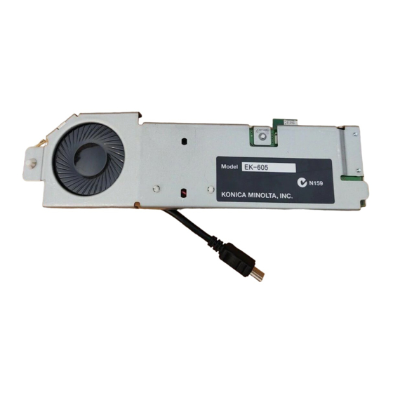
1. Local interface
board unit
2. Screw
(3 × 6 mm)
3. Label
4. Installation
manual
After unpacking, be sure to get rid of the
packaging materials and keep them out of
the reach of children.
Putting the head in the plastic bag
involves danger of suffocation.
Note:
When installing the keyboard, connect its cable to
the USB port added to the machine.
EK-604/EK-605
INSTALLATION MANUAL
Shape
Q'ty
1
A0YCIXC001DC
1
9646
1
A0YCIXC003DA
1 set
4980IXC019DA
Local Interface Kit
II. Installation procedures
1. Turn off the machine and unplug the power cord
from the power outlet.
2. Remove the IR upper front cover from the
machine (three screws).
3. Remove the cap from the cover on the main body
as shown in the illustration below.
E-1
A0YCIXC004DC
A0YCIXC005DB
A0YC-9550-01
Advertisement

Related Manuals for Konica Minolta EK-604

Summary of Contents for Konica Minolta EK-604
- Page 1 EK-604/EK-605 Local Interface Kit INSTALLATION MANUAL Applied Machines: C652/C552/C452 COLOR MFP: 65 ppm/55 ppm/45 ppm Product Code: A0P0/A0P1/A0P2 I. Accessory parts II. Installation procedures 1. Turn off the machine and unplug the power cord Name Shape Q’ty from the power outlet.
- Page 2 4. Remove the cover from the main body as shown 7. Disconnect the connector to remove the USB below (one screw). unit. A0YCIXC006DB A0YCIXC009DA 5. Remove the blind cover from the cover removed 8. Remove the USB cable from the local interface in step 4 (one screw).
- Page 3 10. Connect the connector removed in step 7 to the 13. Insert the two cables connected to the local interface board unit. interface board unit into the wire saddle. Wire saddle A0YCIXC011DB A0YCIXC014DB 11. Remove the connector from the wire saddle 14.
- Page 4 III. Affixing the label 15. Install the local interface board unit. Put the dowel into the hole and fix the unit with one Affix the label furnished with the local interface kit to screw. the position shown below. Note: • Be sure to put the hook on the local interface board unit into the positioning hole on the main body.