Panasonic AG-HMX100E Operating Instructions Manual
Digital av mixer
Hide thumbs
Also See for AG-HMX100E:
- Operating instructions manual (37 pages) ,
- Operating instructions manual (93 pages) ,
- Operating instructions manual (48 pages)
Table of Contents
Advertisement
1
Volume
Note that Operating Instructions Vol. 1 describes basic
operations of the digital AV mixer.
For instructions on advanced operations of the digital
AV mixer, refer to Operating Instructions Vol. 2 (pdf file)
contained in the supplied CD-ROM.
Before operating this product, please read the instructions carefully and save this manual for future use.
SS0810RI0 -PS D
Printed in Japan
Operating Instructions
Model No.
Model No.
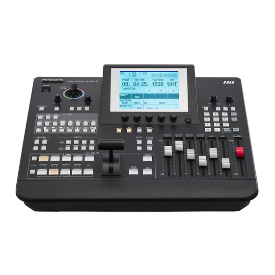
Digital AV Mixer
AG-HMX100P
AG-HMX100E
Vol.1
ENGLISH
VQT2U23
Advertisement
Table of Contents

Related Manuals for Panasonic AG-HMX100E


Summary of Contents for Panasonic AG-HMX100E
-
Page 1: Operating Instructions
AV mixer, refer to Operating Instructions Vol. 2 (pdf file) contained in the supplied CD-ROM. Before operating this product, please read the instructions carefully and save this manual for future use. SS0810RI0 -PS D Printed in Japan AG-HMX100P Model No. AG-HMX100E Model No. Vol.1 Digital AV Mixer ENGLISH VQT2U23... - Page 2 U.S.A. and Canada. Operation at a voltage other than 120 V AC may require the use of a different AC plug. Please contact either a local or foreign Panasonic authorized service center for assistance in selecting an alternate AC plug.
-
Page 3: Important Safety Instructions
Read this first! (For AG-HMX100P) (continued) IMPORTANT SAFETY INSTRUCTIONS 1) Read these instructions. 2) Keep these instructions. 3) Heed all warnings. 4) Follow all instructions. 5) Do not use this apparatus near water. 6) Clean only with dry cloth. 7) Do not block any ventilation openings. Install in accordance with the manufacturer’s instructions. 8) Do not install near any heat sources such as radiators, heat registers, stoves, or other apparatus (including amplifiers) that produce heat. - Page 4 Declaration of Conformity Model Number: AG-HMX100P Trade Name: Panasonic Responsible Party: Panasonic Corporation of North America One Panasonic Way, Secaucus, NJ07094 Support contact: 1-800-524-1448 This device complies with Part 15 of the FCC Rules. Operation is subject to the following two conditions: (1)This device may not cause harmful interference, and (2) this device must accept any interference received, including interference that may cause undesired operation.
- Page 5 Read this first! (For AG-HMX100E) WARNING: This equipment must be earthed. To ensure safe operation, the three-pin plug must be inserted only into a standard three-pin power point which is effectively earthed through normal household wiring. Extension cords used with the equipment must have three cores and be correctly wired to provide connection to the earth.
-
Page 6: Caution For Ac Mains Lead
Read this first! (For AG-HMX100E) (continued) Caution for AC Mains Lead FOR YOUR SAFETY PLEASE READ THE FOLLOWING TEXT CAREFULLY. This product is equipped with 2 types of AC mains cable. One is for continental Europe, etc. and the other one is only for U.K. - Page 7 4. Connect the apparatus to another power outlet where the power is not shared by any other appliances. Pursuant to at the directive 2004/108/EC, article 9(2) Panasonic Testing Centre Panasonic Service Europe, a division of Panasonic Marketing Europe GmbH Winsbergring 15, 22525 Hamburg, F.R. Germany...
-
Page 8: Table Of Contents
Contents Requests on Use ...9 OVERVIEW...10 Features ... 10 AV Mixer Functions ... 11 Accessories ... 12 Components and Functions ... 13 Operation Panel (Front) ... 13 Connector Area (Rear) ... 15 Basic Operation ...16 System Configuration Examples ... 16 SD Video Processing System... -
Page 9: Requests On Use
Requests on Use Do not use this equipment near radio transmitters or high-voltage equipment or do not generate static electricity to this equipment as it may adversely affect the recorded images, sound, operation, LED (indication), and the like. Keep this equipment away from equipment that generates magnetic fields or electromagnetic waves. The powerful magnetic fields generated by speakers or large motors may adversely affect the recorded images and/or sound. -
Page 10: Overview
GPI and RS-232C connectors are equipped to connect an external controller. Projector control Panasonic projector connected can be controlled from this unit to turn on/off the power and shutter (RS-232C control). Frame synchronizer The built-in frame synchronizer can be used for frame alignment of all input sources, requiring no synchronization of input signals. -
Page 11: Av Mixer Functions
AV Mixer Functions The following shows the operation examples for video production with the AV mixer functions. Basic Operation (see “Operation Manual Volume ”) Configuring a system ( page 16) Starting the unit ( page 19) Setup ( page 19) •... -
Page 12: Accessories
Accessories Power cable ×1 for AG-HMX100P, ×2 for AG-HMX100E CD-ROM ×1 NOTE • Be sure to appropriately dispose of the packing material when you have unpacked the product. • Consult your supplier regarding purchase of accessories. -
Page 13: Components And Functions
Components and Functions Operation Panel (Front) POWER X / Y P B / P R ASPECT PROJECTOR/ REMOTE HOLD PATTERN REVERSE EFFECTS CHROMA P in P PREVIEW PROG PROG STILL STROBE PRESET PRESET A / PROG SOURCE SOURCE SOURCE SHIFT 1 / 5 2 / 6 3 / 7... - Page 14 • . (period) key* ( pages 32, Vol.2-21) • SHIFT key ( pages 27, 28, 30, 32, 33, Vol.2-4, Vol.2-9, Vol.2-10, Vol.2-13, Vol.2-15) • (confirm) key* 15 MASTER fader ( page 33) 16 MIC fader ( page 27, 28, 33) 17 AUX fader (...
-
Page 15: Connector Area (Rear)
Connector Area (Rear) For devices and signals which can be connected to each connector, see “System Configuration Examples” ( page 16) and “Example Connections with 3D Camera” ( pages Vol.2-22 to 24). DVI-I IN IN 1 SDI IN VIDEO IN 1 SDI IN 1 to 4 connectors 2 DVI-I IN connector (... -
Page 16: Basic Operation
Basic Operation This chapter describes the initial setup operation for video processing and audio mixing, and the operation of selecting video and audio sources, and setting the basic video switching effects. System Configuration Examples This unit can be connected to video equipment including cameras, P2 devices and VTRs to digitally process video and sound input sources. -
Page 17: Hd Video Processing System
HD Video Processing System Loop- System camera through Professional-use SDI (video and camera audio) input Professional-use camera SDI IN 1 SDI IN 2 SDI IN 3 (video audio) input SDI IN 4 Termi- nation HDMI IN 1 P2 mobile HDMI IN 2 HDMI input HDMI input Home-use video camera... -
Page 18: System With External Controller
System with External Controller For using an external controller, it is necessary to perform the following operations in advance: • Enter this unit to remote mode using the [RS-232C] submenu of the [SETUP] menu ( • Press the PROJECTOR/REMOTE button to turn on to activate RS-232C control. System camera Loop- through... -
Page 19: Power-On
Keep pressing down the POWER button for 3 seconds or more, and the power of this unit is turned off. Initial Setup When you use Panasonic AG-HMX100P/HMX100E for the first time, you need to make the settings as described below with the [SETUP] menu ( page 22) and [INT VIDEO] menu ( page 28) to set up this unit. -
Page 20: Setting Screen
Setting Screen When setting up this unit or adjusting functions, you need to check the current settings on the LCD screen. The following shows the basic configuration of the setting screen. POS. EVENT VIDEO EFFECTS MOSAIC DEFOCUS MONO 1 Joystick, rotary Z control settings, and 3D display area Shows the setting values of the joystick and rotary Z control;... -
Page 21: Basic Operation Of Menus
6 Menu display area Shows the setting items and values of the currently selected menu. The leftmost column has the setting items and the second to fourth columns have the setting values. (The leftmost column shows the setting values when the [COLOR EFFECTS] menu is displayed.) The setting items and values are displayed three lines at a time. -
Page 22: [Setup] Menu (Setup Operation) Screen
Rotary 2 Rotary 3 Rotary 4 Scroll the screen to display. 20dB (AG-HMX100P) or 18dB (AG-HMX100E) Setting the Startup Mode [MODE] The [MODE] submenu of the [SETUP] menu is used to specify how to reproduce the stored settings when this unit is restarted (startup mode). -
Page 23: Changing Direct Patterns [Direct Pattern]
• Position setting values of patterns registered as direct patterns • Button ON/OFF state • Time setting values (transition, DSK, and fade) The factory default setting is [PRESET]. Changing Direct Patterns [DIRECT PATTERN] The patterns that are frequently used for transition and keys are registered as “direct patterns.”... -
Page 24: Setting Video And Audio Input Sources [Audio Video]
Example of DIRECT PATTERN KEY screen POS. X 128 Y 128 Z 196 EVENT ME TIME PATTERN 1:00 3002 WHT DIRECT PATTERN KEY ENTER TO EXIT PATTERN WIDTH COLOR EDGE HARD WHITE EFFECTS EMPTY LEARN SETUP 9000 Up to six key patterns can be stored. It is also possible to change the settings for the edge of each pattern or set and store effects for each pattern (... - Page 25 NOTE The same input sources are assigned to the A/PROG bus and the B/PRESET bus. It is impossible to assign different sources to each bus. You can check the input source currently assigned to the selected number on the monitor connected to the SDI OUT PVW connector.
-
Page 26: Setting The Video Format [Video Format]
When the system format in which the setup level cannot be specified has been selected, [--] appears. The factory default is [7.5] (AG-HMX100P) or [0] (AG-HMX100E). Changing the system format Select the system format that you want to set using the rotary 2 control. -
Page 27: Setting The Bus [Bus]
• When the 3D mode is [OFF] ( page Vol.2-25), the system format of this unit is the one set in the [VIDEO FORMAT] submenu of the [SETUP] menu. When the 3D mode is other than [OFF], the system format of this unit is the one set under the [3DFORMAT] item in the [3D] submenu of the [SETUP] menu. -
Page 28: [Int Video] Menu (Internal Video Setting) Screen
To set the audio output format and the operation of audio faders Set [SOURCE] to [CP PAIR], [BUS SEP1], [BUS SEP2], [12 PAIR], or [12 SEPA.] using the rotary 2 control. The following table shows the output method and audio input sources assigned to the faders for each setting. Setting Output Method SOURCE 1/5 Fader... -
Page 29: Setting The Back Matte [Back Matte]
Use the rotary 1 control to set the internal video output type to back matte video ([BACK MATTE]) or color bar output ([COLOR BAR]). If [MEMORY] is selected, an external video input source can be saved in internal memory and used as internal video (... -
Page 30: Outputting Color Bars [Color Bar]
If other than [CUSTOM1] and [CUSTOM2] is selected in Step 2, [WASH] is automatically selected. Use the joystick and rotary Z control to set the ] and [P ] values in the range of 0 to 255 and the [Y] value in the range of 16 to 235 for selecting the wash color. - Page 31 To save still pictures used as internal video Rotary 1 Rotary 2 Rotary 3 Rotary 4 MEMORY PAGE FRAME FRAME 1-30 (480i) 1-30 (480i) FIELD 1-30 (576i) 1-30 (576i) FRAME 1-14 (720p) 1-14 (720p) 1-6 (1080i) 1-6 (1080i) NOTE The number of pages set under the [INT V] item in the [MEMORY] submenu of the [SETUP] menu is displayed as the [PAGE] setting value and can be set up to the maximum value.
-
Page 32: Using Video Input From Pc [Pc1]
Set [FRAME] to the number of frames to preview using the rotary 3 control. To preview the movie, select a value equivalent to or smaller than the number of frames of the movie. To preview the still picture, select [FRAME] (frame display) or [FIELD] (field display) using the rotary 4 control. -
Page 33: Switching Or Combining Of Video
Switching or Combining of Video Procedures of switching or combining video are described below. Selecting Source Video and Sound This section describes the procedure of selecting source video and sound to be provided with effects or mixed on this unit. To select input sources Allocate video and sound to eight channels of input sources in the [AUDIO VIDEO] submenu... -
Page 34: Ab Transition
NOTE If the AUDIO FOLLOW VIDEO button has been pressed to turn on to interlock the audio faders with the transition lever or the audio level of input source 5 to 8 has been adjusted with the SHIFT key pressed, the audio fader settings may not match the actual audio level. -
Page 35: Program Preset Transition
To select a pattern The currently selected pattern number is shown in the event number, transition, pattern number, and internal video display area of the setting screen ( page 20). PATTERN 0001 Press the PATTERN button to turn on. Set the pattern number by entering a numeric value with the numeric keys or using the + and −... -
Page 36: Downstream Key (Dsk)
For luminance keying, chroma keying or external keying, apply effects such as slice and slope to the key video ( page Vol.2-6). Set the pattern position (where the key is inserted) using the joystick. Press the CENTER button to turn on, and the pattern position is set to the center. - Page 37 The following figure shows an example connection of source equipment, PC, and this unit. Professional-use P2 mobile camera SDI (video and audio) input SDI IN 3 SDI IN 4 AG-HMX100P/HMX100E DVI-I IN DVI-I input HMX100 To execute DSK DSK is executed with the DSK execution button. Confirm that the DSK execution button is off.
-
Page 38: Fade
Fade Fade is an effect of gradually erasing images or decreasing the sound level (fade-out) or gradually displaying images or increasing the sound level (fade-in). The following diagram shows an example of fade-out. Fade is executed with the FADE execution button. Set the fading method in the [FADE] submenu of the [DSK FADE] menu (... -
Page 39: Before Calling For Service
Before Calling for Service Troubleshooting Contact your dealer if the problem persists even when you have checked the following items. AG-HMX100P/HMX100E-related problems Problem What to Check • The power cannot be switched on. Is the plug of the power cable inserted properly in the outlet? •... -
Page 40: Specifications
Specifications Power source: Power consumption: Indicates safety information. [General] Operating temperature: 5 °C to 40 °C (41 °F to 104 °F) Operating humidity: Between 10 % and 80 % (no condensation) Storage temperature: –20 °C to 60 °C (–4 °F to 122 °F) Storage humidity: Between 10 % and 80 % (no condensation) Dimensions:... - Page 41 [VIDEO INPUT/OUTPUT] BNC x 2 sets, 1.0 V[p-p], 75 Ω termination Analog composite input (VIDEO IN): SDI input: BNC x 4 sets SD serial digital signal: Complying with SMPTE259M-C/272M-A and ITU-R BT.656-4 standards HD serial digital signal: Complying with SMPTE292M/296M/299M standards HDMI input: HDMI connector x 2 sets (Type A connector), incompatible with HDCP DVI-I input:...
-
Page 42: Signal Format Supported On The Unit
[OTHER] TALLY output : D-sub 9-pin, 8 cross points, open-collector Maximum current: 50 mA or less Maximum voltage: 35 V DC GPI input: BNC x 1, make-contact RS-232C : D-sub 9-pin Signal Format Supported on the Unit Format VIDEO NTSC 480/59.94i 480/59.94p 576/50i... -
Page 43: Signal Format Supported On The Unit In 3D Mode
Signal Format Supported on the Unit in 3D Mode Format VIDEO NTSC 480/59.94i 480/59.94p 576/50i 576/50p 720/50p 720/59.94p 1035/59.94i * 1080/23.98PsF 1080/23.98p over 59.94i 1080/25PsF 1080/25p over 50i 1080/29.97PsF 1080/29.97p over 59.94i 1080/50i 1080/59.94i Treated as 1080/59.94i Inrush current, measured according to European standard EN55103-1: 15 A HDMI —... -
Page 44: Index
Index Symbols key ... 14 + key ... 13, 35, 20 − key ... 13, 35, 20 . (period) key ... 14, 32, 21 Numbers [3D] ... 25 3D camera outputs ... 22, 23 As SIDE BY SIDE signal ... 23 For simultaneous display of L/R channels ... - Page 45 EFFECTS buttons for A/PROG and B/PRESET buses ... 14, 13, 15 COLOR EFFECTS buttons ... 14 STILL buttons ... 14 STROBE buttons ... 14 VIDEO EFFECTS buttons ... 14 Effects to video, applying ... 13 Environment settings ... 26 [EQ] ... 17 [EQ MID] ...
- Page 46 ONE WAY button ... 14, 34 [PAINT] ... 16 Paint effect ... 16 [PAN] ... 17 Pan setting ... 17 PATTERN area ... 14, 23, 34, 35, 6, 7 PATTERN button ... 13, 35 Pattern edge ... 4 [PATTERN EDGE] ... 4, 5 Pattern key ...
- Page 47 MEMO...
- Page 48 Panasonic Corporation Web Site: http://panasonic.net Panasonic Solutions Company 3 Panasonic Way, Secaucus, NJ 07094 Tel: 877-803-8492 www.panasonic.com/broadcast e-mail: MediaProServices.PSC@us.panasonic.com Panasonic Canada Inc. 5770 Ambler Drive, Mississauga, Ontario L4W 2T3 Tel: 905-624-5010 Panasonic de México S.A. De C.V.