Table of Contents
Advertisement
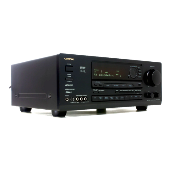
Audio Video Control Receiver
TX-DS656
Instruction Manual
SYSTEM
STAND-BY
POWER
ON
OFF
SPEAKERS
MAIN
REMOTE
REC OUT
MULTI SOURCE
DIGITAL AUDIO
SELECTOR
MUL
TI CH INPUT
PHONES
VIDEO
/ 3
VIDEO CAM INPUT
DVD
VIDEO-1
VIDEO-2
VIDEO-3
VCR-1
VCR-2 / TV
CAM
S VIDEO
VIDEO
L
AUDIO
R(MONO)
Thank you
for purchasing the Onkyo Audio Video
Control Receiver.
Please read this manual thoroughly before making
connections and turning on the power.
Following the instructions in this manual will enable
you to obtain optimum performance and listening
enjoyment from your new Audio Video Control
Receiver.
Please retain this manual for future reference.
MASTER VOLUME
SMART SCAN CONTROLLER
PRESET
TUNING
SURROUND
ENTER
PARAMETER
3-D BASS
MIDNIGHT
Re-EQ
THEATER
MIN
MAX
PTY/TP
DISPLAY
CHARACTER
AUTO TUN
SCAN
GROUP
MEMORY FM MUTE / MODE
BASS
TREBLE
CLEAR
TAPE-2
FM
AM
PHONO
CD
TAPE-1
M D
MONITOR
TX-DS
AUDIO VIDEO CONTROL RECEIVER
Before using
Important Safeguards ........................... 2
Precautions ........................................... 3
Features ................................................ 4
Supplied accessories ............................ 4
Before using this unit ........................... 5
Preparation
Connection ........................................... 6
On-screen setting ............................... 18
Speaker system setup ......................... 21
Listening to FM/AM broadcasts ........ 32
Using the Surround modes ................. 38
Recording from a source .................... 42
656
Multi-room system connections......... 46
A few important notes
Troubleshooting ................................. 50
Specifications ..................................... 52
Control positions and names .............. 53
Contents
setup ................................................. 25
(European models only) ................... 36
function ............................................ 44
with the supplied remote controller ..... 45
Advertisement
Table of Contents

Related Manuals for Onkyo TX-DS656


Summary of Contents for Onkyo TX-DS656
-
Page 1: Table Of Contents
S VIDEO VIDEO AUDIO R(MONO) Thank you for purchasing the Onkyo Audio Video Control Receiver. Please read this manual thoroughly before making connections and turning on the power. Following the instructions in this manual will enable you to obtain optimum performance and listening enjoyment from your new Audio Video Control Receiver. -
Page 2: Important Safeguards
WARNING TO REDUCE THE RISK OF FIRE OR ELECTRIC SHOCK, DO NOT EXPOSE THIS APPLIANCE TO RAIN OR MOISTURE. CAUTION TO REDUCE THE RISK OF ELECTRIC SHOCK, DO NOT REMOVE COVER (OR BACK). NO USER- SERVICEABLE PARTS INSIDE. REFER SERVICING TO QUALIFIED SERVICE PERSONNEL. -
Page 3: Precautions
3. AC Fuse The fuse is located inside the chassis and is not user-serviceable. If power does not come on, contact your Onkyo authorized service station. 4. Care From time to time you should wipe off the front and rear panels and the cabinet with a soft cloth. -
Page 4: Features
Multi-Room Remote System (MRX) By connecting the Multi-Room Remote System equipment, you can operate all components connected to the TX-DS656 from either the main room or the sub-room. (Refer to pages 46 to 48 for more details.) The following equipment (sold separately) is essential for using the Onkyo Multi-Room System: U.S. -
Page 5: Before Using This Unit
Before using this unit AM FREQUENCY STEP 10kHz 9kHz 27122482 TX-DS656 STAND-BY indicator 30˚ 30˚ RC-373M Setting the AM tuning step frequency (worldwide model only) Worldwide models are equipped with a switch that controls the AM band tuning steps. Set this switch to match the AM band tuning step frequency in your area. -
Page 6: Connection
Connection This section describes, step by step, how to connect the TX-DS656 to your home theater components. 1 Connecting analog audio source equipment 2 Connecting digital audio source equipment 3 Connecting video source equipment 4 Connecting a video camera or TV game machine 5 Connecting a decoder with 5.1-channel output... - Page 7 3 Connecting video source equipment 6 Connecting video recording equipment Video cassette recorder 3 Connecting video source equipment DVD player FRONT VIDEO-1 ANTENNA SURROUND MULTI CHANNEL INPUT VIDEO-2 CENTER SUBWOOFER DIGITAL INPUT DIGITAL 1 (OPTICAL) MONITOR DIGITAL 2 (REC) OUTPUT (COAXIAL) TAPE-1 DIGITAL 3...
-
Page 8: Connecting Analog/Digital Audio Source Equipment
2 Connecting digital audio source equipment The TX-DS656 has three digital input terminals. Therefore, you can connect up to three digital audio sources, such as a CD player, MD recorder, or DAT deck, etc., using optical and coaxial cables. - Page 9 REMOTE CONTROL SWITCHED TOTAL 120W 1A MAX. WARNING AVIS • Video input signals to the TX-DS656 cannot be output back to the same or RISK OF ELECTRIC SHOCK DO NOT OPEN RISQUE DE CHOC ELECTRIQUE NE PAS OUVRIR other equipment. In other words, the VIDEO-1 V OUT jack does not output signals which have been input to the TX-DS656 from its VIDEO-1 V IN jack.
- Page 10 CENTER SURROUND SPEAKERS FRONT MAIN SPEAKERS SPEAKER The TX-DS656's MULTI CHANNEL INPUT jacks can be used to CAUTION: SPEAKER IMPEDANCE 6 OHMS MIN. / SPEAKER connect a decoder equipped with 5.1-ch audio output (dts decoder, FRONT REMOTE SPEAKERS AC OUTLETS...
- Page 11 TOTAL 120W 1A MAX. WARNING AVIS (PLAY) RISK OF ELECTRIC SHOCK RISQUE DE CHOC ELECTRIQUE an z jack can be connected to the TX-DS656 via the remote control PHONO TAPE-2 CENTER SUBWOOFER PRE OUT DO NOT OPEN NE PAS OUVRIR cable supplied with the unit.
- Page 12 RISQUE DE CHOC ELECTRIQUE DO NOT OPEN NE PAS OUVRIR PRE OUT "." flashes on the display and the TX-DS656 automatically turns off in about 5 minutes. To activate the IPM function... 1. Connect the audio output of your TV to the TX-DS656's VIDEO-2 L and R IN jacks.
- Page 13 Connection Outdoor antenna Slit C Directional linkage- type splitter To TX-DS656 Insert into the hole. 0 Connecting the antennas Indoor antenna Connecting the antenna cable to the 75/300 ohm 300 ohms antenna adapter (worldwide models) ribbon wire Connecting a 300 ohm ribbon wire to the 75/300 ohm adapter: Loosen the screws and wrap the wire around them.
- Page 14 Connection U.S. and Canadian models Other models ANTENNA U.S. and Canadian models Other models ANTENNA ANTENNA U.S. and Canadian models Other models ANTENNA U.S. and Canadian models Other models ANTENNA ANTENNA Connecting the included antennas Connecting the T-shaped FM antenna: ANTENNA The T-shaped FM antenna is for indoor use only.
-
Page 15: Connecting Speakers
(Left Surround) 15mm A Connecting speakers On the rear panel of the TX-DS656, two sets of speaker terminals are provided; one for main-room speakers and the other for sub-room speakers. This section provides information on connecting the main- room speakers. -
Page 16: Connecting Power Amplifiers
MULTI CHANNEL INPUT VIDEO-2 CENTER SUBWOOFER CAUTION: SPEAKER IMPEDANCE 6 OHMS MIN. / SPEAKER DIGITAL INPUT than with the TX-DS656 alone. If power amplifiers are used, connect DIGITAL 1 (OPTICAL) MONITOR DIGITAL 2 OUTPUT (COAXIAL) FRONT REMOTE SPEAKERS TAPE-1 FRONT... -
Page 17: Connecting The Power
C Using the AC outlets You can connect the power cord from other audio device to the rear of the TX-DS656. Since the AC outlets on the unit are the SWITCHED type, you can use the POWER button (or the SYSTEM button), or the POWER button on the remote controller to turn on/off the power to both the TX-DS656 and the connected audio devices. -
Page 18: On-Screen Setting
On-screen setting If your TX-DS656 is connected to a TV set, you can perform various settings on the TV screen. This section shows you the basic operation of on- screen setting, as well as the method of changing the screen setup according to your preference. - Page 19 On-screen setting *** Menu *** Input Selector Rec Selector ENTER Surround Setup Screen Setup System Setup *** Menu *** Input Selector Rec Selector Surround Setup ENTER Screen Setup System Setup ** Screen Setup ** Background Color = BLUE-1 Superimpose ENTER Mode = NORMAL Immediate Display = ON...
- Page 20 Select ON or OFF. When ON, information such as the video and audio equipment currently selected appears on the TV screen for 3 seconds each time you operate your TX-DS656. Character Position You can move the on-screen display to the lower left, upper left, upper right or lower right corner of the TV screen.
-
Page 21: Speaker System Setup
Speaker system setup • Before performing speaker system setup, make sure that the speakers have been connected properly. • To get optimized surround effects, you need the correct speaker setting for your speaker system and listening environment. What is "System Setup"? In Speaker Setup, you perform the following three operations. - Page 22 Speaker system setup *** Menu *** Input Selector Rec Selector Surround Setup Screen Setup System Setup ** System Setup ** Speaker Setup Speaker Distance Level Calibration Starting the Test Signal. * Speaker Setup * Subwoofer = Front = LARGE Center = SMALL Surround = SMALL...
- Page 23 Speaker system setup POWER (or SYSTEM) button SMART SCAN CONTROLLER jog dial SYSTEM ENTER STAND-BY POWER SPEAKERS MAIN REMOTE MIDNIGHT REC OUT MULTI SOURCE Re-EQ THEATER DIGITAL AUDIO SELECTOR TI CH INPUT PTY/ TP DISPLAY CHARACTER AUTO TUN PHONES VIDEO VIDEO CAM INPUT VIDEO-1 VIDEO-2...
- Page 24 Speaker system setup SUBROOM SENDING/ LEARNED LEARN TEST POWER SLEEP DIMMER TONE MODE POWER button SOURCE SELECTOR TI-CH VIDEO-1 VIDEO-2 VIDEO-3 INPUT TAPE-1 TAPE-2 TUNER PHONO PROGRAMMABLE AREA TV VIDEO POWER VOLUME POWER TV/ VCR TUNER GROUP PRESET TAPE DISC SUBTITLE ON / OFF PAUSE...
-
Page 25: Input Source Selection And Surround Setup
RC-373M REMOTE CONTROLLER Using the on-screen Menu If your TX-DS656 is connected to a TV set, you can perform settings on the TV screen. For further information about using the on-screen Menu, see "Selecting a Menu item" on page 19. - Page 26 "Using the TAPE-2 MONITOR function" on page 44. If the selected input source is connected to one of the DIGITAL INPUT connectors of the TX-DS656... Select "Input Mode" using the y or u cursor button and then press the s button to display the Digital Selector screen.
- Page 27 Turntable CD player If the selected input source is connected to one of the DIGITAL INPUT connectors of the TX-DS656... Press the DIGITAL AUDIO SELECTOR button. Rotate the SMART SCAN CONTROLLER to select the DIGITAL INPUT connector to which the input source is connected, then press the ENTER button.
- Page 28 Cassette tape deck TUNER Built-in tuner PHONO Turntable CD player If the selected input source is connected to one of the DIGITAL INPUT connectors of the TX-DS656... For details, "Selecting the digital/analog audio input" on page 30. SUBROOM SENDING/ LEARN LEARNED TEST...
- Page 29 Input source selection and surround setup SYSTEM ENTER STAND-BY POWER SPEAKERS MAIN REMOTE MIDNIGHT REC OUT MULTI SOURCE Re-EQ THEATER DIGITAL AUDIO SELECTOR TI CH INPUT PTY/ TP DISPLAY CHARACTER AUTO TUN PHONES VIDEO VIDEO CAM INPUT VIDEO-1 VIDEO-2 VIDEO-3 TAPE-1 TAPE -2 VCR-1...
- Page 30 • Pressing the DIGITAL AUDIO SELECTOR button to select a digital audio input channel when no digital audio input source is connected may cause the DOLBY DIGITAL indicator to appear on the display. This occurs when the TX-DS656's built-in microprocessor cannot set the correct surround mode after investigating the connected digital input source and is not a failure.
- Page 31 • The Muting function will be canceled automatically if the unit's power switch is turned off. Falling asleep with music (Sleep function) You can turn off the power supplied to the TX-DS656 automatically at a specified time. SLEEP Press the SLEEP button.
-
Page 32: Listening To Fm/Am Broadcasts
Tuning in a broadcasting station You can use one of the following two methods to listen to FM/AM broadcasts with the TX-DS656's built-in tuner. • Tune in a broadcasting station - Tune in an FM/AM station by specifying the frequency (Manual... - Page 33 Listening to FM/AM broadcasts Recalling a preset broadcasting station If you preset favorite broadcasting stations, you will be able to select them by using the on-screen Menu and/or the remote controller. You can preset a total of 30 FM and AM stations in three groups. Each of the groups (A, B, and C) can store up to 10 stations. SYSTEM STAND-BY POWER...
- Page 34 Listening to FM/AM broadcasts SENDING/ SUBROOM LEARNED LEARN TEST POWER SLEEP DIMMER TONE MODE SOURCE SELECTOR TI-CH VIDEO-1 VIDEO-2 VIDEO-3 INPUT TAPE-1 TAPE-2 TUNER PHONO PROGRAMMABLE AREA TV VIDEO POWER VOLUME POWER TV/ VCR TUNER GROUP PRESET TAPE DISC SUBTITLE ON / OFF PAUSE / STEP...
- Page 35 Listening to FM/AM broadcasts Entering a station name Characters which can be entered: A B C D E F G H I J K L M N O P Q R S T U V W X Y Z " & , ( ) * + , - . / = ? [ ] | 0 1 2 3 4 5 6 7 8 9 Note: indicates a space.
-
Page 36: Receiving Rds Broadcasts (European Models Only)
NOTE: In some cases, the characters displayed on the TX-DS656's display may not be exactly the same as the ones broadcast by the radio station. Unusual characters may appear on the display if the TX-DS656 receives characters that cannot be displayed correctly. - Page 37 Receiving RDS broadcasts (European models only) SYSTEM STAND-BY POWER PHONES VIDEO S VIDEO VIDEO PTY/TP SMART SCAN CONTROLLER SCAN PTY/TP PTY/TP DISPLAY Entered Character or Frequency Program Service Name Radio Text SMART SCAN CONTROLLER jog dial TUNING button SMART SCAN CONTROLLER PRESET TUNING SURROUND...
-
Page 38: Using The Surround Modes
Using the Surround modes The TX-DS656 provides a variety of surround effects, enabling you to enjoy the feeling of a movie theater, concert hall or studio in your room. To get optimized surround sounds, your speaker system plays an important role. For how to connect and setup speakers, see "Connecting speakers"... - Page 39 Using the Surround modes *** Menu *** Input Selector Rec Selector Surround Setup Screen Setup System Setup ** Surround Setup ** Surround Mode= HALL Hall Size = LARGE Effect Level = 1.0 Reverb Level = 1.0 SUBROOM SENDING/ LEARNED LEARN POWER SLEEP DIMMER...
- Page 40 Using the Surround modes Changing the surround mode parameters Each surround mode is made up of a number of parameters. These parameters can be changed to optimize the reproduced surround sound according to your room size, listening environment, playback source type, taste, etc. Once parameters are set, they will be recalled automatically every time the same surround mode is selected. The parameters available in each surround mode vary depending on the surround mode.
- Page 41 Using the Surround modes SMART SCAN CONTROLLER jog dial SMART SCAN CONTROLLER SYSTEM ENTER STAND-BY POWER SPEAKERS MAIN REMOTE MIDNIGHT REC OUT MULTI SOURCE Re-EQ THEATER DIGITAL AUDIO TI CH INPUT SELECTOR PTY/TP DISPLAY CHARACTER AUTO TUN SCAN PHONES VIDEO VIDEO CAM INPUT VIDEO-1 VIDEO-2...
-
Page 42: Recording From A Source
Monitor function). *3 The TX-DS656 will not output S-video signals if its S-video IN connector is not connected to the S-video output of the source equipment, even if its S-video OUT connector is connected to the S-video input of the source. - Page 43 Recording from a source Display ENTER SMART SCAN CONTROLLER SYSTEM ENTER STAND-BY POWER SPEAKERS MAIN REMOTE MIDNIGHT REC OUT MULTI SOURCE Re-EQ THEATER DIGITAL AUDIO SELECTOR TI CH INPUT PTY/TP DISPLAY CHARACTER AUTO TUN SCAN PHONES VIDEO VIDEO CAM INPUT VIDEO-1 VIDEO-2 VIDEO-3...
-
Page 44: Using The Tape-2 Monitor Function
Using the front panel 1. Follow the procedure described in "Recording from an audio/ video source" on page 43. Record with a 3-head cassette tape deck connected to the TAPE-2 jacks of the TX-DS656. MASTER VOLUME PRESET TUNING 2. Press the TAPE-2 MONITOR button on the front panel. -
Page 45: Using The Other Remote Controller Functions With The Supplied Remote Controller
POWER The remote controller supplied with the TX-DS656 can learn functions available with other compo- nent's remote controllers. The control codes for Onkyo cassette tape decks and CD players are already available with the supplied remote controller. A/B-SUBROOM/ SENDING/LEARNED indicator... -
Page 46: Multi-Room System Connections
1. Onkyo components (a) TX-DS656 Main Main speaker speaker Power supply B. Using a remote controller to operate components not displaying Onkyo's z mark from the sub-room MAIN ROOM 3. Emitter 4. Components(d) TX-DS656 1. Components(b) Main speaker Main... - Page 47 MAIN ROOM 1. Onkyo components (a) TX-DS656 Main Main speaker speaker B. Using a remote controller to operate components not displaying Onkyo's z mark from the sub-room 3. Remote Emitter MAIN ROOM HE-50(AC) 5. Remote Emitter Head HE-10 Power supply 4.
- Page 48 Multi-room system connections SPEAKERS REMOTE SYSTEM STAND-BY POWER SPEAKERS MAIN REMOTE REC OUT MULTI SOURCE Re-EQ DIGITAL AUDIO TI CH INPUT SELECTOR PTY/ TP DISPLAY CHARACTER AUTO TUN PHONES VIDEO VIDEO CAM INPUT VIDEO-1 VIDEO-2 VIDEO-3 TAPE-2 TAPE-1 VCR-1 VCR-2 / TV MONITOR S VIDEO VIDEO...
- Page 49 Memo...
-
Page 50: Troubleshooting
• Remove the AC plug from the outlet, leave the unit for 5 seconds or more, and then plug it again. • Contact your Onkyo service center. • Press the TAPE-2 MONITOR button to turn it off. • Turn it off using the remote controller MUTING button. - Page 51 Troubleshooting Trouble AM stations cannot be received. Buzzing noise on AM (particularly conspicuous at night or with weak stations) High-pitched noise or buzzing noise on AM Crackling noise on AM or FM FM TUNED and STEREO indicators light but sound is distorted and stereo separation is bad. FM TUNED and STEREO indicators flicker and a hiss is heard on FM.
-
Page 52: Specifications
Specifications AMPLIFIER SECTION Continuous Average Power output (FTC) Front Main L/R channels: 85 watts per channel min. RMS at 8 ohms, both channels driven from 20Hz to 20kHz with no more than 0.08% total harmonic distortion. Center channel: 85 watts min. RMS at 8 ohms, driven from 20Hz to 20kHz with no more than 0.08% total harmonic distortion. -
Page 53: Control Positions And Names
Control positions and names Rear panel VIDEO-1 ANTENNA VIDEO-2 (REC) TAPE-1 (PLAY) (REC) (PLAY) PHONO TAPE-2 US and Canadian models Rear panel For more information about buttons or controls, refer to the pages listed in brackets ( [ ] ) below. 1. - Page 54 Control positions and names Front panel SYSTEM STAND-BY POWER PHONES VIDEO VIDEO CAM INPUT S VIDEO VIDEO AUDIO R(MONO) European models Front panel For more information about buttons or controls, refer to the pages listed in brackets ([ ]) below. 1.
- Page 55 5. SOURCE SELECTOR buttons [28, 34, 48] 6. PROGRAMMABLE AREA TV/VIDEO buttons [45] 7. CD player operation buttons These buttons are used to operate an ONKYO CD player that bears the z terminal. (Refer to page 11 for z connection.) 8. DVD player operation buttons These buttons are used to operate an ONKYO DVD player that bears the z terminal.
- Page 56 Tel: 201-825-7950 Fax: 201-825-8150 E-mail: onkyo@onkyousa.com ONKYO EUROPE ELECTRONICS GmbH Industriestrasse 20, 82110 Germering, GERMANY Tel: 089 84 93 20 Fax: 089 84 93 226 E-mail: info@onkyo.de ONKYO EUROPE FRANCE BRANCH Domaine Technologique de Saclay 4, Rue René Razel, SACLAY-91892...