Hitachi L100 Instruction Manual
L100 series
Hide thumbs
Also See for L100:
- Instruction manual (193 pages) ,
- Service manual (69 pages) ,
- Quick reference manual (25 pages)
Table of Contents
Advertisement
HITACHI
L100 Series Inverter
Instruction Manual
• Single-phase Input 200V Class
• Three-phase Input 200V Class
• Three-phase Input 400V Class
Toll Free: voice: 1-877-539-2542 fax: 1-800-539-2542 www.mgitech.com
Technologies Inc.
Manual Number: NB576XA
After reading this manual,
keep it handy for future reference.
Hitachi, Ltd.
Tokyo Japan
Advertisement
Table of Contents
Troubleshooting

Related Manuals for Hitachi L100


Summary of Contents for Hitachi L100
- Page 1 HITACHI L100 Series Inverter Instruction Manual • Single-phase Input 200V Class • Three-phase Input 200V Class • Three-phase Input 400V Class Toll Free: voice: 1-877-539-2542 fax: 1-800-539-2542 www.mgitech.com Technologies Inc. Manual Number: NB576XA After reading this manual, keep it handy for future reference.
-
Page 2: Table Of Contents
Index to Warnings and Cautions in This Manual ... vii General Warnings and Cautions ... xii Revisions ... xvii Chapter 1: Getting Started Introduction ...1–2 L100 Inverter Specifications ...1–4 Introduction to Variable-Frequency Drives ...1–7 Frequently Asked Questions ...1–12 Chapter 2: Inverter Mounting and Installation Orientation to Inverter Features ...2–2 Basic System Description ...2–5... - Page 3 Table of Contents Chapter 5: Motor Control Accessories Introduction ... 5–2 Component Descriptions ... 5–3 Chapter 6: Troubleshooting and Maintenance Troubleshooting ... 6–2 Monitoring Trip Events, History, & Conditions ... 6–5 Restoring Factory Default Settings ... 6–8 Maintenance and Inspection ... 6–9 Warranty ...
-
Page 4: Safety Messages
Safety Messages For the best results with the L100 Series inverter, carefully read this manual and all of the warning labels attached to the inverter before installing and operating it, and follow the instructions exactly. Keep this manual handy for quick reference. -
Page 5: General Precautions - Read These First
Hitachi, Ltd. CAUTION: Be sure to connect a motor thermal cutoff switch or overload device to the L100 series controller to assure that the inverter will shut down in the event of an overload or an overheated motor. - Page 6 L100 Inverter be performed only by qualified personnel. Factory-recommended test procedures included in the instruction manual should be followed. Always disconnect electrical power before working on the unit. CAUTION: a) Class I motor must be connected to protective earth via low resistive path (< 0.1ohm) b) Any motor used must be of a suitable rating.
-
Page 7: Precautions For Emc (Electromagnetic Compatibility)
Precautions for EMC (Electromagnetic Compatibility) Precautions for EMC (Electromagnetic Compatibility) You are required to satisfy the EMC directive (89/336/EEC) when using an L100 inverter in a European country. To satisfy the EMC directive and to comply with standard, follow the checklist below. -
Page 8: Index To Warnings And Cautions In This Manual
WARNING: “Suitable for use on a circuit capable of delivering not more than 5,000 rms symmetrical amperes, 240 V maximum.” For models with suffix N or L. Toll Free: voice: 1-877-539-2542 fax: 1-800-539-2542 www.mgitech.com Technologies Inc. L100 Inverter ... 2–6 ... 2–6 ... 2–6 ... 2–6 ... - Page 9 CAUTION: Be sure not to input a single phase to a three-phase- only type inverter. Otherwise, there is the danger of fire. CAUTION: Be sure not to connect an AC power supply to the output terminals. Otherwise, there is the danger of injury and/or fire.
- Page 10 CAUTION: Be sure to install a fuse in the wire for each phase of the main power supply to the inverter. Otherwise, there is the danger of fire. CAUTION: For motor leads, earth leakage breakers and electro- magnetic contactors, be sure to size these components properly (each must have the capacity for rated current and voltage).
- Page 11 Otherwise, it may cause injury to personnel. WARNING: If the power supply is cut off for a short period of time, the inverter may restart operation after the power supply recovers if the command to operate is active.
- Page 12 Warnings and Cautions for Troubleshooting and Maintenance WARNING: Wait at least five (5) minutes after turning off the input power supply before performing maintenance or an inspection. Otherwise, there is the danger of electric shock. WARNING: Make sure that only qualified personnel will perform maintenance, inspection, and part replacement.
-
Page 13: General Warnings And Cautions
(Mgo) on the power supply side, so that the circuit does not allow automatic restarting after the power supply recovers. If the optional remote operator is used and the retry function has been selected, this will also cause automatic restarting when an operation instruction is active. - Page 14 EMI filter on the primary side of inverter. Toll Free: voice: 1-877-539-2542 fax: 1-800-539-2542 www.mgitech.com Technologies Inc. Earth leakage breaker L1, L2, L3 Inverter GND lug L100 Inverter Surge absorber U, V, W Motor Leading power factor capacitor...
- Page 15 1. The unbalance factor of the power supply is 3% or higher. 2. The power supply capacity is at least 10 times greater than the inverter capacity (and the power supply capacity, 500 kVA or more).
-
Page 16: Revisions
%torque, corrected product weight (lbs) Page 2-8 – Corrected H dimension for -002 models Toll Free: voice: 1-877-539-2542 fax: 1-800-539-2542 www.mgitech.com Technologies Inc. Revision History Table Revision Comments xvii L100 Inverter Operation Date of Issue Manual No. May 1999 NB576X August 1999... - Page 17 Toll Free: voice: 1-877-539-2542 fax: 1-800-539-2542 www.mgitech.com Technologies Inc.
- Page 18 Getting Started In This Chapter... — Introduction ... 2 — L100 Inverter Specifications... 4 — Introduction to Variable-Frequency Drives ... 7 — Frequently Asked Questions ... 12 Toll Free: voice: 1-877-539-2542 fax: 1-800-539-2542 www.mgitech.com Technologies Inc. page...
-
Page 19: Introduction
• Continuous torque operation at 100% within a 1:10 speed range (6/60 Hz / 5/50 Hz) without motor derating A full line of accessories from Hitachi is available to complete your application: • Digital remote operator keypad • Dynamic braking unit •... - Page 20 Inverter Specifications Label The Hitachi L100 inverters have product labels located on the right side of the housing, as pictured below. Be sure to verify that the specifications on the labels match your power source, motor, and application safety requirements.
-
Page 21: L100 Inverter Specifications
L100 Inverter Specifications Model-specific tables for 200V and 400V class inverters The following three tables are specific to L100 inverters for the 200V and 400V class model groups. The table on page 1–6 gives the general specifications that apply to both voltage class groups. - Page 22 Footnotes for the preceding tables and the table on the following page: *1: The protection method conforms to JEM 1030. *2: The applicable motor refers to Hitachi standard 3-phase motor (4-pole). To use other motors, care must be taken to prevent the rated motor current (50/60 Hz) from exceeding the rated output current of the inverter.
-
Page 23: General Specifications
1–6 L100 Inverter Specifications General Specifications The following table applies to all L100 inverters. Item Protective housing *1 Control method Output frequency range *4 Frequency accuracy Frequency setting resolution Volt./Freq. characteristic Overload current rating Acceleration/deceleration time Input Freq. Operator panel... -
Page 24: Introduction To Variable-Frequency Drives
Introduction to Variable-Frequency Drives The Purpose of Motor Speed Control for Industry Hitachi inverters provide speed control for 3-phase AC induction motors. You connect AC power to the inverter, and connect the inverter to the motor. You’re probably familiar with the way a light dimmer works to vary the power sent to a light bulb, and thus the light intensity. - Page 25 Speed regulation is a measure of the accuracy speed control, given as a percent difference from a fixed value. The L100 delivers speed regulation (no load to full load) within 3% of the (full scale) motor nameplate speed value.
- Page 26 The Hitachi inverter is a rugged and reliable device. The intention is for the inverter to assume the role of switching power to the motor during all normal operations. Therefore, this manual instructs you not to switch off power to the inverter while the motor is running (unless it is an emergency stop).
- Page 27 See pages 5–2 and 5–5 for more information on the BRD–E2 and BRD–EZ2 braking units. The L100 inverter sends excess motor energy into the resistor in the dynamic braking unit to slow the motor and load. If you have a load that tries to drive the motor continuously for some period of time, that will require a different type of inverter with continuous regenerative capability.
- Page 28 FWD and REV commands determine the direction before the motion starts. NOTE: The L100 can move loads in both directions. However, it is not designed for use in servo-type applications that use a bipolar velocity signal which determines direction. Toll Free: voice: 1-877-539-2542 fax: 1-800-539-2542 www.mgitech.com Technologies Inc.
-
Page 29: Frequently Asked Questions
The term “inverter” is a little confusing, since we also use “drive” and “amplifier” to describe the electronic unit that controls a motor. What does “inverter” mean? Although the L100 inverter is a variable speed drive, can I use it in a fixed-speed application? - Page 30 Why does the manual or other documentation use terminology such as “200V class” instead of naming the actual voltage, such as “230 VAC?” Why is there not a 100V class version of the L100 inverter, so it would work with a USA 115VAC power source, for example? I live in a country where the domestic utility power is 115 VAC.
- Page 31 What type of motor is compatible with the Hitachi inverters? How many poles should the motor have? Will I be able to add dynamic (resistive) braking to my Hitachi L100 drive after the initial installation? How will I know if my application will require resistive braking? Several options related to electrical noise suppression are available for the Hitachi inverters.
- Page 32 Inverter Mounting and Installation In This Chapter... — Orientation to Inverter Features ... 2 — Basic System Description ... 5 — Step-by-Step Basic Installation ... 6 — Powerup Test ... 17 — Using the Front Panel Keypad ... 19 Toll Free: voice: 1-877-539-2542 fax: 1-800-539-2542 www.mgitech.com Technologies Inc.
-
Page 33: Orientation To Inverter Features
Orientation to Inverter Features Unpacking and Inspection Please take a few moments to unpack your new L100 inverter and perform these steps: 1. Look for any damage that may have occurred during shipping. 2. Verify the contents of the box include: a. - Page 34 2–3 L100 Inverter 2. Second-level access - Locate the lift tab at the right lower corner of the front panel near the safety warning message. Lift the corner to swing the half-door around to the left. This exposes four more control buttons and some connectors.
- Page 35 2–4 Orientation to Inverter Features 3. Third-level access - First, ensure no power source of any kind is connected to the inverter. If power has been connected, wait five minutes after powerdown and verify the Power LED is off to proceed. Then locate the recessed retention screw on the left side main front panel (it is along the left hinge area on some models, or behind...
-
Page 36: Basic System Description
AC reactor LCR filter Note that some components are required for regulatory agency compliance (see Chapter 5). 2–5 L100 Inverter Function Current overload protection for power supply and wiring. This is useful in suppressing harmonics induced on the power supply lines, or when... -
Page 37: Step-By-Step Basic Installation
2–6 Step-by-Step Basic Installation Step-by-Step Basic Installation This section will guide you through the following basic steps of installation: 1. Study the warnings associated with mounting the inverter. 2. Select a suitable mounting location. 3. Place covers over the inverter’s ventilation openings to prevent debris from entering. 4. - Page 38 4. Do not open the main front panel door at any time during operation. Toll Free: voice: 1-877-539-2542 fax: 1-800-539-2542 www.mgitech.com Technologies Inc. Clear area 10 cm (3.94”) minimum 12 cm (4.72”) L100 minimum 10 cm (3.94”) minimum Ventilation holes L100 Inverter Air flow (both sides) 2–7...
- Page 39 Inverter Dimensions for Mounting Step 4: Locate the applicable drawing on the following pages for your inverter. Dimensions are given in millimeters (inches) format. External Dimensions MODEL L100 002NFE -002NFU -004NFE -004NFU NOTE: Some inverter housings require two mounting screws, while others require four.
- Page 40 Dimensional drawings continued... External Dimensions MODEL L100 -004HFE -004HFU -005NFE -007NFE -007NFU MODEL L100 -007HFE(No fan) -007HFU(No fan) -015HFE -015HFU Ground Terminal Toll Free: voice: 1-877-539-2542 fax: 1-800-539-2542 www.mgitech.com Technologies Inc. 98(3.86) 5(0.20) 5(0.20) 110(4.33) 4(0.16) 98(3.86) 5(0.20) 5(0.20) 110(4.33) 4(0.16)
- Page 41 2–10 Step-by-Step Basic Installation Dimensional drawings continued... -011NFE L100 -015NFE -015NFU L100 -022NFE -022NFU -022HFE -022HFU -030HFE -037LFU -040HFE -040HFU Ground Terminal Toll Free: voice: 1-877-539-2542 fax: 1-800-539-2542 www.mgitech.com Technologies Inc. 140(5.51) 128(5.04) 5(0.20) 5(0.20) 140(5.51) 128(5.04) 5(0.20) 5(0.20) Ground Terminal...
- Page 42 Dimensional drawings continued... L100 -055LFU -075LFU -055HFU -075HFU -055HFE -075HFE 182(7.17) 160(6.30) 7(0.28) 7(0.28) Ground Terminal NOTE: Model L100-075LFU has (2) fans. All other models in this housing have (1) fan. Toll Free: voice: 1-877-539-2542 fax: 1-800-539-2542 www.mgitech.com Technologies Inc.
- Page 43 HIGH VOLTAGE: Wiring work shall be carried out only by qualified personnel. Other- wise, there is a danger of electric shock and/or fire. HIGH VOLTAGE: Implement wiring after checking that the power supply is off. You may incur electric shock and/or fire.
- Page 44 L100-030HFE AWG14 / 2.1 mm L100-040HFE/HFU L100-055HFE/HFU AWG12 / 3.3 mm L100-075HFE/HFU wire for the alarm signal wire (AL0, AL1, AL2 terminals). 2–13 L100 Inverter Applicable Wiring equipment Fuse (class J) Signal Lines rated 600V 20 A (single ph.) 15A (three ph.) 30A (single ph.)
- Page 45 For inverters which can accept single-phase power and are connected that way, terminal L2 will remain unconnected. The wiring example to the right shows an L100 inverter wired for 3-phase input. Note the use of spade lug connectors for a secure connection.
- Page 46 Otherwise, there is the danger of fire. Terminal Dimensions and Tightening Torque The terminal screw dimensions for all L100 inverters are listed in table below. This information is useful in sizing spade lug or ring lug connectors for wire terminations.
- Page 47 2–16 Step-by-Step Basic Installation Wiring the Motor to the Inverter Output Step 7: The process of motor selection is beyond the scope of this manual. However, it must be an AC induction motor with three phases. It should also come with a chassis ground lug.
-
Page 48: Powerup Test
3. Give a brief introduction to the use of the built-in operator keypad. The powerup test gives you an important starting point to ensure a safe and successful application of the Hitachi inverter. We highly recommend performing this test before proceeding to the other chapters in this manual. - Page 49 2–18 Powerup Test CAUTION: If you operate a motor at a frequency higher than the inverter standard default setting (50Hz/60Hz), be sure to check the motor and machine specifications with the respective manufacturer. Only operate the motor at elevated frequencies after getting their approval.
-
Page 50: Using The Front Panel Keypad
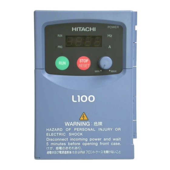
• Power LED - This LED is On when the power input to the inverter is on. Toll Free: voice: 1-877-539-2542 fax: 1-800-539-2542 www.mgitech.com Technologies Inc. Parameter Display POWER HITACHI STOP STOP STOP STOP RESET Run Button Stop/Reset Button 2–19 L100 Inverter Power LED Display Units Hertz / Amperes LEDs Potentiometer Enable LED Potentiometer... - Page 51 ) Keys - Use these keys ) Key - When the unit is in Type (Category) of Function Monitoring functions Basic profile parameters Standard functions Fine tuning functions Intelligent terminal functions Error codes POWER HITACHI STOP STOP STOP STOP RESET FUNC. Function Up/Down Store...
-
Page 52: Keypad Navigational Map
Keypad Navigational Map The L100 Series inverter drives have many programmable functions and parameters. Chapter 3 will cover these in detail, but we need to access just a few items to perform the powerup test. The menu structure makes use of function codes and parameter codes to allow programming and monitoring with only a 4-digit display and a few buttons and LEDs. - Page 53 2–22 Using the Front Panel Keypad Selecting Functions and Editing Parameters In order to run the motor for the powerup test, this section will show how to: • select the inverter’s maximum output frequency to the motor • select the keypad potentiometer as the source of motor speed command •...
- Page 54 FUNC. key. key. Action Display key. key. FUNC. key. key. L100 Inverter Func./Parameter Speed command source setting 0 = potentiometer 1 = control terminals (default) 2 = keypad 0 = potentiometer (selected) Stores parameter, returns to “A” group list Func./Parameter...
-
Page 55: Running The Motor
Display key. key three times. key. d 01 function code appeared, the PRG LED went off. This confirms the key, the display shows the current speed POWER HITACHI STOP STOP STOP STOP RESET Func./Parameter “A” group selected Output frequency selected... - Page 56 State of Inverter at Stop - If you adjust the motor’s speed to zero, the motor will slow to a near stop, and the inverter turns the outputs off. The high-performance L100 can rotate at a very slow speed with high torque output, but not zero (must use servo systems with position feedback for that feature).
-
Page 57: Configuring Drive Parameters
Configuring Drive Parameters In This Chapter... — Choosing a Programming Device ... 2 — Using Keypad Devices ... 3 — Using the PC Software — DOP Plus ... 6 — “D” Group: Monitoring Functions... 8 — “F” Group: Main Profile Parameters ... 9 —... -
Page 58: Choosing A Programming Device
Choosing a Programming Device Introduction Hitachi variable frequency drives (inverters) use the latest electronics technology for getting the right AC waveform to the motor at the right time. The benefits are many, including energy savings and higher machine output or productivity. The flexibility required to handle a broad range of applications has required ever more configurable options and parameters —... -
Page 59: Using Keypad Devices
Using Keypad Devices Inverter Font Panel Keypad The L100 Series inverter front keypad contains all the elements for both monitoring and programming parameters. The keypad layout is pictured below. All other programming devices for the inverter have a similar key arrangement and function. The DOP Plus PC software has an on-screen keypad as well. - Page 60 3–4 Using Keypad Devices Keypad Navigational Map Whether you use the keypad on the inverter, the DOP software for the personal computer, or the hand-held digital operator panel, each navigates the same way. The diagram below shows the basic navigational map of parameters and functions. Display Data NOTE: The inverter 7-segment display shows lower case “b”...
-
Page 61: Operational Modes
The Operator Monitor can view (but not edit) parameters. See Appendix B for DOP monitor and function tables. Contact your local Hitachi distributor for more product information. Toll Free: voice: 1-877-539-2542 fax: 1-800-539-2542 www.mgitech.com Technologies Inc. -
Page 62: Using The Pc Software - Dop Plus
The RS422 electrical characteristics are more noise-immune to electrical interference from inverters and large motors. We recommend that you keep the communications cable away from inverter power supply or motor wiring as a precaution. When you connect the cable and go on-line with the DOP software, the inverter keypad is disabled (except for the Stop/Reset key). -
Page 63: Programming With Dop Plus
3–7 L100 Inverter Programming with the DOP Plus The screen arrangement is similar to the inverter keypad. Additional buttons Read EEPROM and Write EEPROM let you upload or download parameter settings. After doing a Read EEPROM, all the inverter’s parameter settings will be accessi- ble in the scrollable list box. -
Page 64: D" Group: Monitoring Functions
3–8 “D” Group: Monitoring Functions “D” Group: Monitoring Functions Parameter Monitoring Functions You can access important system parameter values with the “D” group monitoring functions, whether the inverter is in Run Mode or Stop Mode. After selecting the function code number for the parameter you want to monitor, press the Function key once to show the value on the display. -
Page 65: F" Group: Main Profile Parameters
“F” Function Name Description Standard default target frequency that determines constant motor speed Standard default acceleration Standard default deceleration Two options; select codes: 00 .. Forward 01 .. Reverse L100 Inverter DOP,DRW,DOP+ Run- Range time Func. Name Edit Units Code —... -
Page 66: A" Group: Standard Functions
3–10 “A” Group: Standard Functions “A” Group: Standard Functions Basic Parameter Settings These settings affect the most fundamental behavior of the inverter — the outputs to the motor. The frequency of the inverter’s AC output determines the motor speed. You may select from three different sources for the reference speed. - Page 67 Two options; select codes: 00... Use offset (A11 value) 01... Use 0 Hz Range n = 1 to 8, where n = number of samples for avg. L100 Inverter Frequency A15 = 00 A15 = 01 % input scale...
- Page 68 “A” Group: Standard Functions Multi-speed Frequency Setting The L100 inverter has the capability to store and output up to 16 frequencies to the motor (A20 to A35). As in traditional motion terminology, we call this multi-speed profile capability. Binary-encoded logic inputs select the particular frequency (speed) setting, and the inverter applies the current acceleration or deceleration setting required to change from the current output frequency to the new one.
- Page 69 Toll Free: voice: 1-877-539-2542 fax: 1-800-539-2542 www.mgitech.com Technologies Inc. A44 = 00 Constant A44 = 01 torque Reduced torque frequency L100 Inverter A42 = 11 100% Torque boost 11.8% frequency 6.0Hz 30.0Hz f base = 60Hz A43 = 10.0%...
- Page 70 3–14 “A” Group: Standard Functions The following table shows the methods of torque control selection. Func. Name Code Torque boost method selection Manual torque boost value Manual torque boost frequency adjustment V/F characteristic curve selection V/F gain setting Toll Free: voice: 1-877-539-2542 fax: 1-800-539-2542 www.mgitech.com Technologies Inc.
- Page 71 (motor free runs until DC braking begins) Applied level of DC braking force, settable from 0 to 100% Sets the duration for DC braking, range is 0.1 to 60.0 seconds 3–15 L100 Inverter Running Free run DC braking time Defaults DOP,DRW,DOP+ Run- time Func.
- Page 72 3–16 “A” Group: Standard Functions Frequency-related Functions The inverter output generates a variable-frequency waveform that determines the motor speed (minus slip losses). You can configure the lower frequency limit to be greater than zero as shown in the graph (below left). The upper limit must not exceed the rating of the motor or capability of the machinery.
-
Page 73: Pid Control
Process Variable (PV) scale factor (multiplier), range of 0.01 to 99.99 Selects source of Process Variable (PV), option codes: 00... “OI” terminal (current in) 01... “O” terminal (voltage in) 3–17 L100 Inverter Defaults DOP,DRW,DOP+ Run- time Func. Units Name Edit Code —... - Page 74 3–18 “A” Group: Standard Functions Automatic Voltage Regulation (AVR) Function The automatic voltage regulation (AVR) feature keeps the inverter output waveform at a relatively constant amplitude during power input fluctuations. This can be useful if the installation has an erratic power source. However, the inverter cannot boost its motor output to a voltage higher than the power input voltage.
- Page 75 Second Acceleration and Deceleration Functions The L100 inverter features two-stage acceleration and deceleration ramps. This gives flexibility in the profile shape, and can avoid jerk (mechanical shock) while approaching steady frequency (or stop) more gently. You can specify the frequency transition point, the point at which the standard acceleration (F02) or deceleration (F03) changes to the second acceleration (A92) or deceleration (A93).
- Page 76 3–20 “A” Group: Standard Functions Func. Name Code Dec1 to Dec2 frequency transition point Acceleration curve selection Deceleration curve setting NOTE: For A95 and A96, if you set a very rapid Acc1 or Dec1 time (less than 1.0 second), the inverter may not be able to change rates to Acc2 or Dec2 before reaching the target frequency.
-
Page 77: B" Group: Fine Tuning Functions
Time delay after under-voltage condition goes away, before the inverter runs motor again. Range is 0.3 to 100 seconds. 3–21 L100 Inverter failure Defaults DOP,DRW,DOP+ Run- time Func. Units... - Page 78 3–22 “B” Group: Fine Tuning Functions Electronic Thermal Overload Alarm Setting The thermal overload detection protects the inverter and motor from excessive heat. First use B13 to select the torque charac- teristic as a function of frequency. For example, a motor can overheat if it runs for too long at a low speed.
- Page 79 150% of the rated current of the inverter, setting resolution is 1% of rated current Sets the deceleration rate when inverter detects overload, range is 0.1 to 30.0, resolution is 0.1. 3–23 L100 Inverter restriction area time Defaults DOP,DRW,DOP+ Run- time Func.
- Page 80 3–24 “B” Group: Fine Tuning Functions Software Lock Mode The software lock function keeps personnel from accidentally changing parameters in the inverter memory. The feature has some options, but the software lock function (B21) is not protected from operator editing. You can lock all other parameters except the output frequency (F01), if desired.
- Page 81 (reactive current) to improve D02 display accuracy, range is 0 to 32 Amperes Adjust 8-bit gain to analog meter connected to terminal FM, range is 0 to 255 3–25 L100 Inverter Defaults DOP,DRW,DOP+ Run- time Func. Units Name...
- Page 82 3–26 “B” Group: Fine Tuning Functions Func. Name Code Start frequency adjustment Carrier frequency setting Initialization mode (parameters or trip history) Country code for initialization Frequency scalar conversion factor STOP key enable Resume on FRS cancellation mode Data select for digital operator OPE-J Toll Free: voice: 1-877-539-2542 fax: 1-800-539-2542 www.mgitech.com Technologies Inc.
-
Page 83: C" Group: Intelligent Terminal Functions
Functions and Options –The function codes in the following table let you assign one of fifteen options to any of the five logic inputs for the L100 inverters. The functions C01through C05 configure the terminals 1 through 5 respectively. The “value” of these particular parameters is not a scalar value, but it is a discrete number that selects one option from two or more available options. - Page 84 3–28 “C” Group: Intelligent Terminal Functions The input logic convention is programmable for each of the five inputs. Most inputs default to normally open (active high), but you can select normally closed (active low) in order to invert the sense of the logic. Func.
- Page 85 Reset Unattended Start On powerup, the inverter will not resume a Protection Run command (mostly used in the US) On powerup, the inverter will resume a Run command that was active before power loss 3–29 L100 Inverter Description...
- Page 86 The parameters may be edited and stored Analog Input Terminal OI is enabled for current input Voltage/current (uses terminal L for power supply return) Select Terminal O is enabled for voltage input (uses terminal L for power supply return) Reset Inverter...
- Page 87 Select logic convention, two option codes: 00... normally open [NO] 01... normally closed [NC] Select logic convention, two option codes: 00... normally open [NO] 01... normally closed [NC] 3–31 L100 Inverter Defaults DOP,DRW,DOP+ Run- time Func. Units Name Edit Code —...
- Page 88 3–32 “C” Group: Intelligent Terminal Functions The output logic convention is programmable for terminals 11 and 12. The open-collec- tor output terminals 11 and 12 default to normally open (active low), but you can select normally closed (active high) for terminals 11 and 12 in order to invert the sense of the logic.
- Page 89 It reaches 100% duty cycle when the output reaches 200% of the rated inverter current. Digital frequency FM (frequency-modulated) voltage output with a constant output monitor 50% duty cycle. Its frequency = inverter output frequency. 3–33 L100 Inverter Description Description...
- Page 90 3–34 “C” Group: Intelligent Terminal Functions Output Function Adjustment Parameters The overload level parameter (C41)sets the motor current level at which the overload signal becomes true. The range of settings is from 0% to 200% of the rated current for the inverter. This function is for gener- ating an early warning logic output, without causing either a trip event or a restriction of the motor current (those...
- Page 91 L – O (voltage input) and the frequency output Scale factor between the external frequency command on terminals L – OI (current input) and the frequency output 3–35 L100 Inverter Defaults DOP,DRW,DOP+ Run- time Func. Units Name...
- Page 92 Operations and Monitoring In This Chapter... — Introduction ... 2 — Connecting to PLCs and Other Devices ... 4 — Using Intelligent Input Terminals ... 6 — Using Intelligent Output Terminals ... 18 — Analog Input Operation ... 24 — Analog and Digital Monitor Output ... 25 —...
-
Page 93: Introduction
This chapter shows the parameters and input/output terminals associated with PID loop operation. 5. Multiple motors – a single L100 inverter may be used with two or more motors in some types of applications. This chapter shows the electrical connections involved in multiple-motor applications. - Page 94 Otherwise, it may cause injury to personnel. WARNING: If the power supply is cut off for a short period of time, the inverter may restart operation after the power supply recovers if the command to operate is active. If a restart may pose danger to personnel, so be sure to use a lock-out circuit so that it will not restart after power recovery.
-
Page 95: Connecting To Plcs And Other Devices
Connecting to PLCs and Other Devices Connecting to PLCs and Other Devices Hitachi inverters (drives) are useful in many types of applications. During installation, the inverter keypad (or other programming device) will facilitate the initial configura- tion. After installation, the inverter will generally receive its control commands through the control logic connector or serial interface from another controlling device. - Page 96 30 VDC, 3.0A (R load) max. 30 VDC, 0.7A (I load, P.F.=0.4) max. Relay contact, normally open 5 VDC, 100mA min. during RUN The two terminals “L” are electrically connected together inside the inverter. L100 Inverter AL0 AL1 AL2 Relay contacts Ratings 4–5...
-
Page 97: Using Intelligent Input Terminals
(isolated) +24V field supply (P24) to power the inputs. The input circuits are internally connected to the power supply ground. As the diagram shows, you can use a switch (or jumper) to activate an input terminal which has been programmed. - Page 98 Binary encoded speed select, Bit 2, logical 0 Multi-speed select, Binary encoded speed select, Bit 3, logical 1 Bit 3 (MSB) Binary encoded speed select, Bit 3, logical 0 4–7 L100 Inverter Input Function Multi- speed Speed 1 Speed 2...
- Page 99 4–8 Using Intelligent Input Terminals Option Terminal Code Symbol Valid for inputs: Required settings: Notes: • When programming the multi-speed settings, be sure to press the Store key each time and then set the next multi-speed setting. Note that when the key is not pressed, no data will be set.
- Page 100 Inverter is in Stop Mode C01, C02, C03, C04, C05 Example: A02= 01, A38 > B82, A38 > 0, value is 0 Hz. See I/O specs on page 4–5. L100 Inverter [JG] terminal [FW, RV] (Run) Motor speed...
- Page 101 4–10 Using Intelligent Input Terminals Two-stage Acceleration and Deceleration When terminal [2CH] is turned on, the inverter changes the rate of acceleration and deceleration from the initial settings (F02 and F03) to use the second set of acceleration/ deceleration values. When the terminal is turned off, the equipment is returned to the original acceleration and deceleration time (F02 acceleration time 1, and F03 decelera-...
- Page 102 (coast) to stop Output operates normally, so controlled deceler- ation stops motor C01, C02, C03, C04, C05 Example: B03, B88, C11 to C15 See I/O specs on page 4–5. 4–11 L100 Inverter B03 wait time time Description FW FRS...
-
Page 103: External Trip
4–12 Using Intelligent Input Terminals External Trip When the terminal [EXT] is turned on, the inverter enters the trip state, indicates error code E12, and stops the output. This is a general purpose interrupt type feature, and the meaning of the error depends on what you connect to the [EXT] terminal. When the switch between the set terminals [EXT] and [P24] is turned on, the equipment enters the trip state. -
Page 104: Unattended Start Protection
Input Function Name State Unattended Start Protection C01, C02, C03, C04, C05 (none) L100 Inverter time Alarm cleared command Description On powerup, the inverter will not resume a Run command (mostly used in the US) On powerup, the inverter will resume a Run... -
Page 105: Software Lock
4–14 Using Intelligent Input Terminals Software Lock When the terminal [SFT] is turned on, the data of all the parameters and functions except the output frequency is locked (prohibited from editing). When the data is locked, the keypad keys cannot edit inverter parameters. To edit parameters again, turn off the [SFT] terminal input. - Page 106 Terminal O is enabled for voltage input (uses terminal L for power supply return) C01, C02, C03, C04, C05 Example: A01 = 01 See I/O specs on page 4–5. 4–15 L100 Inverter Description 4-20 mA when AT= On 0-10 V when AT= Off + –...
-
Page 107: Reset Inverter
4–16 Using Intelligent Input Terminals Reset Inverter The [RS] terminal causes the inverter to execute the reset operation. If the inverter is in Trip Mode, the reset cancels the Trip state. When the switch between the set terminals [RS] and [P24] is turned on and off, the inverter executes the reset operation. - Page 108 L, the inverter checks for over-temperature and will cause trip event and turn off output to motor OPEN A disconnect of the thermistor causes a trip event, and the inverter turns off the motor C05 only Example: (none) 4–17 L100 Inverter Description thermistor MOTOR...
-
Page 109: Using Intelligent Output Terminals
4–18 Using Intelligent Output Terminals Using Intelligent Output Terminals The intelligent output terminals are programmable in a similar way to the intelligent input terminals. The inverter has several output functions which you can assign individu- ally to three physical logic outputs. Two of the outputs are open-collector transistors, and the third output is the alarm relay (form C –... - Page 110 11, 12, AL0 – AL2 Example: (none) L100 Inverter Output frequency 1.5 Hz accel. 0.5 Hz decel. signal Description See I/O specs on page 4–5.
-
Page 111: Overload Advance Notice Signal
4–20 Using Intelligent Output Terminals Overload Advance Notice Signal When the output current exceeds a preset value, the [OL] terminal signal turns on. The parameter C41 sets the overload threshold. The overload detection circuit operates during powered motor operation and during regenerative braking. The output circuits use open-collector transistors, and are active low. -
Page 112: Output Deviation For Pid Control
PID control the deviation signal when PID error is less than the set threshold for the deviation signal 11, 12, AL0 – AL2 Example: See I/O specs on page 4–5. 4–21 L100 Inverter Error Process variable Setpoint [OD] Signal time Description... -
Page 113: Alarm Signal
AL0-AL2. • See the description of AL1, AL2, and AL0. • When the inverter power supply is turned off, the alarm signal output is valid as long as the external control circuit has power. • This signal output has the delay time (300ms nominal) from the fault alarm output. - Page 114 AL0 AL1 AL2 AL0- AL0- Contact State Normal Closed Open N.O. (set Trip Open Closed C33=00) – Open Closed 4–23 L100 Inverter When an alarm occurs AL0 AL1 AL2 AL0- AL0- Power State Normal Open Closed Trip Closed Open – Open Closed...
-
Page 115: Analog Input Operation
4–24 Analog Input Operation Analog Input Operation The L100 inverters provide for analog input to command the inverter frequency output value. The analog input terminal group includes the L, OI, O, and H terminals on the control connector, which provide for Voltage [O] or Current [OI] input. -
Page 116: Analog And Digital Monitor Output
Digital monitor output frequency, frequency-modulated format Pulse-width modulation (analog) [FM] Output value -- - time T = 4 ms 4–25 L100 Inverter A GND Analog/digital Output See I/O specs on page 4–5. – 0 to 10V, 1 mA C23 = 00... - Page 117 4–26 Analog and Digital Monitor Output Current Monitor, PWM Signal – (C23 = 01) – The [FM] output duty cycle varies with the inverter output current to the motor. The signal period T is fixed at 4 ms, and the amplitude is fixed at 10 VDC.
-
Page 118: Pid Loop Operation
(Target) Scale factor Frequency reciprocal source select 1/A75 Process Variable (Feedback) Analog input scaling A13 A14 PID V/I input select L100 Inverter External Motor Process Process Variable (PV) Sensor Scale factor P gain Frequency Error setting I gain D gain... -
Page 119: Configuring The Inverter For Multiple Motors
4–28 Configuring the Inverter for Multiple Motors Configuring the Inverter for Multiple Motors Simultaneous Connections For some applications, you may need to connect two or more motors (wired in parallel) to a single inverter’s output. For example, this is common in conveyor applications where two separate conveyors need to have approximately the same speed. -
Page 120: Chapter 5: Motor Control Accessories
Motor Control Accessories In This Chapter... — Introduction ... 2 — Component Descriptions... 3 Toll Free: voice: 1-877-539-2542 fax: 1-800-539-2542 www.mgitech.com Technologies Inc. page... -
Page 121: Introduction
– NOTE: The Hitachi part number series for accessories includes different sizes of each part type, specified by the –x suffix. Hitachi product literature can help match size and rating of the your inverter to the proper accessory size. RF noise... -
Page 122: Component Descriptions
• If the unbalanced factor of the power supply is 3% or higher • If the power supply capacity is at least 10 times greater than the inverter capacity (the power supply capacity is 500 kVA or more) •... - Page 123 EMI Filter The EMI filter reduces the conducted noise on the power supply wiring generated by the main power supply, protecting the inverter. Connect the EMI filter to the inverter primary (input side). The FFL100 series filter is required for compliance to the EMC directive (Europe) and C-TICK (Australia).
-
Page 124: Dynamic Braking
The L100 inverter can connect to an external braking unit, which accepts the excess energy from the motor during deceleration to its internal resis- tor(s). - Page 125 5–6 Component Descriptions The following table specifies the braking options for 400V class L100 inverters and the braking torque for each option. Use BRD–EZ2 braking unit for 400V class inverters. L100 Inverter 400V Models Model Number 004HFE/HFU 007HFE/HFU 015HFE/HFU 022HFE/HFU...
-
Page 126: Troubleshooting
Troubleshooting and Maintenance In This Chapter... — Troubleshooting... 2 — Monitoring Trip Events, History, & Conditions .. 5 — Restoring Factory Default Settings ... 8 — Maintenance and Inspection ... 9 — Warranty... 14 Toll Free: voice: 1-877-539-2542 fax: 1-800-539-2542 www.mgitech.com Technologies Inc. -
Page 127: Troubleshooting
Please read the following safety messages before troubleshooting or performing mainte- nance on the inverter and motor system. WARNING: Wait at least five (5) minutes after turning off the input power supply before performing maintenance or an inspection. Otherwise, there is the danger of electric shock. -
Page 128: Troubleshooting Tips
U/T1,V/T2, and W/T3? • Are the control terminals [FW] and [RV] wired correctly? • Is parameter F04 properly set? L100 Inverter Solution • Make sure the parameter setting A01 is correct. • Make sure the parameter setting A02 is correct. - Page 129 Heavy loads activate the overload restriction feature (reduces output as needed). • Increase the motor capacity (both inverter and motor). • Fix power supply problem. • Change the output frequency slightly, or use the jump frequency setting to skip the problem frequency. •...
-
Page 130: Monitoring Trip Events, History, & Conditions
Error Code FUNC. Output frequency at trip point FUNC. Motor current at trip point FUNC. DC bus voltage at trip point FUNC. No error FUNC. L100 Inverter STOP STOP STOP STOP RESET Stop STOP STOP STOP STOP RESET Fault Trip... -
Page 131: Error Codes
6–6 Monitoring Trip Events, History, & Conditions Error Codes An error code will appear on the display automatically when a fault causes the inverter to trip. The following table lists the cause associated with the error. Error Code Toll Free: voice: 1-877-539-2542 fax: 1-800-539-2542 www.mgitech.com Technologies Inc. - Page 132 When intelligent terminal 5 is configured for PTC (protective thermistor) function and the inverter has sensed the resistance is too high (wire is broken or temperature is too high), the inverter trips and turns off the output. 6–7 L100 Inverter Cause(s)
-
Page 133: Restoring Factory Default Settings
6–8 Restoring Factory Default Settings Restoring Factory Default Settings You can restore all inverter parameters to the original factory (default) settings, for the intended country of use. After initializing the inverter, use the powerup test in Chapter 2 to get the motor running again. To initialize the inverter, follow the steps below. 1. -
Page 134: Maintenance And Inspection
The life of a capacitor is affected by the ambient temperature. See the Capacitor Life Curve on the next page. The inverter must be cleaned periodically. If dust accumulates on the fan and heat sink, it can cause overheating of the inverter. L100 Inverter Inspection Criteria Method... -
Page 135: Spare Parts
6–10 Maintenance and Inspection Spare parts We recommend that you stock spare parts to reduce down time, which include: Part description Cooling fan Case Capacitor Life Curve The DC bus inside the inverter uses a large capacitor as shown in the diagram below. The capacitor handles high voltage and current as it smooths the power for use by the inverter. - Page 136 The inverter output has a distorted waveform, and low frequencies may cause erroneous readings. However, the measuring instruments and methods listed above provide comparably accurate results. A general-purpose digital volt meter (DVM) is not usually suitable to measure a distorted waveform (not pure sinusoid). L100 Inverter Notes Reference Value Fundamental Commercial...
- Page 137 6–12 Maintenance and Inspection The figures below show measurement locations for voltage, current, and power measure- ments listed in the table on the previous page. The voltage to be measured is the funda- mental wave effective voltage. The power to be measured is the total effective power. Single-phase measurement diagram Three-phase measurement diagram Conduct the insulation resistance test by short circuiting the terminals as shown below.
- Page 138 Toll Free: voice: 1-877-539-2542 fax: 1-800-539-2542 www.mgitech.com Technologies Inc. U/T1 V/T2 Inverter W/T3 220 k – Diode bridge Voltmeter L100 Inverter Voltage measurement without load U/T1 L1(L) V/T2 Inverter W/T3 L3(N) Additional resistor 220 k –...
-
Page 139: Warranty
Malfunction or damage caused by a drop after purchase and transportation c. Malfunction or damage caused by fire, earthquake, flood, lightening, abnormal input voltage, contamination, or other natural disasters associated with field repair shall be charged to the purchaser. your Hitachi distributor to purchase replacement or additional manuals. -
Page 140: Appendix A: Glossary And Bibliography
Glossary and Bibliography In This Appendix... — Glossary ... 2 — Bibliography ... 8 Toll Free: voice: 1-877-539-2542 fax: 1-800-539-2542 www.mgitech.com Technologies Inc. page... -
Page 141: Glossary
Auto tuning is a common feature of process controllers with PID loops. Hitachi inverters (such as SJ100 series) feature auto-tuning to determine motor parameters for optimal commuta- tion. - Page 142 Dead band may or may not be desirable; it depends on the needs of the application. For Hitachi inverters, “digital operator panel” (DOP) refers first to the operator keypad on the front panel of the inverter. It also includes hand-held remote keypads, which connect to the inverter via a cable.
- Page 143 A device that electronically changes DC to AC current through a alternating process of switching the input to the output, inverted and non-inverted. A variable speed drive such as the Hitachi L100 is also called an inverter, since it contains three inverter circuits to generate 3-phase output to the motor.
- Page 144 The ability of a motor drive to store preset discrete speed levels for the motor, and control motor speed according to the currently selected speed preset. The Hitachi inverters have 16 preset speeds. In motor terminology, motor load consists of the inertia of the physical mass that is moved by the motor and the related friction from guiding mechanisms.
- Page 145 Hot varies sinusoidally above and below Neutral. This power source is named Single Phase to differentiate it from three-phase power sources. Some Hitachi inverters can accept single phase input power, but they all output three-phase power to the motor. See also three-phase.
- Page 146 Amperes or more, all with high reliability. The saturation voltage has been decreasing, resulting in less heat dissipation. Hitachi inverters use state-of-the-art semiconductors to provide high perfor- mance and reliability, all in a compact package. See also IGBT and saturation voltage.
-
Page 147: Bibliography
Toll Free: voice: 1-877-539-2542 fax: 1-800-539-2542 www.mgitech.com Technologies Inc. Title Phipps, Clarence A. The Fairmont Press, Inc. / Prentice-Hall, Inc. 1997 ISBN 0-13-636390-3 Brumbach, Michael E. Delmar Publishers 1997 ISBN 0-8273-6937-9 Published by Hitachi, Ltd. Japan 1995 Publication SIG-E002 Author and Publisher... -
Page 148: Appendix B: Drive Parameter Settings Tables
Drive Parameter Settings Tables In This Appendix... — Introduction ... 2 — Parameter Settings for Keypad Entry... 2 — Parameter Settings for DOP/DRW/DOP Plus .. 7 Toll Free: voice: 1-877-539-2542 fax: 1-800-539-2542 www.mgitech.com Technologies Inc. page... -
Page 149: Introduction
Introduction Introduction This appendix lists the user-programmable parameters for the L100 series inverters and the default values for European and U.S. product types. The right-most column of the tables is blank, so you can record values you have changed from the default. This involves just a few parameters for most applications. -
Page 150: Standard Functions
Multi-speed 15 setting Jog frequency setting Jog stop mode Torque boost method selection Manual torque boost value Toll Free: voice: 1-877-539-2542 fax: 1-800-539-2542 www.mgitech.com Technologies Inc. Default Setting Name -FE (Europe) 50.0 50.0 B–3 L100 Inverter User Setting -FU (USA) 60.0 60.0... - Page 151 B–4 Parameter Settings for Keypad Entry “A” Group Parameters Func. Code Manual torque boost frequency adjustment V/F characteristic curve selection V/F gain setting DC braking enable DC braking frequency setting DC braking wait time DC braking force setting DC braking time setting Frequency upper limit setting Frequency lower limit setting A63, A65,...
- Page 152 Technologies Inc. Default Setting Name -FE (Europe) Rated current for each inverter Rated current x 1.25 Rated current x 0.58 B–5 L100 Inverter User Setting -FU (USA) Rated current for each inverter Rated current x 1.25 Rated current x 0.58...
- Page 153 B–6 Parameter Settings for Keypad Entry Intelligent Terminal Functions “C” Group Parameters Func. Code Terminal 1 function Terminal 2 function Terminal 3 function Terminal 4 function Terminal 5 function Terminal 1 active state Terminal 2 active state Terminal 3 active state Terminal 4 active state Terminal 5 active state Terminal 11 function (logical)
- Page 154 Parameter Settings for DOP/DRW/DOP Plus L100 series inverters provide many functions and parameters which can be configured by the user. We recommend that you record all parameters which have been edited, in order to help in troubleshooting or recovery from a loss of parameter data.
- Page 155 B–8 Parameter Settings for DOP/DRW/DOP Plus Monitor Mode Setup Func. Name Code Mon. Alarm display Total alarm count Trip history, previous alarm (example) Trip history, 2nd previous alarm Function Mode Setup Function Mode Setup Func. Name Code F-00 Base frequency setting F-01 Maximum frequency setting...
- Page 156 DCB F DCB WAIT 0.0s DCB WAIT 0.0s DCB V DCB V DCB T 00.0s DCB T IPS UVTIME 01.0s IPS UVTIME 01.0s IPS WAIT 001.0s IPS WAIT 001.0s IPS POWR IPS POWR B–9 L100 Inverter User Setting 00.5Hz 00.0s...
-
Page 157: Parameter Settings For Dop/Drw/Dop Plus
B–10 Parameter Settings for DOP/DRW/DOP Plus Function Mode Setup Func. Name Code F-23 Electronic thermal cut- off characteristic Electronic thermal level F-24 Overload limit setting Overload limit constant Overload limit load F-25 Software lock selection F-26 Frequency lower limit Frequency upper limit F-27 Jump frequency 1 Jump frequency 2... - Page 158 IN-TM O/C-4 NC IN-TM O/C-5 NO IN-TM O/C-5 NO OUT-TM 1 OUT-TM 1 OUT-TM 2 OUT-TM 2 OUT-TM O/C-A NC OUT-TM O/C-A NC OUT-TM O/C-1 NO OUT-TM O/C-1 NO OUT-TM O/C-2 NO OUT-TM O/C-2 NO CARRIER 05.0kHz B–11 L100 Inverter User Setting...
- Page 159 B–12 Parameter Settings for DOP/DRW/DOP Plus Function Mode Setup Func. Name Code F-37 Monitor signal selection MONITOR F-38 Initialization country code for default settings Debug mode display selection Motor rotation direction INIT DOPE FWD Initial mode selection F-43 PID loop enable PID proportional gain PID integral gain PID derivative gain...
- Page 160 Index A Group standard functions 3–10 AC motor 1–9 AC reactors 5–3 Acceleration 3–9, 3–19 two-stage 4–10 Access levels 2–2 Accessories 5–2 Air flow 2–7 Alarm signal 4–22 Alarm terminals 4–5 Analog I/O terminals 4–5 Analog input operation 4–24 current/voltage select 4–15 Analog input settings 3–11 Analog output operation 4–25 current/voltage select 4–15...
- Page 161 Index–2 Editing parameters 2–22 EEPROM 1–10 Electronic thermal overload alarm 3–22 EMI filter 5–4 Environmental conditions 6–9 Environmental specs 1–6 Error codes 6–6 Event clearing 4–16 External frequency command 3–11 External trip event 4–12 F Group functions 3–9 Factory default settings 6–8 Fault 4–22 Faults 6–5 Features 1–2, 2–2...
- Page 162 Proportional gain 3–17 PTC thermistor thermal protection 4–17 Pulse-width modulation 4–25 PV source setting 3–17 Toll Free: voice: 1-877-539-2542 fax: 1-800-539-2542 www.mgitech.com Technologies Inc. L100 Inverter Reduced torque 3–5, 3–13 Relay contacts 4–22 Reset function 4–16 Resistor braking 5–5 Restart mode 3–21 Reverse run command 4–6...
- Page 163 Index–4 Unattended Start Protection 4–13 USP 4–13 V/F characteristics 3–13 Variable-frequency control 3–5 Variable-frequency drive definition 1–7 Velocity profile 1–11 Ventilation 2–7 Toll Free: voice: 1-877-539-2542 fax: 1-800-539-2542 www.mgitech.com Technologies Inc. Warranty 6–14 Wiring caution messages 2–12 gauge 2–13 input power 2–14 output to motor 2–16...