Advertisement
C
C
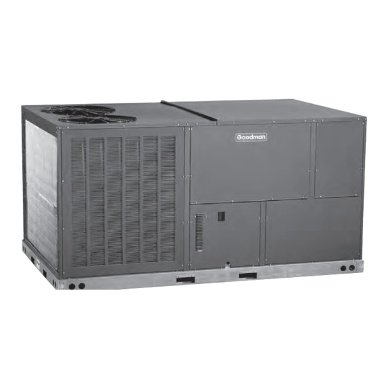
: 90,000 - 146,000 Btu/
ooling
apaCity
Standard Features
• R-410A chlorine-free refrigerant
• High-efficiency scroll compressors
• Two-stage cooling
• Copper tube / aluminum fin coils
• Contactor with lugs
• High- and low-pressure switches
• High-capacity, steel-cased filter drier
• Heater kits with single-point entry
• 24-volt terminal strip
• Convertible
• Easy to service
• Built-in filter rack with standard 2" filters
• Bottom utility entry
• AHRI Certified; ETL Listed
Cabinet Features
• Heavy-gauge, galvanized-steel cabinet with
UV-resistant powder-paint finish
• Full Perimeter Rail
* Complete warranty details available from your local dealer or at www.goodmanmfg.com.
SS-CPC90-150
7½-
h
Contents
Nomenclature ........................................................................2
Product Specifications ...........................................................3
Airflow Data ...........................................................................7
Heat Kit Electrical Data . ......................................................11
Expanded Cooling Data .......................................................16
Dimensions ..........................................................................26
Wiring Diagrams .................................................................30
Accessories ...........................................................................34
www.goodmanmfg.com
CpC C
ommERCial
12½-t
t
to
on
hREE
p
a
C
aCkagEd
iR
onditionERs
11.5 EER
up to
-p
hasE
4/12
Supersedes 2/12
Advertisement

Related Manuals for Goodman CPC CONVERCIAL SS-CPC90-150


Summary of Contents for Goodman CPC CONVERCIAL SS-CPC90-150
-
Page 1: Table Of Contents
: 90,000 — 146,000 Btu/ ooling apaCity Standard Features • R-410A chlorine-free refrigerant • High-efficiency scroll compressors • Two-stage cooling • Copper tube / aluminum fin coils • Contactor with lugs • High- and low-pressure switches • High-capacity, steel-cased filter drier • Heater kits with single-point entry • 24-volt terminal strip • Convertible • Easy to service • Built-in filter rack with standard 2” filters • Bottom utility entry • AHRI Certified; ETL Listed Cabinet Features • Heavy-gauge, galvanized-steel cabinet with UV-resistant powder-paint finish • Full Perimeter Rail * Complete warranty details available from your local dealer or at www.goodmanmfg.com. -
Page 2: Nomenclature
RoduCt pECifiCations omEnClatuRE Brand Commercial Configura7on Packaged U nit Applica7on Cooling Gas H eat Heat P ump Nominal G ross C ooling C apacity 3 T ons 8½ T ons 4 ... -
Page 3: Product Specifications
— 7½ t roduct PecificationS Cooling Capacity Total BTU/h Sensible BTU/h EER / IEER Decibels AHRI Reference #s Evaporator Motor / Coil Motor Type Indoor Nominal CFM Indoor Motor FLA (Cooling) Horsepower / RPM Piston Size (Cooling) Filter Size (Qty) Drain Size (NPT) R-410A Refrigerant Charge Cir #1 &... - Page 4 roduct PecificationS — 8½ t roduct PecificationS Cooling Capacity Total, BTU/h Sensible BTU/h EER / IEER Decibels ARI Reference #s Evapoartor Motor / Coil Motor Type Indoor Nominal CFM Indoor Motor FLA (Cooling) Horsepower - RPM Piston Size (Cooling) Filter Size (Qty) Drain Size (NPT) R-410A Refrigerant Charge Cir #1 &...
- Page 5 — 10 t roduct PecificationS Cooling Capacity Total BTU/h Sensible BTU/h EER / IEER Decibels ARI Reference #s Evaporator Motor / Coil Motor Type Indoor Nominal CFM Indoor motor FLA (Cooling) Horsepower - RPM Piston Size (Cooling) Filter Size (Qty) Drain Size (NPT) R-410A Refrigerant Charge Cir #1 &...
- Page 6 roduct PecificationS — 12½ t roduct PecificationS Cooling Capacity Total, BTU/h Sensible BTU/h EER / iEER Decibels ARI Reference #s Evaporator Motor / Coil Motor Type Indoor Nominal CFM Indoor Motor FLA (Cooling) Horsepower - RPM Piston Size (Cooling) Filter Size Drain Size (NPT) R-410A Refrigerant Charge Cir #1 &...
- Page 7 — 7½ t iRflow (“ W.C.) 3400 3303 1.41 2871 2838 1.23 High-Static Belt Drive — Down Shot (for A Models only) (“ W.C.) DO NOT OPERATE 3381 1119 3089 1129 (“ W.C.) 3780 3687 3327 3236 1.39 2850 2713 1.17 High-Static Belt Drive —...
- Page 8 RoduCt pECifiCations — 8½ t iRflow (“ W.C.) 3250 3153 1.38 2721 2688 1.20 (“ W.C.) 3231 1116 3256 1156 2.31 2939 1126 (“ W.C.) 3630 3537 1.57 3177 3086 1.36 2700 2563 1.14 (“ W.C.) 3238 1100 3188 1146 2.23 2809 1111...
- Page 9 — 10 t iRflow (“ W.C.) 4488 4442 2.02 4066 4001 1.77 3622 3603 1.55 (“ W.C.) 4438 1116 3956 1124 4050 1179 3.05 3473 1132 (“ W.C.) 4467 4564 2.06 4170 4129 1.81 3498 3558 1.49 (“ W.C.) DO NOT OPERATE 4760 1105...
-
Page 10: Airflow Data
RoduCt pECifiCations — 12½ t iRflow (" W.C.) 5514 2.92 5349 5204 2.69 4919 4830 2.42 4649 4497 2.19 4264 (" W.C.) 5776 4.64 5510 5465 4.30 5199 5145 3.97 4871 4805 3.63 4565 4429 3.27 4233 (" W.C.) 5871 3.20 5639 5610... - Page 11 lECtRiCal lowER Model and MCA¹ Heat Kit Usage at 208 / 240V CPC090***3B*** EHK3-16 EHK3-30 EHK3-45 Model and MCA¹ Heat Kit Usage at 480V CPC090***4B*** EHK4-16 EHK4-30 EHK4-45 Model and MCA¹ Heat Kit Usage at 575V CPC090***7B*** EHK7-16 EHK7-30 EHK7-45 ¹...
- Page 12 RoduCt pECifiCations lECtRiCal lowER Model and MCA¹ Heat Kit Usage at 208 / 240V CPC102***3B*** EHK3-16 EHK3-30 EHK3-45 Model and MCA¹ Heat Kit Usage at 480V CPC102***4B*** EHK4-16 EHK4-30 EHK4-45 Model and MCA¹ Heat Kit Usage at 575V CPC102***7B*** EHK7-16 EHK7-30 EHK7-45 ¹...
- Page 13 lECtRiCal lowER Model and MCA¹ Heat Kit Usage at 208 / 240V CPC120***3B*** EHK3-16 48 / 55 EHK3-30 87 / 100 EHK3-45 121 / 139 Model and MCA¹ Heat Kit Usage at 208 / 240V CPC120***3H*** EHK3-16 49 / 57 EHK3-30 88 / 102 EHK3-45...
-
Page 14: Heat Kit Electrical Data
roduct PecificationS lectrical lower Model and MCA¹ Heat Kit Usage at 208 / 240V CPC150***3B*** EHK3-16 EHK3-30 EHK3-45 Model and MCA¹ Heat Kit Usage at 480V CPC150***4B*** EHK4-16 EHK4-30 EHK4-45 Model and MCA¹ Heat Kit Usage at 575V CPC150***7B*** EHK7-16 EHK7-30 EHK7-45 ¹... - Page 15 RoduCt pECifiCations — 7½ t xpandEd ooling SS-CPC90-150 www.goodmanmfg.com...
- Page 16 RoduCt pECifiCations — 7½ t xpandEd ooling Cont www.goodmanmfg.com SS-CPC90-150...
- Page 17 RoduCt pECifiCations — 8½ t xpandEd ooling SS-CPC90-150 www.goodmanmfg.com...
- Page 18 RoduCt pECifiCations — 8½ t xpandEd ooling Cont www.goodmanmfg.com SS-CPC90-150...
-
Page 19: Expanded Cooling Data
RoduCt pECifiCations — 10 t xpandEd ooling SS-CPC90-150 www.goodmanmfg.com... - Page 20 RoduCt pECifiCations — 10 t xpandEd ooling Cont www.goodmanmfg.com SS-CPC90-150...
- Page 21 RoduCt pECifiCations — 12½ t xpandEd ooling SS-CPC90-150 www.goodmanmfg.com...
- Page 22 RoduCt pECifiCations — 12½ t xpandEd ooling Cont www.goodmanmfg.com SS-CPC90-150...
-
Page 23: Dimensions
APPENDIX C UNIT DIMENSIONS imEnsions 12.5 52 7/8" 52 7/8" 52 7/8" 58 7/8" 28⅜” 7⅜” 28 3/8” 7 3/8” 13⅞” 13 7/8” SUPPLY 6 1/4” 6¼” Horizontal Discharge NOTE For horizontal discharge, remove the supply and return duct covers and place them over the vertical discharge return and supply openings. - Page 24 RoduCt pECifiCations lEaRanCEs Maintain an adequate clearance around the unit for safety, service, maintenance, and proper unit operation. Leave a total clearance of 75” on the main control panel side of the unit for possible removal of fan shaft, coil, electric heat, and gas furnace. Leave a clearance of 48” on all other sides of the unit for possible compressor removal or service access, and to ensure proper ventilation and condenser airflow. Do not install the unit beneath any obstruct- ion. Install the unit away from all building exhausts to inhibit ingestion of exhaust air into the unit’s fresh-air intake. lECtRiCal ntRanCE oCations 11⅝” High-Voltage Entrance ” Low-Voltage Entrance 3” 48” 36” Min. 75” Dimples Mark Drill Locations www.goodmanmfg.com 48” 48” SS-CPC90-150...
- Page 25 — R nstallation igging Provisions for forks have been included in the unit base frame. No other fork locations are approved. • Unit must be lifted by the four lifting holes located at the base frame corners. • Lifting cables should be attached to the unit with shackles. • The distance between the crane hook and the top of the unit must not be less than 60”. • Two spreader bars must span over the unit to prevent damage to the cabinet by the lift cables. Spreader bars must be of sufficient length so that cables do not come in contact with the unit during transport. Remove wood struts mounted beneath unit base frame before setting unit on roof curb. These struts are intended to protect unit base frame from fork lift damage. To remove the struts, extract the sheet metal retainers and pull the struts through the base of the unit. Refer to rig- ging label on the unit. Important: If using bottom discharge with roof curb, duct-work should be attached to the curb prior to installing the unit. Duct-work dimensions are shown in Roof Curb Installation Instructions Manual. Refer to the Roof Curb Installation Instructions for proper curb installation. Curbing must be installed in compliance with the National Roofing Contractors Association Manual.
- Page 26 RoduCt pECifiCations nstallation Cont 3-d V 92¼ 15⅜ x 31⅛ Supply Opening 14⅝ x 38⅜ Return Opening Curb installations must comply with local codes and should follow the established guidelines of the National Roofing Contractors Association. Proper unit installation requires that the roof curb be firmly and permanently attached to the roof structure. Check for adequate fastening method prior to setting the unit on the curb. Full perimeter roof curbs are available from the factory and are shipped unassembled. The installing contractor is responsible for field assembly, squaring, leveling, and mounting on the roof structure. All required hardware necessary for the assembly of the sheet metal curb is included in the curb accessory package.
- Page 27 RoduCt pECifiCations — CpC090-120 iRing iagRam 0907 foR modEls with sERial numBERs and BElow SS-CPC90-150 www.goodmanmfg.com...
- Page 28 RoduCt pECifiCations — CpC090-120 ( iRing iagRam Wiring is subject to change. Always ⚠ refer to the wiring diagram or the unit for the most up-to-date wiring. Cont foR modEls with sERial numBERs High Voltage: Disconnect all power before servicing or installing this unit. Multiple power arning sources may be present.
- Page 29 — CpC090-150 iRing iagRam SMOKE/FIRE DETECTOR REPLACES JUMPER EBTDR XFMR-R XFMR-C NOTE #2 SPEED RCCF2 RD OR Wiring is subject to change. Always ⚠ refer to the wiring diagram or the unit for the most up-to-date wiring. SS-CPC90-150 208 240 COMP2 RCCF1 COMP1...
- Page 30 RoduCt pECifiCations — CpC090-150 ( iRing iagRam SUPPLY VOLTAGE 208-240/460/575/3/60 COMP1 RCCF1 RCCF2 COMP2 208-240V OR APPROPRIATE INPUT VOLTAGE EBTDR EBTDR EBTDR LPS1 PLF1 HPS1 LPS2 SEE NOTE 4 THERMOSTAT Wiring is subject to change. Always ⚠ refer to the wiring diagram or the unit for the most up-to-date wiring.
- Page 31 CCEssoRiEs Item # 14CURB90150 14" Roof Curb 25FD90150 25% Manual Fresh Air Damper 25MFD90150 25% Motorized Fresh Air Damper DNBBS90150 Burglar Bar Sleeves: includes Supply & Return CDK120 Concentric Duct Kit CDK150 Concentric Duct Kit CDK90102 Concentric Duct Kit HailGD02 Condenser Coil Hail Guard HailGD05 Condenser Coil Hail Guard...
- Page 32 RoduCt pECifiCations otEs Goodman Manufacturing Company, L.P., reserves the right to discontinue, or change at any time, specifications or designs without notice or without incurring obligations. © 2012 • Goodman Manufacturing Company, L.P. • Houston, Texas • Printed in the USA. www.goodmanmfg.com SS-CPC90-150...