Table of Contents
Advertisement
Advertisement
Table of Contents
Troubleshooting

Related Manuals for Furuno AIS Transponder FA-50


Summary of Contents for Furuno AIS Transponder FA-50
- Page 1 www.furuno.co.jp...
- Page 2 : +81-(0)798-65-4200 All rights reserved. Printed in Japan Pub. No. OME-44420-B (TATA ) FA-50 The paper used in this manual is elemental chlorine free. ・FURUNO Authorized Distributor/Dealer A : MAR B : JUN . 18, 2008 *00016841411* *00016841411* *00016841411* *00016841411*...
- Page 3 Store this manual in a convenient place for future reference. FURUNO will assume no responsibility for the damage caused by improper use or modification of the equipment (including software) by an unauthorized agent or a third party. When it is time to discard this product it must be done according to local regulations for disposal of industrial waste.
- Page 4 Fire or electrical shock can result if water leaks into the equipment. Warning labels are attached to the equipment. Do not remove these labels. If a label is missing or illegible, contact a FURUNO agent or dealer replacement. WARNING To avoid electrical shock, do not remove cover.
- Page 5 Safety instructions for the installer WARNING ELECTRICAL SHOCK HAZARD Do not open the equipment unless totally familiar with electrical circuits and service manual. Only qualified personnel should work inside the equipment. Turn off the power at the switchboard before beginning the installation. Fire or electrical shock can result if the power is left on.
-
Page 6: Table Of Contents
TABLE OF CONTENTS FOREWORD ...v SYSTEM CONFIGURATIONS ...vii INSTALLATION ...1-1 1.1 Equipment List ... 1-1 1.2 AIS Transponder FA-50 ... 1-3 1.3 VHF Antenna... 1-3 1.4 GPS Antenna ... 1-5 1.5 GPS/VHF Combined Antenna... 1-7 1.6 AC-DC Power Supply (option) ... 1-9 1.7 Wiring ... -
Page 7: Foreword
FOREWORD A Word to the Owner of the FA-50 Congratulations on your choice of the FURUNO FA-50 AIS Transponder. We are confident you will see why the FURUNO name has become synonymous with quality and reliability. For 60 years FURUNO Electric Company has enjoyed an enviable reputation for quality marine electronics equipment. - Page 8 FOREWORD Interfaces for radar, PC for future networking expansion GPS/VHF combined antenna for easy installation available Built-in GPS receiver for position-fixing device Program Version Item FA-50 AIS Transponder Main Program Program No. Version No. 0550233 01.** Date July 2007 **: Minor change...
-
Page 9: System Configurations
SYSTEM CONFIGURATIONS Either GPS antenna antenna GPA-017S or 017 AIS TRANSPONDER FA-50 AC-DC POWER SUPPLY PR-240 24 VDC 100-115/ 200-230VAC 1φ, 50/60 Hz : Standard supply : Optional supply : Local supply GPS/VHF combined antenna GVA-100-T Distributor DB-1 EXTERNAL DISPLAY SENSOR 12-24 VDC IF-1500AIS... - Page 10 SYSTEM CONFIGURATIONS This page is intentionally left blank. viii...
-
Page 11: Installation
INSTALLATION Equipment List Standard supply Name AIS transponder Antenna unit Distributor Spare parts Accessories Installation materials Type Code No. FA-50 GVA-100 GPA-017S GPA-017 DB-1 SP05-05801 001-031-960 FP05-06110 000-166-648 CP24-00502 005-955-560 CP05-11401 001-031-970 TNC-PS/PS- 000-133-670-11 3D-L15M-R CP24-00101 005-950-730 Remarks GPS/VHF combined 1 set GPS antenna 1 set... - Page 12 1. INSTALLATION Optional supply Name AC-DC power PR-240-CE supply Whip antenna CP05-11001 Antenna cable CP20-02700 CP20-02710 CP24-00300 CP24-00310 Coaxial cable TNC-PS/PS-3D- L15M-R Right-angle No.13-QA330 antenna base L-angle anten- No.13-QA310 na base Antenna base No.13-RC5160 for rail mount Mast mount CP20-01111 fixture AIS viewer FAISPC-MX50...
-
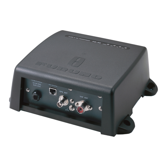
Page 13: Ais Transponder Fa-50
AIS Transponder FA-50 Mounting considerations, mounting The FA-50 can be mounted on a desktop, deck or on a bulkhead. When selecting a mounting location, keep the following points in mind: • The temperature and humidity should be moderate and stable. - Page 14 1. INSTALLATION Whip antenna for AIS More than 10 m Horizontal separation distance Cabling • Use coaxial cable type 5D-2V or the equivalent. • The cable should be kept as short as possible to minimize signal attenuation, and the maximum length is 50 meters. •...
-
Page 15: Gps Antenna
GPS Antenna Install the GPS antenna unit referring to the outline drawing at the back of this manual. When selecting a mounting location for the antenna, keep in mind the following points. • Select a location out of the radar beam. The radar beam will obstruct or prevent re- ception of the GPS satellite signal. - Page 16 1. INSTALLATION How to attach the connector N-P-8DFB for cable 8D-FB-CV Inner Sheath Outer Sheath Shield Armor Cover with heat-shrink tubing and heat. Washer 1 Clamp Clamp Gasket (reddish Aluminum Foil brown) Trim shield here. Insulator Trim aluminum tape foil here. Clamp Nut Solder through the hole.
-
Page 17: Gps/Vhf Combined Antenna
GPS/VHF Combined Antenna Install the combined antenna unit referring to the outline drawing. When selecting a mounting location for the antenna, keep in mind the following points. • Select a location out of the radar beam. The radar beam will obstruct or prevent re- ception of the GPS satellite signal. - Page 18 1. INSTALLATION Whip antenna fixture Loosen four screws. (M5x16) Antenna fixing bracket Installing distributor DB-1 The length of the cable between the distributor and transponder is 1 m so locate the distributor within 1 m from the transponder. Fix the distributor on the bulkhead, facing the cable entrance downward.
-
Page 19: Ac-Dc Power Supply (Option)
Self-tapping screw (4x30) Note: Be sure no foreign material or water enters the distributor. AC-DC Power Supply (option) When selecting a mounting location for the unit, keep the following in mind: Keep the unit out away from areas subject to water splash. Locate the unit away from exhaust pipes and vents. -
Page 20: Wiring
1. INSTALLATION Wiring Connect power source, LAN cable, VHF antenna and ground wire as shown below. GPS Antenna GPA-017/S 150M-W2VN 0.6 m RG-10U/Y, 50 m 8D-FB-CV, 30 m/50 m: Option RG-10U/Y, 20 m: Local supply COM/POWER 12-24 VDC 2.0-1.0 A RS-422 RATING*2 Switchboard breaker *1: Supply from breaker on switchboard. - Page 21 Connection of AIS viewer (FAISPC-MX) The AIS viewer may be connected to the FA-50 directly, or to both FA-50 and NavNet VX2/3D. See the figure below for connection examples. FA-50 DIRECT CONNECTION NavNet FA-50 VX2*/3D NavNet VX2/3D CONNECTION NavNet FA-50 VX2*/3D NavNet VX2/3D CONNECTION Data sentences...
-
Page 22: Setting And Adjustments
1. INSTALLATION Setting and Adjustments After installing the equipment, set up the COM port, Network and own ship's static in- formation (MMSI, ship's name, call sign, antenna position and type of ship). The FA- 50 is set up from the PC or external display. The procedure below shows how to set up from a PC. - Page 23 3. Enter URL as http://172.31.24.3 and press the Enter key. This number is the de- fault value of FA-50. 4. Click Initial Setup to show the Initial Setup screen. COM PORT setup 1. Click COM Port Setup to show the COM Port Setup screen. 2.
- Page 24 1. INSTALLATION IEC61162: Transmit and receive IEC61162 format data via COM port. (P-sen- tences are received but not transmitted. P-sentence is FURUNO’s original sen- tence.) IEC61162+P-sentence: Transmit and receive IEC61162+P sentences format data via COM port. Off: FA-50 transmits no data from COM port.
-
Page 25: Ship Static
Continuous AIS/GPS: Output AIS/GPS data continuously. Select if interfaced with FAISPC_MX. Continuous AIS/ZDA: Output AIS/time data continuously. Select if interfaced with FAISPC_MX. Continuous GPS/ZDA: Output GPS/time data continuously. Select if interfaced with FAISPC_MX. Continuous AIS/GPS/ZDA: Output AIS/GPS/time data continuously. Select if in- terfaced with FAISPC_MX. - Page 26 1. INSTALLATION 2. Enter the Login Name and Password. The Ship Static Edit screen appears. Note that the password is known by only the FURUNO dealer. 3. Enter ship's MMSI (Maritime Mobile Service Identity) in nine digits. 4. Enter ship's name, using up to 20 alphanumeric characters.
-
Page 27: Operation
OPERATION AIS Transponder FA-50 The FA-50 has no power switch. Power is fed from the ship's switchboard, and a pow- er switch on the switchboard turns the FA-50 on or off. When powered, the PWR LED (green) on the cover lights. The three other LEDs on the cover blink or light with equip- ment state. -
Page 28: Messages
2. OPERATION Messages 2.2.1 Sending a message Pre-defined messages (maximum 16 characters for each message) are stored in the Send Message screen. You can send a message among them once in a minute. 1. Click Message on the main menu. 2. -
Page 29: Confirming Receiving Messages
2. OPERATION 2.2.2 Confirming receiving messages You can confirm the received messages on the RX Log screen. Click RX Log on the Message menu. Click Detail to show the full message. To change the page, click <<Page (x/x). Flag field shows Read or “Not Read” for each message received. -
Page 30: Own Vessel Data Display
2. OPERATION Own Vessel Data Display The Own Vessel Data display shows your ship’s various data. 1. Show the main menu. 2. Click Own Vessel Data. FA-50/Own Vessel Data MMSI: Nine-digit number Ship Name: 20 characters, max Call sign: 7 characters, max. Internal/External Antenna Position: Shows GPS and external GPS antenna posi- tions. - Page 31 4. Choose a type, and then click the OK button. 5. Click the Cargo Type Edit button to show the Cargo Type screen. 6. Select a Cargo Type from the drop down list and click OK. 7. Click Region List button to show the local sea area.Clicking the Detail button shows the detailed information of the region.
- Page 32 2. OPERATION 9. Click the Group Assignment button to show the Group Assignment window. This window shows the following list when receiving a group assignment message via VHF, own ship is cruising in the area specified on the message. Assigned mode: Own ship's data is sent automatically with the designated interval in the specified area.
-
Page 33: Alarm Status
Alarm Status The alarm status log shows alarms violated. Click “Alarm Status” on the top menu to show the alarm status log. Alarm Status Indication EPFS Meaning TX malfunction (and Error LED lights.) TDMA RX1 Board trouble. TX stopped on corresponding TX channel. -
Page 34: Sensor Status
2. OPERATION Sensor Status The sensor status display provides information about sensors connected to the FA-50. 1. Show Top Menu. 2. Click Sensor Status. Internal GPS in use Heading valid Channel Management Parameters Changed Indication DGPS in use (Internal/External) GPS in use (Internal/External) SOG/COG in use (Internal/External) Heading valid Channel Management Parameters... -
Page 35: Maintenance, Troubleshooting3-1
MAINTENANCE, TROUBLESHOOTING WARNING Do not open the shield cover unless totally familiar with electrical circuits and service manual. Only qualified personnel should work inside the equipment. Maintenance Regular maintenance helps good performance. Check the items listed below monthly to keep your equipment in good working order. Item Wiring Ground... -
Page 36: Replacing The Fuse
If this happens, turn off the power to the FA-50, open the body cover and check the fuse. If the fuse has blown, find out the reason before replacing it. If it blows again after replacement, contact a FURUNO agent or dealer for advice. Part Fuse (4A) Use the proper fuse. -
Page 37: Diagnostics
Diagnostics The built-in diagnostic facility displays program version no. and TX text, then checks RAM, ROM, RX channels and GPS antenna for proper operation. 1. Open Internet Explorer and display the main menu. 2. Click Tests to show the Tests display. 3. - Page 38 3. MAINTENANCE, TROUBLESHOOTING This page is intentionally left blank.
-
Page 39: Appendix 1 Menu Tree
APPENDIX 1 MENU TREE Initial Setup Own Vessel Data Message Alarm Status Sensor Status Tests For Service (Required a password.) COM Port Setup Data Type ( IEC61162 , IEC61162+P-sentence, Off) TX Speed ( 38400 bps ) RX Speed ( Auto , Manual ( 4800 bps , 38400 bps)) Network Setup MAC Address IP Address ( 172.031.024.003 ) -
Page 40: Appendix 2 Vhf Channel Lists
APPENDIX 2 VHF CHANNEL LISTS USA mode Ch No. Frequency (MHz) 1001 1003 1005 1007 1018 1019 1020 1021 1022 1023 1024 1025 1026 1027 1028 1061 1063 1064 1065 1066 1078 1079 1080 1081 1082 1083 1084 AP-2 Ch No. 156.05 1088 2001... - Page 41 International mode Ch No. Frequency (MHz) 1001 1002 1003 1004 1005 1007 1018 1019 1020 1021 1022 1023 1024 1025 1026 1027 1028 1060 1061 1062 1063 1064 1065 1066 1078 1079 1080 1081 1082 1083 1084 1085 1086 1087 CH13, 67: operate on 1W.
-
Page 42: Appendix 3 Parts List, Locations
APPENDIX 3 PARTS LIST, LOCATIONS Parts lists F U R U N O ELECTRICAL PARTS LIST NAME PRINTED CIRCUIT BOARD MAIN&TX POWER GPS TB AP-4 Model FA-50 Unit Tranponder Blk.No. TYPE 05P0814 05P0809 05P0808A 05P0808B 24P0043 CODE NO. 001-034-470 001-034-460 001-015-620 001-015-630 005-955-290... -
Page 43: Parts Location
Parts location Transponder MAIN&TX Board 05P0814 APPENDIX 3 PARTS LIST, LOCATIONS RX1 Board RX2 Board 05P0808A 05P0808B POWER Board GPS TB 05P0809 24P0043 AP-5... -
Page 44: Appendix 4 Digital Interface
Isolation: opto coupler Input Impedance: 470 ohms Max. Voltage: ±15 V Threshold: 3 mA (In case of FURUNO device talker connection) Output drive capability Differential driver outputR=54 ohm, 1.1 V minR=60 ohm, 1.1 V minDriver short-circuit current: 250 mA max.Data transmissionData format and protocol are transmitted in serial asynchronous form in accordance with the stan-dard referenced in 2.1 of IEC 61162-1. - Page 45 Serial interface I/O circuit Input/Output Buffer RS422_TD RS422_RD 2.2kΩ NMEA_RD Sentence description Input sentences AIQ-AOIS query BBM-AIS broadcast binary message !--BBM,x,x,x,x,x.x,s--s,x*hh<CR><LF> | | | | | | | | | | | +--- 8 | | | | | +------ 7 | | | | | +--------- 6 | | | | +------------- 5...
- Page 46 APPENDIX 4 DIGITAL INTERFACE -DSC,xx,xxxxxxxxx,xx,xx,xx,x.x,xxxxxxxxxx,xx,a,a*hh<CR><LF> | | | | | | | | | | | | | | | | | | | | | | | +--------- 7 | | +----------- 6 | +-------------- 5 | +----------------- 4 +-------------------- 3 +----------------------- 2 +------------------------------ 1...
- Page 47 GBS-GNSS satellite fault direction $--GBS,hhmmss.ss,x.x,x.x,x.x,xx,x.x,x.x,x.x*hh<CR><LF> | +--------------------------- 4 +------------------------------- 3 +----------------------------------- 2 +------------------------------------------- 1 GGA-Global positioning system (GPS) fix data $--GGA,hhmmss.ss,llll.ll,a,yyyyy.yy,a,x,xx,x.x,x.x,M,x.x,M,x.x,xxxx*hh<CR><LF> +----+--------------------------------- 3 +---+--------------------------------------------- 2 +------------------------------------------------------------- 1 GLL-Geographic position-latitude/longitude $--GLL,llll.ll,a,yyyyy.yy,a,hhmmss.ss,A,a*hh<CR><LF> +------+----------------------- 2 +--+----------------------------------- 1 NOTE Positioning system Mode indicator: A = Autonomous D = Differential E = estimated(dead reckoning) M = Manual input...
- Page 48 APPENDIX 4 DIGITAL INTERFACE GNS-GNSS fix data $--GNS,hhmmss.ss,llll.ll,a,yyyyy.yy,a,c--c,xx,x.x,x.x,x.x,x.x,x.x*hh<CR><LF> +-------+--------------------------------- 3 +--+--------------------------------------------- 2 +------------------------------------------------------------- 1 HDT-Heading true OSD-Own ship data $--OSD,x.x,A,x.x,a,x.x,a,x.x,x.x,a*hh<CR><LF> | | | | | | | | | +----------- 9 | | | +-------------- 8 | | | +------------------ 7 | | +--------------------- 6 | +------------------------ 5 +--------------------------- 4...
- Page 49 RMC-Recommended minimum specific GNSS data --RMC,hhmmss.ss,A,llll.ll,a,yyyyy.yy,a,x.x,x.x,xxxxxx,x.x,a,a*hh<CR><LF> +---+---------------------------- 4 +---+---------------------------------------- 3 +--------------------------------------------------- 2 +---------------------------------------------------------- 1 NOTE Positioning system Mode indicator: A = Autonomous D = Differential E = estimated(dead reckoning) M = Manual input S = Simulator N = Data not valid SSD-AIS ship static data $--SSD,c--c,c--c,xxx,xxx,xx,xx,c, aa*hh<CR><LF>...
- Page 50 APPENDIX 4 DIGITAL INTERFACE VSD-AIS voyage static data $--VSD,x.x,x.x,x.x,c--c,hhmmss.ss,xx,xx,x.x,x.x*hh<CR><LF> +----------------------- 5 +------------------------------ 4 +----------------------------------- 3 +--------------------------------------- 2 +------------------------------------------- 1 Note: VTG-Course over ground and ground speed $--VTG,x.x,T,x.x,M,x.x,N,x.x,K,a*hh<CR><LF> | | | | | | | | | | | | | | +---+----------- 4 | | | | +--+----------------- 3 | | +--+----------------------- 2...
- Page 51 ACA-AIS channel assignment message $--ACA,x,IIII.I, a,yyyyy.y,a,IIII.I,a,yyyyy.y,a,x,xxxx,x,xxxx,x,x,x,a,x,hhmmss.s*hh<CR><LF> ACS-Channel management information source $--ACS,x,xxxxxxxxx,hhmmss.ss,xx,xx,xxxx*hh<CR><LF> ALR-Set alarm state $--ALR,hhmmss.ss,xxx,A,A,c--c*hh<CR><LF> +--------------------------------- 1 1. Time of alarm condition change, UTC 2. Local alarm number(identifier) 3. Alarm condition(A=threshold exceeded, V=not exceeded) 4. Alarm’s acknowledge state, A=acknowledged V=unacknowledged 5.
- Page 52 APPENDIX 4 DIGITAL INTERFACE TXT-Text transmission $--TXT,xx,xx,xx,c--c*hh<CR><LF> | | | | | | | +--- 5 | +--+----- 4 | | +---------- 3 | +------------- 2 +---------------- 1 VDM-AIS VHF data-link message !--VDM,x,x,x,a,s--s,x*hh<CR><LF> | | | | | | | | | +--- 7 | | | | | +----- 6...
- Page 53 SPECIFICATIONS OF CLASS B AIS TRANSPONDER GENERAL Type Class B AIS Transponder RX capacity 2250 report/minute, 1channel 4500 report/minute, 2channel RX system CSTDMA dual wave simultaneous reception Synchronous framing Indirect synchronize from external oscillator Operating mode Autonomous, Assigned, polled/interrogation response Frequency switching Automatic Prevention of abnormal TX...
- Page 54 Co-channel rejection 10 dB Adjacent channel selectivity Spurious response 70 dB Inter-modulation 65 dB Sensitivity suppression 84 dB GPS RECEIVER Receiving frequency 1575.42 MHz Tracking code C/A code Number of channel 12 channels parallel, 12 satellites Position fixing method All in view, 8-state Kalman filter Position accuracy 10 m approx., 95% of the time, (HDOP DGPS: 5m approx., 95% of the time...
- Page 55 Bearing vibration COATING COLOR GPS antenna unit Transponder IEC 60945 N9.5 N2.5 SP-3 E4442S01A...
-
Page 56: Packing Lists
GVA-100,GVA-100-T N A M E ユニット UNIT 複合空中線部 GPS/VHF COMBINED ANTENNA 工事材料 INSTALLATION MATERIALS コネクタ(N) CONNECTOR コンベックス PLASTIC BAND アンテナ取付金具 ANTENNA FIXING BRACKET ミガキ平座金 FLAT WASHER 六角ナット 1種 HEX.NUT 1.コ-ド番号末尾の[**]は、選択品の代表型式/コードを表します。 CODE NUMBER ENDING WITH "**" INDICATES THE CODE NUMBER OF REPRESENTATIVE MATERIAL. 型式/コード番号が2段の場合、下段より上段に代わる過渡期品であり、どちらかが入っています。 なお、品質は変わりません。... - Page 57 工事材料表 INSTALLATION MATERIALS 番 号 名 称 NAME ビニ-ルテープ NO360 VINYL TAPE 変換ケーブル組品 CONVERT CABLE ASSY. コネクタ CONNECTOR コネクタ(TNC-N) CONNECTOR 絶縁テープ SELF-BONDING TAPE 型式/コード番号が2段の場合、下段より上段に代わる過渡期品であり、どちらかが入っています。 なお、品質は変わりませ ん。 TWO TYPES AND CODES MAY BE LISTED FOR AN ITEM. THE LOWER PRODUCT MAY BE SHIPPED IN PLACE OF THE UPPER PRODUCT.
- Page 58 Aug.30'07 R.Esumi...
- Page 59 Mar,27'07 R.Esumi...
- Page 60 Feb.22'05...
- Page 62 Nov.28'03...
- Page 64 0.8m 0.2m...
-
Page 65: Index
INDEX AC-DC power supply ...1-9 alarm status ...2-7 COM PORT...1-13 distributor ...1-8 Fuse ...3-2 fuse ...3-2 GPS antenna ...1-5 GPS/VHF combined antenna...1-7 index term ...AP-6 IP address ...1-12 maintenance ...3-1 menu tree ...AP-1 NavNet ...1-11 NETWORK...1-14 optional supply ...1-2 own vessel data ...2-4 parts lists ...AP-4 parts location...AP-5 receiving messasge ...2-3...