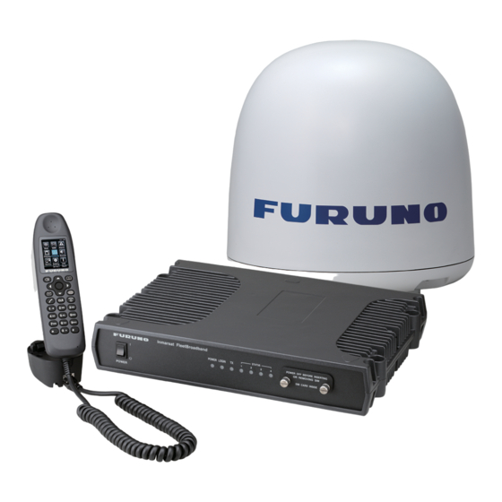
Furuno FELCOM 250 Installation Manual
Inmarsat fleetbroadband
Hide thumbs
Also See for FELCOM 250:
- Service manual (462 pages) ,
- Operator's manual (190 pages) ,
- Operator's manual (165 pages)
Table of Contents
Advertisement
Quick Links
INMARSAT FLEETBROADBAND
SAFETY INSTRUCTIONS .............................................................................................................i
SYSTEM CONFIGURATION ........................................................................................................ii
EQUIPMENT LISTS.....................................................................................................................iii
1. HOW TO INSTALL THE UNIT ................................................................................................. 1
1.1 Antenna Unit ......................................................................................................................1
1.2 Communication Unit.........................................................................................................12
1.3 IP Handset .......................................................................................................................13
1.4 Incoming Indicator (option)............................................................................................... 14
1.5 Facsimile FAX-2820 (Option)...........................................................................................16
1.6 Telephone FC755D1 (Option)..........................................................................................17
2. CONNECTIONS ..................................................................................................................... 20
2.1 Standard Connection .......................................................................................................20
2.2 Antenna Cable .................................................................................................................21
2.3 Communication Unit.........................................................................................................24
2.4 Notice for network connection..........................................................................................27
2.6 LAN Cable Fabrication .....................................................................................................30
3. SETTING AFTER INSTALLATION........................................................................................31
3.1 Preparation for Setting .....................................................................................................31
3.2 GPS Setting ..................................................................................................................... 34
3.3 Analog Port Setting .......................................................................................................... 35
3.4 Incoming Indicator Setting................................................................................................36
3.5 Serial Port Setting ............................................................................................................37
3.6 Satellite Setting ................................................................................................................38
3.7 OTA Setting......................................................................................................................39
3.8 Handset Setting................................................................................................................40
APPENDIX 1 JIS CABLE GUIDE...........................................................................................AP-1
PACKING LIST ......................................................................................................................... A-1
OUTLINE DRAWINGS.............................................................................................................. D-1
INTERCONNECTION DIAGRAM ............................................................................................. S-1
All brand and product names are trademarks, registered trademarks or service marks of their respective holders.
Installation Manual
FELCOM 250/FELCOM 500
www.furuno.co.jp
Advertisement
Table of Contents

Related Manuals for Furuno FELCOM 250


Summary of Contents for Furuno FELCOM 250
-
Page 1: Table Of Contents
INMARSAT FLEETBROADBAND FELCOM 250/FELCOM 500 SAFETY INSTRUCTIONS ...i SYSTEM CONFIGURATION ...ii EQUIPMENT LISTS...iii 1. HOW TO INSTALL THE UNIT ... 1 1.1 Antenna Unit ...1 1.2 Communication Unit...12 1.3 IP Handset ...13 1.4 Incoming Indicator (option)... 14 1.5 Facsimile FAX-2820 (Option)...16 1.6 Telephone FC755D1 (Option)...17... - Page 2 : +81-(0)798-65-4200 Printed in Japan All rights reserved. Pub. No. IME-56660-H (YOSH ) FELCOM500/250 The paper used in this manual is elemental chlorine free. ・FURUNO Authorized Distributor/Dealer A : AUG H : FEB . 18, 2011 *00017097917* *00017097917* *00017097917* *00017097917*...
-
Page 3: Safety Instructions
Only qualified personnel should work inside the equipment. Do not approach the radome closer than 1.4 m (FELCOM 500) or 0.7 m (FELCOM 250) when it is transmitting. The radome emits radio waves which can be harmful to the human body, particularly the eyes. -
Page 4: System Configuration
200-230 VAC PR-240 Solid line: Basic configuration Environmental Category Antenna unit Communication unit, IP handset, etc. Antenna unit FB-1500 (FELCOM 500) FB-1250 (FELCOM 250) LAN(4) Communication unit FB-2000 TEL(4) NMEA Normal Close RS-232C To be installed in an exposed area... -
Page 5: Equipment Lists
000-170-982-10 For FAX-2820 001-111-660-10 For FAX-2820 000-136-423-11 100 m for antenna cable 001-067-300 001-067-310 Remarks For FELCOM 500 For FELCOM 250 30 m antenna cable 50 m antenna cable 40 m antenna cable For FB-1500 For FB-1250 For FB-2000 For FB-8000... - Page 6 001-115-470-10 For FELCOM 500 EQUIPMENT LISTS Remarks Modular connector MPS588-C2 pcs for LAN cable MJ-2S, 3 m cord, lug MJ-2S, lug at both ends For analog TEL. Box type Flush mount type For FELCOM 250 antenna unit For FELCOM 500...
-
Page 7: How To Install The Unit
HOW TO INSTALL THE UNIT Do not apply paint, anti-corrosive sealant or contact spray to coating or plastic parts of the equipment. Those items contain organic solvents that can damage coating and plastic parts, especially plastic connectors. Antenna Unit General Interfering objects (especially metal objects like masts) near the antenna can, in the worst case, prevent reception or transmission. - Page 8 Locate away from passengers and crew Radio waves can be harmful to the human body. Because safe distances change by country and ship construction, there is no standard formula to calculate safe distance. However, below are general guidelines. • FELCOM 500: Personnel should not approach an area in which the radiation level is higher than 10 W/m2, i.e., within 1.40 m from the radome surface.
- Page 9 1. HOW TO INSTALL THE UNIT • FELCOM 250: Personnel should not approach an area in which the radiation level is higher than 10 W/m2, i.e., within 0.70 m from the radome surface. Construct a protective fence around the antenna unit so that personnel can not approach the antenna unit within 0.70 m.
- Page 10 Expected ice and snow Maximum wind pressure (at wind speed 56 m/s) 1. HOW TO INSTALL THE UNIT Wind Pressure (Above figure: FELCOM 500) FELCOM 500 FELCOM 250 21 kg (46 lb) ± 10% 6.5 kg ± 10% 280 N 36.3 N...
- Page 11 Minimum 20 mm (0.79") Weld a ground bolt M10x40 (same direction of the cable gland of the antenna unit) φ139.8 (φ5.50") [Antenna mast: Example] FELCOM 250 200 mm (7.87") φ (φ2.36") φ 6× Cable Entry and Drain Fixing Hole [Mounting base] Thickness: Minimum 10 mm (0.39")
- Page 12 FELCOM 500: How to install the antenna unit Carefully unpack the radome and check for damage. Antenna unit installation materials Item Silicone sealant Rubber mat Radiation warning sticker Hex bolt Hex nut Spring washer Flat washer Seal washer Procedure 1. Loosen four lifting lugs and turn them to outside at the bottom of the radome as shown in the figure on the next page.
- Page 13 1. HOW TO INSTALL THE UNIT 5. Lay the rubber mat on the mounting base and put the antenna unit on the rubber mat, keeping in mind cable gland direction (standard direction is stern). Lifting lug Turn four lifting lugs to outside.
- Page 14 9. Restore the lifting lugs to their original positions. Ground stud Silicone sealant FELCOM 250: How to install the antenna unit Carefully unpack the radome and check for damage. Run the antenna cable before installation of the antenna unit. Antenna unit installation materials...
- Page 15 1. HOW TO INSTALL THE UNIT Procedure 1. Attach the rubber mat on the bottom of the antenna unit if the mat is supplied as the installation material. 2. Connect the antenna cable to the coaxial plug on the bottom of the antenna unit. 3.
- Page 16 1. HOW TO INSTALL THE UNIT 9. Coat all bolts and nuts with silicone sealant to prevent electrolytic corrosion as shown below. Flat washer Spring washer Silicone sealant Antenna fixing bolt Silicone sealant Note: The cable entry hole (φ60) at the bottom of the antenna functions as ventilation hole, allowing trapped moisture to escape the dome.
- Page 17 3. Insert the mounting pole SP-SAC-1031 through the U-bolts of the fixing plate and fasten the U-bolts. 4. Put the FELCOM 250 antenna unit on the mounting pole and fix it with nuts (see previous page). Antenna unit...
-
Page 18: Communication Unit
Communication Unit Select a location for the communication unit (CU) by following the information shown below. • The unit is not waterproof. Keep the unit away from water splash. • Keep the unit away from direct sunlight. • The temperature and humidity must meet the requirements shown in the equipment specifica- tions. -
Page 19: Ip Handset
1. HOW TO INSTALL THE UNIT IP Handset The IP handset functions as a display and it may also be used for normal voice communication. The units (max 26 units) may be installed anywhere onboard the vessel. The IP handset is pro- vided with a cradle. -
Page 20: Incoming Indicator (Option)
Incoming Indicator (option) Select a location for the incoming indicator by following the information shown below. • Keep the unit away from water splash. • Keep the unit away from direct sunlight. • Set the unit away from the exhaust pipes and vents. •... - Page 21 1. HOW TO INSTALL THE UNIT 4. Fix the case with four M4x8 screws (supplied) to the flush mount plate. 5. Pass the cable from the CU through the bottom of the case. 6. Connect the cable to the port on the lid. 7.
-
Page 22: Facsimile Fax-2820 (Option)
Facsimile FAX-2820 (Option) Note: The hooks supplied are not used in the installation. 1. Lay the facsimile on the top of the mounting plate. 2. Align right side and rear with the projection on the mounting plate. 3. Fasten fixing plates (left, right) to the facsimile with six M4x15 pan head screws. Fixing plate (left) Mounting plate φ6 Fixing hole... -
Page 23: Telephone Fc755D1 (Option)
1. HOW TO INSTALL THE UNIT 4. Attach the compass safe distance label at the location shown below. How to change modem settings 1. Press [Menu/set], [*], [2], [8], [6] and [4] keys in this sequence to enter the maintenance mode. The fax machine beeps for approximately one second and displays "MAINTENANCE"... - Page 24 How to mount The mounting dimensions are shown in the outline drawing at the back of this manual. Determine the mounting loca- tion, leaving sufficient space around the unit, and then fix the mounting base to the mounting location. The mounting base is different for bulkhead and desk- top mounts, however the mounting pro- cedure is the same for all.
- Page 25 1. HOW TO INSTALL THE UNIT 1) Remove the plastic sheet and recording sheet. 2) Set #1 DIP switch to ON (PB side). Line type 3) Reattach the plastic sheet and recording sheet. Remove plastic sheet and recording sheet. Side tone Bell off PB S Set #1 to ON (PB).
-
Page 26: Connections
Run and connect cables, refering to the figure below and the interconnection diagram (page S-1). FELCOM 500 Antenna unit FB-1500 L-BAND OUT IP Handset FB-8000 Incoming Indicator FB-3000 INCOMING INDICATOR VOLUME Inmarsat FleetBroadband FELCOM 250 Antenna unit FB-1250 RS-232C NMEA ALARM Copper strap 05-003- 0031-0 Bolt or weld to ship’ hull. -
Page 27: Antenna Cable
(local supply). Fix the cable to the mast with a cable tie (local supply). [FELCOM 500] See the figure below. Cable tie Inside: Self-adhesive tape Outside: Vinyl tape Waterprooting the coaxial connector [FELCOM 250] Mast Cable tie (Weatherproofed) Mouting Cable tie... - Page 28 How to attach the antenna cable connector N-P-8DFB-CF Attach the coaxial plug (supplied) to the other end of the coaxial cable to connect to the CU as follows. Outer Sheath Armor Inner Sheath Cover with heat-shrink tubing and heat. Clamp Gasket (reddish brown)
- Page 29 2. CONNECTIONS How to attach the antenna cable connector N-SP-12DSFA-CF If the optional coaxial cable 12D-SFA-CV (100 m) is used, attach the optional coaxial plug N-SP- 12DSFA-CF as follows. Dimensions in millimeters. Outer Sheath Armor Inner Sheath Clamp Nut Gasket Washer Clamp Nut Solder through...
-
Page 30: Communication Unit
Communication Unit Telephone FC755D1 and Facsimile FAX-2820 Connect the cable from the telephone or facsimile to TEL1, 2, 3 or 4 port of the communication unit. The modular connector can be connected directly to the TEL1 or TEL2 as shown in the fig- ure below. - Page 31 2. CONNECTIONS TTYCS-1 Cable fabrication Approx. 40 Cores Inner φ3 Braided shield connnector Push Twist Wire NMEA signal, External alarm Communication unit FB-2000 NMEA Signal TD-A TD-B RD-A RD-B See the figure on previous page for how to fix FMC connector.
- Page 32 Cable fixture To connect the LAN and TEL lines, attach the cable fixture (supplied) to the rear panel of the com- munication unit. Then insert the connectors to each port. Fasten each cable with a cable tie (sup- plied) to the cable fixture. Connect the braided shield wire of each cable to the ground terminal. Cable fixture Fasten cable to this post of cable fixture with a...
-
Page 33: Notice For Network Connection
2. CONNECTIONS Notice for network connection With a hub(s), FELCOM500/FELCOM250 can establish a network configuration. If the hub(s) is connected in loop form, the FELCOM500/FELCOM250 may not function normally. Never connect as follows: Communication unit FB-2000 [Hub 1 set] Note: If you install a switching hub that does not have an automatic function to distinguish straight/ cross (MDI/MDI-X) connections, you will need to select a proper cable: •... -
Page 34: Desktop Installation Of Communication Unit To Comply With Ipx2 (Dripping) Standard
Desktop Installation of Communication Unit to- comply with IPX2 (dripping) standard How to inset the grommet Be sure to install the Communication Unit to a desktop to protect from dripping. After installing, affix the grommets over the mounting screws. How to install the connector cover After connecting the cables, perform the following to affix the connector cover. - Page 35 2. CONNECTIONS 3. With the connector cover rail in the slot, raise the connector cover in the direction of the arrow as shown below. 4. Push the connector cover in towards the triangle mark on the center top of the Communication Unit to affix.
-
Page 36: Lan Cable Fabrication
LAN Cable Fabrication Fabricate an optional LAN cable (FR-FTPC-CY 10, 20, 30, 50 or 100 m) as follows. Cut armor and outer vinyl sheath as shown below and then connect the modular connector MPS588-C (option) to both ends. Expose inner vinyl sheath. approx. -
Page 37: Setting After Installation
1. Turn on the PC and insert the CD-ROM (supplied with accessories) in the PC. 2. Open the CD-ROM and copy "FELCOM_FB" shortcut icon to the desktop of the PC. This shortcut icon accesses the FELCOM 500/FELCOM 250 (IP address 192.168.1.1) through the Internet Explorer. - Page 38 The browser starts and the main menu of the Web software in the FELCOM 250/500 opens. For FELCOM250, “FELCOM250” is indicated. 7. Click the Administrator Login button on upper right hand side on the screen.The Login win- dow opens. 8. Key in username "Admin" and password "01234567"(default value).The administrator can change the password in another menu.
- Page 39 3. SETTING AFTER INSTALLATION 10. Click Settings on the menu bar. The sub menu appears on left side and current setting appears in the Information window on right side. Basic settings 11. Click Basic settings on the sub menu. The sub menu of the Basic settings appears Basic settings Basic settings sub menu Use these sub menus to set the basic settings, following the procdeures on the next several...
-
Page 40: Gps Setting
GPS Setting 1. Click GPS on the Basic settings sub menu. 2. If an external GPS is connected to the NMEA port on the communication unit, set the baud rate to 4800 bps or 38400 bps according to the GPS connected. 3. -
Page 41: Analog Port Setting
3. SETTING AFTER INSTALLATION Analog Port Setting Set for analog telephones/faxes that are connected to the TEL ports as follows. 1. Click Analog ports on the Basic settings sub menu. Analog port 2. In the Type box, select the equipment that is connected to the TEL port. There are four TEL ports (TEL 1 to TEL 4), TEL 1 is analog port 1 in the table. -
Page 42: Incoming Indicator Setting
Incoming Indicator Setting If the optional Incoming Indicator is connected, set it as follows. 1. Click Incoming Indicator in the Basic settings sub menu. Incoming Indicator 2. Select the ringing pattern of the incoming indicator in the "Ringing pattern of each service", between same pattern and Different pattern. -
Page 43: Serial Port Setting
3. SETTING AFTER INSTALLATION Serial Port Setting Set for the equipment that is connected to the RS-232C port. 1. Click Serial port in the Basic settings sub menu. Serial port 2. Select a baud rate from the Baud rate drop-down list. The selections are 9600, 19200, 38400, 57600 and 115200 bps. -
Page 44: Satellite Setting
Satellite Setting The three satellites are named APAC (Asia-pacific), EMEA (Europe-Middle east-Africa) and AMER (America). To change satellite name, do as follows. 1. Click Satellite in the Basic settings sub menu. Satellite 2. Put the cursor in the Name box and enter the name of the satellite (max. 10 characters). 3. -
Page 45: Ota Setting
3. SETTING AFTER INSTALLATION OTA Setting OTA stands for Over The Air. The OTA function permits remote management of files in the SIM card. 1. Click OTA in the Basic setting sub menu. 2. To enable the OTA, click the Enabled radio button. To disable the OTA, click the Disabled ra- dio button. -
Page 46: Handset Setting
Handset Setting To use the IP handset, set the Web software and the IP handset as follows. Web software setting 1. Click Settings in the menu bar. 2. Click PBX Settings in the Settings sub menu at the left side of the screen. 3. - Page 47 3. SETTING AFTER INSTALLATION Setting in the IP handset 1. Push the Enter key at the idle screen to show the main menu. 2. Push 6 to select the Settings icon and then push the Enter key to show the Settings menu. 3.
- Page 48 5. With the Phone number box highlighted in blue, push the Enter key to show the phone num- ber input screen. 6. Enter the extension number that is registered in the Web software and push the Enter key. If something has been registered, push the CLR key to erase it. 7.
- Page 49 3. SETTING AFTER INSTALLATION These handsets can be used for communication. However, the following screen does not update automatically. Press the Reload button of the browser to refresh the screen.
-
Page 50: Appendix 1 Jis Cable Guide
1mm Multi core 0.75mm twisted pair communications (1Q = quad cable) 4. Armor Type Steel DPYCYS - 1.5 Designation type The following reference table lists gives the measurements of JIS cables commonly used with Furuno products: Core Type Area Diameter DPYC-1.5 1.5mm... - Page 57 8/Mar/10 R.Esumi...
- Page 58 11/Dec/09 R.Esumi...
- Page 62 18/Feb/09 R.Esumi...
- Page 65 T.Matsuguchi Feb.15'06...