Furuno 1715 Operator's Manual
Furuno marine radar operator's manual
Hide thumbs
Also See for 1715:
- Operator's manual (48 pages) ,
- Service manual (44 pages) ,
- User manual (33 pages)
Table of Contents
Advertisement
Quick Links
Advertisement
Table of Contents
Troubleshooting

Related Manuals for Furuno 1715


Summary of Contents for Furuno 1715
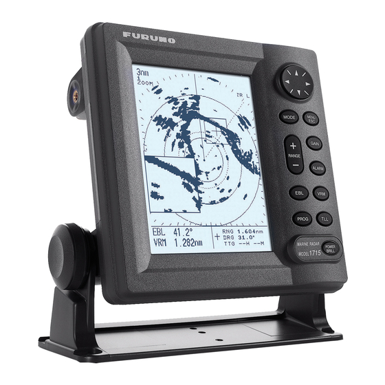
- Page 1 MARINE RADAR MODEL 1715...
- Page 2 9-52 Ashihara-cho, 9-52 Ashihara-cho, Nishinomiya, Japan Nishinomiya, Japan Telephone : Telephone : 0798-65-2111 0798-65-2111 Telefax : Telefax : 0798-65-4200 0798-65-4200 Printed in Japan Printed in Japan All rights reserved. All rights reserved. PUB.No. OME-35140 PUB.No. OME-35140 ) ) MODEL1715 MODEL1715 Your Local Agent/Dealer Your Local Agent/Dealer FIRST EDITION :...
-
Page 3: Table Of Contents
TABLE OF CONTENTS SAFETY INSTRUCTIONS... ii FOREWORD... iii SYSTEM CONFIGURATION... iv EQUIPMENT LISTS... v 1. OPERATION ... 1 1.1 Controls ... 1 1.2 Indications ... 2 1.3 Turning Power On/Off ... 3 1.4 Transmitting, Standby... 3 1.5 Adjusting Display Contrast, Brilliance ... 4 1.6 Choosing the Range ... -
Page 4: Safety Instructions
WARNING LABEL A warning label is attached to the equipment. Do not remove the label. If the label is missing or damaged, contact a FURUNO agent or dealer about replacement. Name: Warning Label (1) WARNING Type: 86-003-1011-1 To avoid electrical shock, do not Code No.: 100-236-231... -
Page 5: Foreword
The main features of the MODEL 1715 are • Daylight viewing radar specially designed for small craft and sailing yachts. -
Page 6: System Configuration
SYSTEM CONFIGURATION DISPLAY UNIT RDP-142 RECTIFIER PR-62 SHIP'S MAINS 12-24 VDC SHIP'S MAINS 115/230 VAC, φ , 50/60 Hz ANTENNA UNIT RSB-0095 GPS RECEIVER GP-310B/320B MENU MODE WIND INDICATOR, GAIN SPEED INDICATOR RANGE ALARM NAVIGATOR PROG or ECHO SOUNDER POWER BRILL (NMEA 0183) EXTERNAL... -
Page 7: Equipment Lists
EQUIPMENT LISTS Standard supply Name Type Antenna Unit RSB-0095 Display Unit RDP-142 CP03-25301 CP03-24910 Installation CP03-24920 Materials* CP03-24930 CP03-25101 Spare Parts* SP03-09800 *: See packing list at end of manual. Option Name Buzzer Assy. XH3-BZ-L970 Cable Assy. MJ-A7SPF0007-050 Cable Assy. MJ-A15A7F0004-005 Cable Assy. -
Page 8: Operation
1. OPERATION 1.1 Controls How to remove the hard cover Place your thumbs at the center of the cover, and then lift the cover while pressing it with your thumbs. Cursor Pad Chooses menu items; adjusts VRM, EBL and cursor. Chooses display mode. -
Page 9: Indications
1.2 Indications Range Range ring interval ZOOM WATCH Zoom Watchman Guard zone Cursor Range, XTE (Cross-track error) EBL/VRM Box EBL bearing VRM range Appropriate sensors required to display nav data. About the LCD The high quality LCD displays better than 99.99% of its picture elements. The remaining 0.01% may drop out or light, however this is not an indication of malfunction;... -
Page 10: Turning Power On/Off
NG appears, try to press any key except the [POWER/BRILL] key to start operation. However, the equipment may not work properly. Contact your dealer for advice. 7" LCD MARINE RADAR FURUNO ELECTRIC CO., LTD. ROM : OK RAM : OK Program No: 0359199-XX.XX XX.XX = Program version no. -
Page 11: Adjusting Display Contrast, Brilliance
1.5 Adjusting Display Contrast, Brilliance 1. With the power turned on, press the [POWER/BRILL] key momentarily to show the brilliance/contrast adjustment window. BRILL/CONTRAST CONT: BRILL: [MODE]: TX/ST-BY [MENU/ESC] : Exit. Brilliance/contrast adjustment window 2. Press ◄ or ► to adjust contrast. 3. -
Page 12: Suppressing Sea Clutter
1. OPERATION 2. Press ▲ or ▼ to choose AUTO or MANU as appropriate. Automatic gain adjustment 1) Press ► to open the automatic gain options window. ROUGH MODERATE CALM Automatic gain options 2) Press ▲ or ▼ to choose ROUGH, MODERATE or CALM depending on sea conditions. -
Page 13: Suppressing Rain Clutter
Manual A/C SEA adjustment While observing the screen and the A/C SEA tuning bar, press ◄ or ► to adjust the A/C SEA. The setting range is 0-100. 4. Press the [MENU/ESC] key to finish. 1.9 Suppressing Rain Clutter The vertical beamwidth of the antenna is designed to see surface targets even when the ship is rolling. -
Page 14: Measuring The Bearing
1. OPERATION 1.11 Measuring the Bearing The bearing to a target can be measured with the cursor and the EBL (Electronic Bearing Line). Measuring bearing with the cursor Operate the cursor pad to place the cursor on the inside edge of the target. Read the bearing to the target at the bottom right corner. -
Page 15: Zoom
1.13 Zoom The zoom feature allows you to double the size of a selected area. If zoom is activated when nav data is displayed, the nav data is automatically erased. 1. Use the cursor pad to place the cursor where you want to zoom. 2. -
Page 16: Heading Line
1. OPERATION User menu description Item Description Rejects radar interference. REJECTION ECHO Stretches echoes in range STRETCH direction or range and bearing direction. Suppresses long-range rain clutter. NOISE Rejects noise. REJECTION WATCHMAN Periodically checks for targets TIME in guard zone. Chooses echo and background tones. -
Page 17: Noise Rejector
1.17 Noise Rejector The noise rejector suppresses white noise, which appears on the screen as many dots scattered randomly over the display. 1. Press the [MENU/ESC] key to open the User menu. 2. Press ▲ or ▼ to choose NOISE REJECTION from page 1. -
Page 18: Guard Alarm
1. OPERATION 1.20 Guard Alarm The guard alarm allows the operator to set the desired range and bearing for a guard zone. When ships, islands, landmasses, etc. violate the guard zone, audio and visual alarms are released to call your attention. The alarms will be released for targets entering or exiting the zone depending on the presence or absence of targets in the zone... -
Page 19: Watchman
1.21 Watchman The radar "wakes up" at specified time intervals (5, 10, or 20 minutes) and operates for 10 scans, the start of which is announced by releasing the audio alarm. If change is found in the guard zone from the previous 10 scans, the audio alarm sounds and the radar resumes normal operation, canceling the watchman mode. -
Page 20: Hue
1. OPERATION 1.24 Hue The default hue setting (DAY) displays echoes in tones of gray on a white background, which is most suitable for daytime viewing. For nighttime viewing you may reverse this arrangement. 1. Press the [MENU/ESC] key to open the User menu. -
Page 21: Turning Navigation Data On/Off
1.28 Turning Navigation Data On/Off Navigation data appears on the bottom half of the screen as in the illustration below. You may turn the navigation data display on or off as shown below. Note: When the nav data is turned on with shift or zoom active, zoom or shift is cancelled. - Page 22 1. OPERATION GRAPHIC DISPLAYS Digital XTE 0.25 Analog XTE (Bar moves right or left according to amount and direction of XTE) XTE (Cross-Track Error) GRAPHIC Speed 17.2 SPEED GRAPHIC Wind APP* 120° 10.3 Speed WIND GRAPHIC Waypoint 03 Destination Rng 0.19nm Brg 321°...
-
Page 23: System Menu
1.30 System Menu The System menu mainly contains items which once set do not require frequent adjustment. You may display this menu by choosing “SYSTEM MENU” from page 3 of the User menu and then pressing ►. PAGE 1 SYSTEM MENU LANGUAGE English RANGE UNIT... - Page 24 1. OPERATION Page 2 of system menu EBL REFERENCE: The EBL readout may be chosen from relative (relative to own ship’s heading) or true (referenced to the North). Heading data required for true bearing. Note: If no bearing data is input, course data from the GPS navigator is used.
-
Page 25: Maintenance, Troubleshooting
2. MAINTENANCE, TROUBLESHOOTING 2.1 Maintenance Regular maintenance is important for good performance. A maintenance program should be established and should at least include the items listed in the table below. Period Item Fixing bolts for antenna unit Antenna unit cleanliness Antenna unit cover 3 to 6... -
Page 26: Replacing The Fuse
2.2 Replacing the Fuse The fuse (5 A) in the power cable protects the equipment against reverse polarity of the ship’s mains, overcurrent, and equipment fault. If the fuse blows, find the cause before replacing it. Use the proper fuse. Use of a wrong fuse may cause serious damage to the equipment and void the warranty. -
Page 27: Diagnostics
NMEA ° Body: 39 GPS (XXXXXXX-XX.XX): OK* Program No. 0359199-**.** Push [MENU] 3 times to exit. * Program no. of FURUNO BlackBox GPS **.** = Program version no. Diagnostic test results Interpreting display unit test results Item ROM, OK: Normal... -
Page 28: Test Pattern
When the synchro belt has worn out, the sweep is not synchronized with antenna rotation, which results in an abnormal picture. When you suspect that the synchro belt has worn out, contact a FURUNO agent or dealer about replacement. (Type: 40 S2M 266UG, Code No: 000-808-743) FOUR-TONE... -
Page 29: Installation
3. INSTALLATION 3.1 Antenna Unit Installation Mounting considerations When choosing a mounting location for the antenna unit, keep in mind the following points: • Install the antenna unit on the hardtop, radar arch or on a mast on an appropriate platform. - Page 30 Flat washer Spring Apply silicone washer Hex bolt sealant. (M10 x 25 or M10 x 20) Platform thickness Bolt to use 5 mm or under: M10x20 5-10mm: M10x25 over 10 mm: locally supplied bolts How to fasten the antenna base to platform 4.
- Page 31 3. INSTALLATION 10. Connect the 9-pin connector of the antenna cable to J801. See the illustration on the previous page for location. 11. Refasten the shield plate with 10 screws. Be sure not to pinch the cable from the rotation detector with the shield plate. 12.
-
Page 32: Display Unit Installation
3.2 Display Unit Installation Mounting considerations When choosing a mounting location for the display unit, keep in mind the following points: • Keep the display unit out of direct sunlight. • The temperature and humidity should be moderate and stable. •... -
Page 33: Adjustments
Note: This procedure requires making a hole in the display unit, which can affect watertightness. FURUNO cannot guarantee watertight integrity after this modification is made. 1. Detach the rear panel and place it out side up on a workbench. - Page 34 1. Turn on the power while pressing and holding down the [MENU/ESC] key. Continue pressing the [MENU/ESC] key until the Installation menu appears. INSTALLATION MENU SIMULATION TEST... LCD PATTERN... MEMORY CLEAR NMEA PORT : IN/OUT NMEA OUTPUT : OFF GPS WASS : OFF GO TO RADAR SETUP...
- Page 35 3. INSTALLATION Timing adjustment Sweep timing differs with respect to the length of the antenna cable. Adjust sweep timing to prevent pushing or pulling of the target as illustrated below and placement of targets at incorrect ranges. Target pushed Correct inward Improper and correct sweep timings 1.
-
Page 36: Magnetron Heater Voltage
3.5 Magnetron Heater Voltage Magnetron heater voltage is formed at the MD Board of the antenna unit and is preadjusted at the factory. Therefore, no adjustment is required. However, verify the voltage as below. WARNING ELECTRICAL SHOCK HAZARD Do not open the equipment. DO NOT attempt the procedure below unless totally familiar with electrical... -
Page 37: Menu Tree
MENU TREE MENU/ESC INT REJECTION (OFF, LOW , MEDIUM, HIGH) ECHO STRETCH ( OFF , LOW, HIGH) FTC ( OFF , ON) NOISE REJECTION (OFF, LOW , HIGH) WATCHMAN TIME ( OFF , 5, 10, 20 min) HUE ( DAY , NIGHT) PANEL DIMMER (OFF, LOW, MEDIUM, HIGH ) HDG LINE OFF (Temporarily turns off heading line.) ECHO TRAIL ( OFF , 30 s;... -
Page 38: Specifications
SPECIFICATIONS 1. GENERAL Indication System Range, Pulselength (PL) & Pulse Repetition Rate (PRR) Range (nm) Pulse Length Pulse Repetition Rate 3000 Hz nominal Range Resolution Bearing Discrimination Minimum Range Bearing Accuracy Range Ring Accuracy 2.ANTENNA UNIT Radiator Polarization Antenna Rotation Speed 24/31/41 rpm nominal (auto-select according to range) Radiator Length Horizontal Beamwidth Vertical Beamwidth... - Page 39 Markers Alphanumeric Indications Range, Range Ring Interval, Display Mode (HU), Input Sentences Output Sentences 5. ENVIRONMENTAL CONDITIONS Ambient Temperature Relative Humidity Waterproofing Bearing Vibration 6. POWER SUPPLY 7. COATING COLOR Display Unit Scanner Unit 8. COMPASS SAFE DISTANCE Display Unit Scanner Unit Heading Line, Bearing Scale, Range Rings, Variable Range Marker (VRM), Electronic Bearing Line (EBL),...