
Related Manuals for Ferris ISZKAV23/52


Summary of Contents for Ferris ISZKAV23/52
- Page 1 Ferris Industries 5375 North Main Street Munnsville, NY 13409 800-933-6175 OPERATOR’S MANUAL Zero-Turn Riding Mower Models: ISZKAV23/52 ISZKAV23/61 Beginning Serial No: 2269 22422 3/2000 F-ISZ-OWN-00...
-
Page 3: Table Of Contents
Servicing the Mower Blades ...18 Engine exhaust from this product contains chemicals known, in certain quantities, to cause cancer, birth defects, or other reproductive harm. © Copyright 2000 Ferris Industries All Rights Reserved. Printed in USA. F-ISZ-OWN-00 Troubleshooting, Adjustments & Service ...19 Troubleshooting the Tractor ...19... -
Page 4: Identification Numbers
Identification Numbers When contacting your Authorized Dealer for replacement parts, service, or information YOU MUST HAVE THESE NUMBERS. XXXXXXX XXXXXXX IDENTIFICATION NUMBERS Record your model name/number, unit and mower deck manufacturer numbers and engine serial number in the space provided for easy reference. •... -
Page 5: Safety Rules & Information
Read these safety rules and follow them closely. Failure to obey these rules could result in loss of con- trol of unit, severe personal injury or death to you, or bystanders, or damage to property or equipment. This mowing deck is capable of amputating hands and feet and throwing objects. The triangle in text signifies important cautions or warnings which must be followed. -
Page 6: Safety Rules & Information
Safety Rules & Information CHILDREN Tragic accidents can occur if the operator is not alert to the presence of children. Children are often attracted to the unit and the mowing activity. Never assume that chil- dren will remain where you last saw them. •... -
Page 7: Safety Decals
SAFETY DECALS This unit has been designed and manufactured to pro- vide you with the safety and reliability you would expect from an industry leader in outdoor power equipment manufacturing. Although reading this manual and the safety instructions it contains will provide you with the necessary basic knowledge to operate this equipment safely and effec- tively, we have placed several safety labels on the unit to remind you of this important information while you are... -
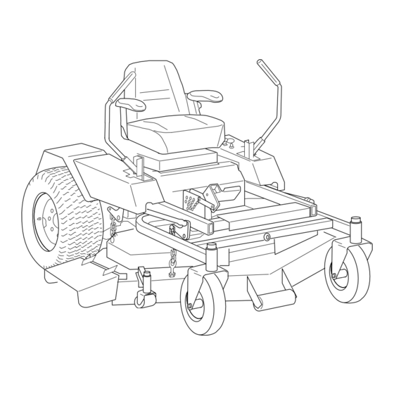
Page 8: Features & Controls
Features & Controls of the Zero Turn Rider A. Ground Speed Control Levers These levers control the ground speed of the rider. The left lever controls the left rear drive wheel and the right controls the right rear drive wheel. Moving a lever forward increases the FORWARD speed of the associated wheel, and pulling back on a lever increases the REVERSE speed. -
Page 9: Safety Interlock System
D. Parking Brake Handle The parking brake is applied by pulling UP on the park- ing brake handle until it locks over-center. To release the parking brake, push the handle DOWN. E. PTO (Power Take Off) Switch The PTO switch engages and disengages the mower. Pull UP on the switch to engage, and push DOWN to disengage. -
Page 10: Operating The Tractor
Operating the Zero Turn Rider GENERAL OPERATING SAFETY Before first time operation: • Be sure to read all information in the Safety and Operation sections before attempting to operate this tractor and mower. • Become familiar with all of the controls and how to stop the unit. -
Page 11: Starting The Engine
WARNING If you do not understand how a specific control functions, or have not yet thoroughly read the FEATURES & CONTROLS section, do so now. Do NOT attempt to operate the tractor without first becoming familiar with the location and function of ALL controls. -
Page 12: Zero Turn Driving Practice
Operating the Zero Turn Rider ZERO TURN DRIVING PRACTICE The lever controls of the Zero Turn rider are responsive, and learning to gain a smooth and efficient control of the rider’s forward, reverse, and turning movements will take some practice. Spending some time going through the maneuvers shown and becoming familiar with how the unit acceler- ates, travels, and steers —... -
Page 13: Advanced Driving
Practice Turning Around a Corner While traveling forward allow one handle to gradually return back toward neutral. Repeat several times. NOTE: To prevent pivoting directly on the tire tread, it is best to keep both wheels going at least slightly forward. Executing Turns Figure 6. -
Page 14: Storage
Operating the Zero Turn Rider STORAGE Temporary Storage (30 Days Or Less) Remember, the fuel tank will still contain some gasoline, so never store the unit indoors or in any other area where fuel vapor could travel to any ignition source. Fuel vapor is also toxic if inhaled, so never store the unit in any structure used for human or animal habitation. - Page 15 Notes...
-
Page 16: Regular Maintenance
Regular Maintenance MAINTENANCE SCHEDULE & PROCEDURES The following schedule should be followed for normal care of your rider and mower. You will need to keep a record of your operating time. Determining operating time is easily accomplished by observing the hour meter. S S A A F F E E T T Y Y I I T T E E M M S S Check Safety Interlock System Check Rider Brakes... -
Page 17: Checking/Adding Fuel
CHECKING / ADDING FUEL To add fuel: 1. Remove the fuel cap (see A, Figure 2). 2. Fill the tank. Do not overfill. Leave approximately 1” of room in the tank for fuel expansion. Refer to your engine manu- al for specific fuel recommendations. 3. -
Page 18: Lubrication
Regular Maintenance LUBRICATION Lubricate the unit at the locations shown in Figures 11 through 13 as well as the following lubrication points. Grease: • front caster wheel axles • motion control pivots • suspension a-arms • rear deck mounts • deck lift pivots •... -
Page 19: Battery Maintenance
BATTERY MAINTENANCE Checking the Battery Fluid 1. Raise the seat plate to access battery. 2. Remove the rubber strap and battery box cover. 3. Remove the battery filler cap (A, Figure 14). Fluid must be even with the split ring full mark. If not, add distilled water. -
Page 20: Servicing The Mower Blades
Regular Maintenance SERVICING THE MOWER BLADES 1. Blades should be sharp and free of nicks and dents. If not, sharpen blades as described in following steps. 2. To remove blade for sharpening, use a wood block to hold blade while removing the blade mounting bolt (Figure 15). -
Page 21: Troubleshooting Adjustments & Service
Troubleshooting Adjustments & Service... -
Page 22: Troubleshooting The Mower
Troubleshooting, Adjustment & Service Rider Troubleshooting Continued. PROBLEM Engine runs, but rider will not drive. Rider drive belt slips. Brake will not hold. Rider steers or handles poorly. TROUBLESHOOTING THE MOWER PROBLEM Mower will not raise. Mower cut is uneven. Mower cut is rough looking. -
Page 23: Seat Adjustment
SEAT ADJUSTMENT See Figure 18. The seat can be adjusted forward and back. Move the lever forward, position the seat as desired, and release the lever to lock the seat into posi- tion. GROUND SPEED CONTROL LEVER ADJUSTMENT The control levers can be adjusted in two ways. The alignment of the control levers can be adjusted along with the placement of the levers (how close the ends are to one another) can be adjusted. -
Page 24: Parking Brake Adjustment
Troubleshooting, Adjustment & Service PARKING BRAKE ADJUSTMENT 1. Disengage the PTO, stop the engine, block the front wheels, remove the ignition key, and engage the parking brake. 2. Remove both control covers. 3. Locate the upper brake spring (A, Figure 21). 4. -
Page 25: Pto Clutch Adjustment
PTO CLUTCH ADJUSTMENT Check the PTO clutch adjustment after the initial 50 hour break-in period and then after every 250 hours of operation. Also perform the following procedure if the clutch is slipping or will not engage, or if a new clutch has been installed. -
Page 26: Neutral Adjustment
Troubleshooting, Adjustment & Service NEUTRAL ADJUSTMENT If the tractor “creeps” while the ground speed control levers are locked in NEUTRAL, than it may be neces- sary to adjust the control linkage. NOTE: Perform this adjustment on a hard, level surface such as a concrete floor. -
Page 27: Cutting Height Adjustment
CUTTING HEIGHT ADJUSTMENT WARNING Before checking mower, shut off PTO and engine. Allow all moving parts to stop. Remove ignition key, then disconnect the spark plug wire and fasten it away from the spark plug. The cutting height adjustment pin (A, Figure 28) controls the mower cutting height. -
Page 28: Mower Belt Replacement
Troubleshooting, Adjustment & Service MOWER BELT REPLACEMENT To avoid damaging belts, DO NOT PRY BELTS OVER PULLEYS. 1. Park the tractor on a smooth, level surface such as a concrete floor. Disengage the PTO, engage the parking brake, turn off the engine, and remove the ignition key. -
Page 29: Battery Service
BATTERY SERVICE WARNING Keep open flames and sparks away from the battery; the gasses coming from it are highly explosive. Ventilate the battery well during charging. Checking Battery Voltage A voltmeter can be used to determine condition of bat- tery. When engine is off, the voltmeter shows battery voltage, which should be 12 volts. - Page 30 Troubleshooting, Adjustment & Service THIS HOOK-UP FOR NEGATIVE GROUND VEHICLES Starter Switch Starting Vehicle Battery To Ground MAKE CERTAIN VEHICLES DO NOT TOUCH Figure 32. Jump Starting WARNING Any procedure other than the preceding could result in: (1) personal injury caused by electrolyte squirting out the battery vents, (2) personal injury or property damage due to battery explosion,...
- Page 31 Notes...