Carrier SEER 48ES Installation Instructions Manual
13 seer single-packaged air conditioner and gas furnace system with puron (r-410a) refrigerant single and three phase
Hide thumbs
Also See for SEER 48ES:
- Owner's information manual (10 pages) ,
- Installation instructions manual (30 pages)
Table of Contents
Advertisement
48ES
Comfort t 13 SEER Single ---Packaged Air Conditioner
and Gas Furnace System with Puron® (R ---410A) Refrigerant
Single and Three Phase
Sizes 024---060
NOTE:
Read the entire instruction manual before starting the
installation.
NOTE:
Installer: Make sure the Owner's Manual and Service
Instructions are left with the unit after installation.
TABLE OF CONTENTS
. . . . . . . . . . . . . . . . . . . . . . . . . . . . . . . . . . .
. . . . . . . . . . . . . . . . . . . . . . . . . . . . . . . . . .
. . . . . . . . . . . . . . . . . . . . . . . . . . . . . . . . . . . .
. . . . . . . . . . . . . . . . . . . . . . . . . . . . . . . . .
. . . . . . . . . . . . . . . . . . . . . . . . . . . . . . .
. . . . . . . . . . . . . . . . . . . . . . . . . . . . . . . . . . . . . .
. . . . . . . . . . . . . . . . . . . . . . . . . . . . . . . . . . . . .
. . . . . . . . . . . . . . . . . . . . . . . . . . . . . . . . . .
. . . . . . . . . . . . . . . . . . . . . . . . . . . .
. . . . . . . . . . . . . . . . . . . . . . . . . . . . . . . . .
. . . . . . . . . . . . . . . . . . . . . . . . . . . . . . . . .
. . . . . . . . . . . . . . . . . . . . . . . . . . . . . . . . . . . . . .
. . . . . . . . . . . . . . . . . . . . . . . . . . . .
. . . . . . . . . . . . . . . . . . . . . . . . . . . . . . . . . .
. . . . . . . . . . . . . . . . . . . . . . . . . . . . . . . . . . .
. . . . . . . . . . . . . . . . . . . . . . . . . . . . . . . . . .
. . . . . . . . . . . . . . . . . . . . . . . . . . . .
. . . . . . . . . . . . . . . . . . . . . . . . . . . . . . . . . . . . .
. . . . . . . . . . . . . . . . . . . . . . . . . . . . .
. . . . . . . . . . . . . . . . . . . . . . . . . . .
. . . . . . . . . . . . . . . . . . . . . . . . . . . . . . . .
. . . . . . . . . . . . . . . . . . . . . . . . . . . . . . . . . . . . .
. . . . . . . . . . . . . . . . . . . . . . . . . . .
. . . . . . . . . . . . . . . . . . . . . . . . . . . . . . . .
. . . . . . . . . . . . . . . . . . . . . . . . . . . . . . . .
. . . . . . . . . . . . . . . . . . . . . . . . . . . . .
. . . . . . . . . . . . . . . . . . . . . . . . . . . . . . .
. . . . . . . . . . . . . . . . . . . . . . . . . . . . . . . . .
. . . . . . . . . . . . . . . . . . . . . . . . . . . . . . . . .
Installation Instructions
. . . . . . . . . . . . . . . . . . . . . . . . .
. . . . . . . . . . . . . . . . .
. . . . . . . . . . . . . . . . . . . . . . . . . . .
. . . . . . . . . . . . . . . . . . . . . . . .
. . . . . . . . . . . . . . . . . . . . . . . .
. . . . . . . . . . . . . .
. . . . . . . . . . . . . . . . . . . . . . .
. . . . . . . . . . . . . . . . . . . . . . . . . .
. . . . . . . . . . . . . . . . . . . . . . . . .
. . . . . . . . . . . . . . . .
. . . . . . . . . . . . . . . . . . . . . .
. . . . . . . . . . . . . . . . . . . . .
. . . . . . . . . . . . . . . .
. . . . . . . . . . . . . . . .
. . . . . . . . . . . .
. . . . . . . . . . . . .
. . . . . . . . . . . . . . . . . . . . .
PAGE
1
2
2- -12
2
2
2
2
2
2
2
2
6
6
6
6
. . . . . . . . . . . . . . . . . . . . . . . . . . . . . . . . . . . . . .
6
8
8
8
10
10
11
11
12
12
12
. . . . . . . . . . . . . . . . . . . . . . . . . . . . . . . . . . . . . .
12
12
12- -13
13- -20
13
SAFETY CONSIDERATIONS
13
13
Improper installation, adjustment, alteration, service maintenance,
14
or use can cause explosion, fire, electrical shock, or other
14
conditions which may cause death, personal injury, or property
15
damage. Consult a qualified installer, service agency, or your
15
distributor or branch for information or assistance. The qualified
15
installer or agency must use factory- -authorized kits or accessories
15
when modifying this product. Refer to the individual instructions
19
packaged with the kits or accessories when installing.
19
Follow all safety codes. Wear safety glasses, protective clothing,
19
and work gloves. Have a fire extinguisher available. Read these
19
instructions thoroughly and follow all warnings or cautions
19
included in literature and attached to the unit. consult local
20
building codes, the current editions of the National Fuel Gas Code
20
1
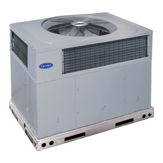
Fig. 1 - - Unit 48ES
(Low NOx Model Available)
. . . . . . . . . . . . . . . . . . . . . . . . . . . . . . . .
. . . . . . . . . . . . . . . . . . . . . . . . .
. . . . . . . . . . . . . .
. . . . . . . . . . . . . . . . . . . . . . . . . . . .
. . . . . . . . . . . . . . . . . . . . . . . . . . . . . . . . . . .
. . . . . . . . . . . . . . . . . . . . . . . . . . . . . . . . .
. . . . . . . . . . . . . . . . . . . . . . . . . . . . . . . . . . .
. . . . . . . . . . . . . . . . . . . . . . . . . . . .
. . . . . . . . . . . . . . . . . . . . . . . . . . . . . . . . . . .
. . . . . . . . . . . . . . . . . . . . .
. . . . . . . . . . . . . . . . . . . . . . . . . . . . . . .
. . . . . . . . . . . . . . . . . . . . . . . . . . . . . .
. . . . . . . . . . . . . . . . . . . . . . . . . . . . . . . . . . . .
. . . . . . . . . . . . . . . . . . . . . . . . . . . . . .
. . . . . . . . . . . . . . . . . . . . . . . . . . . .
A08438
27- -30
27
27
28
28
28
28
28
28
. . . .
28
29
29
29
30
30
30
31
31
Advertisement
Table of Contents

Related Manuals for Carrier SEER 48ES


Summary of Contents for Carrier SEER 48ES
-
Page 1: Table Of Contents
48ES Comfort t 13 SEER Single ---Packaged Air Conditioner and Gas Furnace System with Puron® (R ---410A) Refrigerant Single and Three Phase Sizes 024---060 Installation Instructions NOTE: Read the entire instruction manual before starting the installation. NOTE: Installer: Make sure the Owner’s Manual and Service Instructions are left with the unit after installation. -
Page 2: Introduction
(NFGC) NFPA 54/ANSI Z223.1, and the National Electrical Code (NEC) NFPA 70. In Canada refer to the current editions of the National Standards of Canada CAN/CSA- -B149.1 and .2 Natural Gas and Propane Installation codes, and Canadian Electrical Code CSA C22.1 Recognize safety information. - Page 3 A08552 Fig. 3 - - 48ES024- -036 Unit Dimensions...
- Page 4 A08553 Fig. 4 - - 48ES042- -060 Unit Dimensions...
- Page 5 HVAC unit base Scre w Gask eting (NO TE A) inner flange* *Gask eting outer flange Wood nailer* Flashing field supplied Roof curb* Insulation (field supplied) Roofing material field supplied Ductwork field supplied Cant str ip field supplied Roof *Provided with roof curb Roof Curb for Small Cabinet Note A: When unit mounting scre w is used, retainer bra cke t must also be used.
-
Page 6: Provide Clearances
Step 4 — Provide Clearances The required minimum operating and service clearances are shown in Fig. 3 and 4. Adequate combustion, ventilation and condenser air must be provided. IMPORTANT: Do not restrict outdoor airflow. An air restriction at either the outdoor- -air inlet or the fan discharge may be detrimental to compressor life. - Page 7 UNIT SIZE NOMINAL CAPACITY (ton) SHIPPING WEIGHT** lb. SHIPPING WEIGHT** (kg) COMPRESSORS Quantity REFRIGERANT (R --- 410A) Quantity lb. Quantity (kg) REFRIGERANT METERING DEVICE OUTDOOR COIL Rows...Fins/in. Face Area (sq ft) OUTDOOR FAN Nominal CFM Diameter in. Diameter (mm) Motor Hp (Rpm) INDOOR COIL Rows...Fins/in.
-
Page 8: Connect Condensate Drain
SMALL CABINET Unit * Rigging Weight * For 460 volt units add 14 lb (6.35 kg) to the rigging weight. NOTE: See dimensional drawing for corner weights. Step 6 — Connect Condensate Drain NOTE: When installing condensate drain connection be sure to comply with local codes and restrictions. - Page 9 For natural gas applications, the gas pressure at unit gas connection must not be less than 4.0 in. wc or greater than 13 in. wc while the unit is operating. For propane applications, the gas pressure must not be less than 11.0 in. wc or greater than 13 in. wc at the unit connection.
-
Page 10: Install Duct Connections
NOMINAL INTERNAL IRON PIPE DIAMETER SIZE (IN.) (IN.) .622 .824 1.049 1--- 1/4 1.380 1400 1--- 1/2 1.610 2100 1460 *Capacity of pipe in cu ft of gas per hr for gas pressure of 0.5 psig or less. Pressure drop of 0.5 ---in. wc (based on a 0.60 specific gravity gas). Refer to Table, National Fire Protection Association NFPA 54. -
Page 11: Install Electrical Connections
Adhere to the following criteria when selecting, sizing, and installing the duct system: 1. Units are shipped for horizontal duct installation (by removing duct covers). 2. Select and size ductwork, supply- -air registers, and return- -air grilles according to American Society of Heating, Refrigeration and Air Conditioning Engineers (ASHRAE) recommendations. -
Page 12: Special Procedures For 208- -V Operation
4. Connect field L1 to black wire on connection 11 of the compressor contactor. 5. Connect field wire L3 to yellow wire on connection 13 of the compressor contactor. 6. Connect field wire L2 to blue wire from compressor. Special Procedures for 208- - v Operation WARNING ELECTRICAL SHOCK HAZARD Failure to follow this warning could result in personal... -
Page 13: Start- -Up
Use the Start- -Up Checklist supplied at the end of this book and proceed as follows to inspect and prepare the unit for initial start- -up: 1. Remove access panel. 2. Read and follow instructions on all DANGER, WARNING, CAUTION, and INFORMATION labels attached to, or shipped with unit. -
Page 14: Check Gas Input
3. The induced- -draft motor will start. 4. On a call for heating, the main burner should light within 5 sec. of the sparker being energized. If the burners do not light, there is a 22- -sec. delay before another 5- -sec. try. If the burners still do not light, this sequence is repeated. -
Page 15: Check Burner Flame
4. 112.5 x 1050 = 118,125 Btuh input. If the desired gas input is 115,000 Btuh, only a minor change in the manifold pressure is required. Observe manifold pressure and proceed as follows to adjust gas input: 1. Remove regulator cover screw over plastic adjustment screw on gas valve (See Fig. - Page 16 A08052 Fig. 15 - - 208/230- -1- -60 Wiring Diagram...
- Page 17 A08053 Fig. 16 - - 208/230- -3- -60 Wiring Diagram...
- Page 18 A08010 Fig. 17 - - 460- -3- -60 Wiring Diagram...
-
Page 19: Limit Switches
Limit Switches Normally closed limit switch (LS) completes the control circuit. Should the leaving- -air temperature rise above the maximum allowable temperature, the limit switch opens and the control circuit “breaks.” Any interruption in the control circuit instantly closes the gas valve and stops gas flow to the burners and pilot. The blower motor continues to run until LS resets. -
Page 20: Indoor Airflow And Airflow Adjustments
NOTE: If the problem causing the inaccurate readings is a refrigerant leak, refer to the Check for Refrigerant Leaks section. Indoor Airflow and Airflow Adjustments CAUTION UNIT OPERATION HAZARD Failure to follow this caution may result in unit damage. For cooling operation, the recommended airflow is 350 to 450 cfm for each 12,000 Btuh of rated cooling capacity. - Page 21 Table 7 – Cooling Charging Chart A08490...
- Page 22 FILTER SIZE in. (mm) 20X20X1 0.05 0.07 0.08 0.12 0.13 0.14 0.15 (508X508X25) 20X24X1 — — — — 0.09 0.10 (508X610x25) 24X30X1 — — — 0.04 0.05 0.06 0.07 0.07 0.08 0.09 (610X762x25) 24X36X1 — — — — (610X914X25) Table 9 – Dry Coil Air Delivery* - - Horizontal and Downflow Discharge - - Heating Motor Unit...
- Page 23 Table 9 - - Dry Coil Air Delivery* - - Horizontal and Downflow Discharge - - Heating Motor Unit Rise Range Speed Med---Low 30 --- 60 48ES( ---,N)030040 Medium (17 --- 33 Med---High High Med---Low 25 --- 55 48ES( ---,N)030060 Medium (14 --- 31 Med---High...
- Page 24 Table 9 - - Dry Coil Air Delivery* - - Horizontal and Downflow Discharge - - Heating Motor Unit Rise Range Speed Med---Low 35 --- 65 48ES( ---,N)036090 Medium (19 --- 36 Med---High High Med---Low 25 --- 55 48ES( ---,N)042060 Medium (14 --- 31 Med---High...
- Page 25 Table 9 - - Dry Coil Air Delivery* - - Horizontal and Downflow Discharge - - Heating Motor Unit Rise Range Speed Med---Low 35 --- 65 48ES( ---,N)048090 Medium (19 --- 36 Med---High High Med---Low 30 --- 60 48ES( ---,N)048115 Medium (17 --- 33 Med---High...
- Page 26 Table 9 - - Dry Coil Air Delivery* - - Horizontal and Downflow Discharge - - Heating Motor Unit Rise Range Speed Med---Low 35 --- 65 48ES( ---,N)060090 Medium (19 --- 36 Med---High High Med---Low 30 --- 60 48ES( ---,N)060115 Medium (17 --- 33 Med---High...
-
Page 27: Maintenance
UNIT SIZE 0.030 0.037 0.044 0.053 0.037 0.044 0.053 0.055 MAINTENANCE To ensure continuing high performance and to minimize the possibility of premature equipment failure, periodic maintenance must be performed on this equipment. This inspected at least once each year by a qualified service person. To troubleshoot unit, refer to Table 11, Troubleshooting Chart. -
Page 28: Induced Draft (Combustion Air) Blower
e. Loosen setscrew(s) that secures wheel to motor shaft, remove screws that secure motor mount brackets to housing, and slide motor and motor mount out of housing. 2. Remove and clean blower wheel as follows: a. Ensure proper reassembly by marking wheel orientation. b. -
Page 29: Outdoor Fan
FRONT ACCESS PANEL Fig. 20 - - Unit Access Panel Fig. 21 - - Removal of Motor and Blower Wheel Fig. 22 - - Burner Rack Removed Outdoor Fan UNIT OPERATION HAZARD Failure to follow this caution may result in damage to unit components. -
Page 30: Gas Input
MOTOR MAX DISTANCE BETWEEN FAN HUB AND END OF MOTOR SHAFT SIZE Gas Input The gas input does not require checking unless improper heating performance is suspected. If a problem exists, refer to the Start- -Up section. Evaporator Airflow The heating and/or cooling airflow does not require checking unless improper performance is suspected. -
Page 31: Troubleshooting
pressure. The relief port has an operating range between 550 (26.34 kPa) and 625 psi (29.93 kPa) differential pressure. WARNING EXPLOSION, ENVIRONMENTAL HAZARD Failure to follow this warning could result in personal injury, death or equipment damage. This system uses Puron (R- -410A) refrigerant which has higher operating pressures than R- -22 and other refrigerants. - Page 32 PURONR (R- -410A) QUICK REFERENCE GUIDE S Puron refrigerant operates at 50- -70 percent higher pressures than R- -22. Be sure that servicing equipment and replacement components are designed to operate with Puron S Puron refrigerant cylinders are rose colored. S Recovery cylinder service pressure rating must be 400 psig, DOT 4BA400 or DOT BW400.
- Page 33 SYMPTOM Compressor and condenser fan will not start. Compressor will not start but condenser fan runs Three- -phase scroll compressor makes excessive noise, and there may be a low pressure differential. Compressor cycles (other than normally sat- isfying thermostat) Compressor operates continuously Excessive head pressure Head pressure too low Excessive suction pressure...
- Page 34 SYMPTOM Water in gas line No power to furnace No 24--v power supply to control circuit Burners will not ignite Mis--wired or loose connections Misaligned spark electrodes No gas at main burners Dirty air filter Gas input to furnace too low Unit undersized for application Inadequate heating Restricted airflow...
- Page 35 I. PRELIMINARY INFORMATION MODEL NO.: SERIAL NO.: DATE: TECHNICIAN: II. PRESTART- -UP (Insert check mark in box as each item is completed) ( ) VERIFY THAT ALL PACKING MATERIALS HAVE BEEN REMOVED FROM UNIT ( ) REMOVE ALL SHIPPING HOLD DOWN BOLTS AND BRACKETS PER INSTALLATION INSTRUCTIONS ( ) CHECK ALL ELECTRICAL CONNECTIONS AND TERMINALS FOR TIGHTNESS ( ) CHECK GAS PIPING FOR LEAKS (WHERE APPLICABLE) ( ) CHECK THAT INDOOR (EVAPORATOR) AIR FILTER IS CLEAN AND IN PLACE...
- Page 36 Copyright 2008 Carrier Corp. S 7310 W. Morris St. S Indianapolis, IN 46231 Manufacturer reserves the right to change, at any time, specifications and designs without notice and without obligations. Printed in U.S.A. Edition Date: 11/08 Catalog No: 48ES---03SI Replaces: 48ES--- 2SI...