Carrier Performance 50VL-A Installation Instructions Manual
14 seer single-packaged air conditioner system with puron (r-410a) refrigerant single and three phase 2-5 nominal tons (sizes 24-60)
Hide thumbs
Also See for Performance 50VL-A:
- Installation instructions manual (50 pages) ,
- Owner's information manual (6 pages) ,
- Installation instructions manual (22 pages)
Table of Contents
Advertisement
50VL---A
Performancet 14 SEER Single ---Packaged Air Conditioner
System with Puron® (R ---410A) Refrigerant
Single and Three Phase
2---5 Nominal Tons (Sizes 24---60)
NOTE:
Read the entire instruction manual before starting the
installation.
NOTE:
Installer: Make sure the Owner's Manual and Service
Instructions are left with the unit after installation.
TABLE OF CONTENTS
SAFETY CONSIDERATIONS
. . . . . . . . . . . . . . . . . . . . . . . . . . . . . . . . . . .
. . . . . . . . . . . . . . . . . . . . . . . . . . . . . . . . . .
. . . . . . . . . . . . . . . . . . . . . . . . . . . . . . . . . . . .
. . . . . . . . . . . . . . . . . . . . . . . . . . . . . . . . .
. . . . . . . . . . . . . . . . . . . . . . . . . . . . . . .
. . . . . . . . . . . . . . . . . . . . . . . . . . . . . . . . . . . . . .
. . . . . . . . . . . . . . . . . . . . . . . . . . . . . . . . . . . . .
. . . . . . . . . . . . . . . . . . . . . . . . . . . . . . . . .
. . . . . . . . . . . . . . . . . . . . . . . . . . . .
. . . . . . . . . . . . . . . . . . . . . . . . . . . . . . . . .
. . . . . . . . . . . . . . . . . . . . . . . . . . . . . . . . . . . . . .
. . . . . . . . . . . . . . . . . . . . . . . . . . . .
. . . . . . . . . . . . . . . . . . . . . . . . . . . . .
. . . . . . . . . . . . . . . . . . . . . . . . . . . . .
. . . . . . . . . . . . . . . . . . . . . . . . . . .
. . . . . . . . . . . . . . . . . . . . . . . . . . . . . . . . . . .
. . . . . . . . . . . . . . . . . . . . . . . . . . . . . . . . . . . . .
. . . . . . . . . . . . . . . . . . . . . . . . . . . . . .
. . . . . . . . . . . . . . . . . . . . . . . . . . . . . . . .
. . . . . . . . . . . . . . . . . . . . . . . . . . . . . . . . . . . . . .
. . . . . . . . . . . . . . . . . . . . . . . . . . . . . . . . . . .
. . . . . . . . . . . . . . . . . . . . . . . . . . . . . . .
. . . . . . . . . . . . . . . . . . . . . . . . . . . . . .
. . . . . . . . . . . . . . . . . . . . . . . . . . . . . . . . . . . .
. . . . . . . . . . . . . . . . . . . . . . . . . . . . . .
. . . . . . . . . . . . . . . . . . . . . . . . . . . .
Installation Instructions
. . . . . . . . . . . . . . . . . . . . . . .
. . . . . . . . . . . . . . . . .
. . . . . . . . . . . . . . . . . . . . . . . . . . .
. . . .
. . . . . . . . . . . . . . . . . . . . . . . . .
. . . . . . . . . . . . . . . . . . . . . . . . .
. . . . . . . . . . . . . . .
. . . . . . . . . . . . . . . . . . . . . . .
. . . . . . . . . . . . . . . . . . . . . . . . .
. . . . . . . . . . . . . . . .
. . . . . . . . . . .
. . . . . . . . . . . . .
. . . . . . . . . . . . . . . . . . . . . . . .
. . . . . . . . . . . . . . . . . . . . .
. . . . . . . . . . . . . . . . . . . . . . . . .
. . .
. . . . . . . . . . . . . . . . . . . . .
PAGE
1- -2
2
2- -10
2
2
2
2
2
2
7
7
7
7
7
8
SAFETY CONSIDERATIONS
8
8
Improper installation adjustment, alteration, service, maintenance,
9
or use can cause explosion, fire, electrical shock, or other
9
conditions which may cause death, personal injury, or property
10
damage. Consult a qualified installer, service agency, or your
10
distributor or branch for information or assistance. The qualified
10
installer or agency must use factory- -authorized kits or accessories
10
when modifying this product Refer to the individual instructions
12
packaged with the kits or accessories when installing.
12- -14
Follow all safety codes. Wear safety glasses, protective clothing,
12
and work gloves. Use quenching cloth for brazing operations.
12
Have a fire extinguisher available. Read these instructions
12
thoroughly and follow all warnings or cautions included in
12
literature and attached to the unit. Consult local building codes, the
13
current editions of the National Electrical Code (NEC) NFPA 70.
14
In Canada refer to the current editions of the Canadian electrical
14
Code CSA C22.1.
24- -26
Recognize safety information. This is the safety- -alert symbol
24
When you see this symbol on the unit and in instructions or
24
manuals, be alert to the potential for personal injury. Understand
25
these signal words; DANGER, WARNING, and CAUTION. These
25
words are used with the safety- -alert symbol. DANGER identifies
25
the most serious hazards which will result in severe personal injury
26
or death. WARNING signifies hazards which could result in
26
personal injury or death. CAUTION is used to identify unsafe
26
practices which may result in minor personal injury or product and
27
property damage. NOTE is used to highlight suggestions which
27
will result in enhanced installation, reliability, or operation.
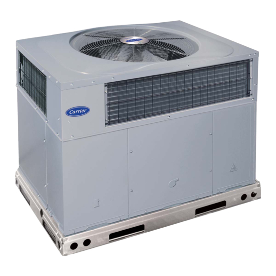
1
Fig. 1 - - Unit 50VL- -A
A09033
.
Advertisement
Table of Contents

Related Manuals for Carrier Performance 50VL-A


Summary of Contents for Carrier Performance 50VL-A
-
Page 1: Table Of Contents
50VL---A Performancet 14 SEER Single ---Packaged Air Conditioner System with Puron® (R ---410A) Refrigerant Single and Three Phase 2---5 Nominal Tons (Sizes 24---60) Installation Instructions NOTE: Read the entire instruction manual before starting the installation. NOTE: Installer: Make sure the Owner’s Manual and Service Instructions are left with the unit after installation. -
Page 2: Introduction
INTRODUCTION The 50VL- -A packaged air conditioner is fully self- -contained and designed for outdoor installation (See Fig.1 ). See Fig. 2 and 3 for unit dimensions. All unit sizes have discharge openings for both horizontal and downflow configurations, and are factory shipped with all downflow duct openings covered. - Page 3 A09462 Fig. 2 - - 50VL- -A24- -36 Unit Dimensions...
- Page 4 A09463 Fig. 3 - - 50VL- -A42- -60 Unit Dimensions...
- Page 5 HVAC unit HVAC unit basepan base rails Anchor screw Flashing field supplied Roofing material field supplied Cant strip field supplied *Provided with roofcurb ROOF CURB DETAIL LARGE CURB UNIT CATALOG (small/common SIZE NUMBER (mm) CPRFCURB010A00 Small (279) Large CPRFCURB011A00 (356) CPRFCURB012A00 (279) Large...
- Page 6 CAUTION - NOTICE TO RIGGERS PRUDENCE - AVIS AUX MANIPULATEUR ACCESS PANELS MUST BE IN PLACE WHEN RIGGING. PANNEAUX D'ACCES DOIT ÊTRE EN PLACE POUR MANIPULATION. Use top skid as spreader bar. / Utiliser la palette du haut comme barre de répartition SEE DETAIL A VOIR DÉTAIL A SMALL CABINET...
-
Page 7: Provide Clearances
Step 3 — Provide Clearances The required minimum service clearances are shown in Fig. 2 and 3. Adequate ventilation and outdoor air must be provided. The outdoor fan draws air through the outdoor coil and discharges it through the top fan grille. Be sure that the fan discharge does not recirculate to the outdoor coil. -
Page 8: Connect Condensate Drain
Step 6 — Connect Condensate Drain NOTE: When installing condensate drain connection be sure to comply with local codes and restrictions. Model 50VL- -A disposes of condensate water through a 3/4 in. NPT fitting which exits through the base on the evaporator coil access side. -
Page 9: Install Electrical Connections
Horizontal Duct Covers Basepan Downflow (Vertical) Supply Knockout Fig. 9 - - Supply and Return Duct Opening Step 8 — Install Electrical Connections WARNING ELECTRICAL SHOCK HAZARD Failure to follow this warning could result in personal injury or death. The unit cabinet must have an uninterrupted, unbroken electrical ground to minimize the possibility of personal injury if an electrical fault should occur. -
Page 10: Special Procedures For 208V Operation
HIGH VOLTAGE POWER LEADS (SEE UNIT WIRING LABEL) 3-PHASE SHOWN 1-PHASE USES TWO POWER EQUIP GR LEADS FIELD-SUPPLIED FUSED DISCONNECT CONTROL BOX WHT(W1) VIO (W2) YEL(Y) GRN(G) LOW-VOLTAGE RED(R) POWER LEADS (SEE UNIT BRN(C) WIRING LABEL) BLU (DH) GRA (Y2) SPLICE BOX Fig. - Page 11 UNIT SIZE NOMINAL CAPACITY (ton) SHIPPING WEIGHT* lb. SHIPPING WEIGHT* (kg) COMPRESSORS Quantity REFRIGERANT (R --- 410A) Quantity lb Quantity (kg) REFRIGERANT METERING DEVICE OUTDOOR COIL Rows...Fins/in. 1...21 Face Area (sq ft) 11.9 OUTDOOR FAN Nominal Cfm 2500 Diameter in. Diameter (mm) 609.6 Motor Hp (Rpm)
-
Page 12: Pre- -Start- -Up
PRE- -START- - UP WARNING ENVIRONMENTAL, FIRE, ELECTRICAL SHOCK HAZARD Failure to follow this warning could result in personal injury or death and/or property damage. 1. Follow recognized safety practices and wear protective goggles when checking or servicing refrigerant system. 2. -
Page 13: Indoor Airflow And Airflow Adjustments
Proceed as follows: 1. Remove caps from low- - and high- -pressure service fittings. 2. Using hoses with valve core depressors, attach low- - and high- -pressure gauge hoses to low- - and high- -pressure service fittings, respectively. 3. Start unit and let run until system pressures stabilize. 4. -
Page 14: Continuous Fan Operation
HIGH R13 C8 AB A15 D5 D3 R3 R5 R6 R W2 Y W3 W3 W2 W2 C SSTZ-8 Fig. 11 - - Interface Fan Board (IFB) SINGLE SPEED COOLING WITH HIGHER ELECTRIC HEAT SPEED This unit can also be configured to operate with single speed cooling and a higher speed for an accessory electric heater. - Page 17 A11004 Fig. 12 - - Connection Wiring Diagram 208/230- -1- -60...
- Page 18 A11003 Fig. 12 Cont. - - Ladder Wiring Diagram 208/230- -1- -60...
- Page 19 A11010 Fig. 13 - - Connection Wiring Diagram 208/230- -3- -60...
- Page 20 A11009 Fig. 13 Cont. - - Ladder Wiring Diagram 208/230- -3- -60...
- Page 21 DANGER: ELECTRICAL SHOCK HAZARD DISCONNECT POWER BEFORE SERVICING IF USED FIELD SUPPLY POWER UNIT ONLY MAXIMUM WIRE SIZE 2 AWG. EQUIP_GND ECON PLUG ECON TRAN TSTAT SEE NOTE UNIT COMPONENT ARRANGEMENT OUTDOOR FAN SECTION COMPRESSOR INDOOR FAN CONTROL BOX AREA SECTION SECTION SINGLE PT.
- Page 22 DANGER: ELECTRICAL SHOCK HAZARD DISCONNECT POWER BEFORE SERVICING IF USED SEE NOTE 24VAC FUSE P1-1 "R" P1-2 "C" P1-3 "Y1/Y" P1-4 "G" P1-5 "Y2/DH" P1-6 "W2" P1-7 "W3" P2-1 P2-2 P2-3 P2-4 ACCESSORY ELECTRIC HEAT P4-1 P4-2 P4-3 P4-4 P4-5 SEE NOTE DEHUM SEE NOTE...
- Page 23 A09089 Fig. 15 - - Cooling Charging Chart...
-
Page 24: Maintenance
MAINTENANCE To ensure continuing high performance, and to minimize the possibility of premature equipment failure, periodic maintenance must be performed on this equipment. This cooling unit should be inspected at least once each year by a qualified service person. To troubleshoot unit, refer to Table 8, Troubleshooting Chart. -
Page 25: Outdoor Coil, Indoor Coil, And Condensate Drain Pan
MAX DISTANCE BETWEEN TOP OF FAN GRILLE AND BOTTOM OF FAN BLADE SIZE Compressor Access Panel Fig. 17 - - Unit Access Panels Outdoor Coil, Indoor Coil, and Condensate Drain Pan Inspect the condenser coil, evaporator coil, and condensate drain pan at least once each year. -
Page 26: Refrigerant Circuit
These pressure switches are specifically designed to operate with Puron (R- -410A) systems. R- -22 pressure switches must not be used as replacements for the Puron (R- -410A) air conditioner. Loss of Charge/Low- - Pressure Switch (Air Conditioner Only) -
Page 27: Troubleshooting
readily. POE oils can absorb 15 times as much water as other oils designed for HCFC and CFC refrigerants. Take all necessary precautions to avoid exposure of the oil to the atmosphere. Servicing Systems on Roofs with Synthetic Materials POE (polyolester) compressor lubricants are known to cause long term damage to some synthetic roofing materials. - Page 28 SYMPTOM Compressor and outdoor fan will not start Compressor will not start but condenser fan runs Three- -phase scroll compressor (size 30- - 60 unit) has a low pressure differential Compressor cycles (other than normally satisfying) cooling/heating calls Compressor operates continuously Excessive head pressure Head pressure too low Excessive suction pressure...
- Page 29 AIR CONDITIONER WITH PURON (R- -410A) QUICK REFERENCE GUIDE Puron refrigerant operates at 50- -70 percent higher pressures than R- -22. Be sure that servicing equipment and replacement components are designed to operate with Puron. Puron refrigerant cylinders are rose colored.
- Page 30 * Measured at suction inlet to compressor { Measured at liquid line leaving condenser. Copyright 2011 Carrier Corp. S 7310 W. Morris St. S Indianapolis, IN 46231 Manufacturer reserves the right to change, at any time, specifications and designs without notice and without obligations.