Table of Contents
Advertisement
42 Series
Fan Coil Units
Application Data
Control Selection Guide
for Fan Coil Air Conditioners
Manufacturer reserves the right to discontinue, or change at any time, specifications or designs without notice and without incurring obligations.
Book 3
PC 201
Catalog No. 514-203
Printed in U.S.A.
Form 42-3XC
Pg 1
6-90
Replaces: 42-2XC
Tab
7a
Advertisement
Table of Contents

Related Manuals for Carrier 42 SERIES


Summary of Contents for Carrier 42 SERIES
-
Page 1: Application Data
42 Series Fan Coil Units Application Data Control Selection Guide for Fan Coil Air Conditioners Manufacturer reserves the right to discontinue, or change at any time, specifications or designs without notice and without incurring obligations. Book 3 PC 201 Catalog No. 514-203 Printed in U.S.A. -
Page 2: Table Of Contents
CONTROL SELECTION GUIDE ....3 STANDARD WIRING PACKAGES ... . 4-8 Manual Fan Control ......4 Thermostatic Fan Control, 2-Pipe Systems . -
Page 3: Control Selection Guide
Use this guide to make sure that all necessary components are provided for and that the components are compatible with the required control system. NOTE: When thermostatic fan control is selected or when unit outside air dampers are used, unit-mounted thermostats are not recommended as their use will result in poor room temperature sensing. -
Page 4: Standard Wiring Packages
STANDARD WIRING PACKAGES IMPORTANT: Wiring diagrams shown depict typical control functions. Refer to unit wiring label for spe- cific functions. Manual Fan Control — On all Vertical Cabinet units, the standard fan-speed switch is furnished unit-mounted and wired. On all Vertical Furred-In units and all Horizontal units, the switch is shipped separately on a decorative wall plate for field mounting and wiring. -
Page 5: Thermostatic Fan Control, 2-Pipe System With Safety Cycle
Thermostatic Fan Control, 2-Pipe System with Safety Cycle — This control is used for high humidity situations in which condensate problems can occur if fan is turned off while chilled water is still running through the coil. The wiring provides fan cycling from HIGH to LOW on the cooling cycle and from LOW to OFF on the heating cycle. -
Page 6: Thermostatic 2-Pipe Auxiliary Electric Heat With Valve Control
STANDARD WIRING PACKAGES (cont) Thermostatic 2-Pipe Auxiliary Electric Heat with Valve Control — This system, also called Twi- light or Intermediate Season electric heat, goes a long way towards solving the spring and fall control problems of 2-pipe systems. You can run chilled water late into the fall, turn it on early in the spring and still have heat available to all units when- ever required. -
Page 7: Thermostatic 2-Pipe Total Electric Heat With Valve Control
Thermostatic 2-Pipe Total Electric Heat with- Valve Control — With this system, the complete heat- ing requirement for the space is provided by the electric heater; the water system is never changed over for heating. It is there- fore possible, just as with 4-pipe systems, to have heating or cooling at any time of the year. -
Page 8: Thermostatic Valve Control, 4-Pipe
STANDARD WIRING PACKAGES (cont) Thermostatic Valve Control, 4-Pipe — system provides the ultimate in economy and room tem- perature control. Both hot water and chilled water are avail- able at any time. Normally an automatic changeover thermostat is used, but a manual changeover thermostat is also suitable. -
Page 9: Electric Heat
ELECTRIC HEAT Application — Electric heaters are available for in-stallation on Carrier fan coil units in the following applications. TOTAL ELECTRIC HEAT — This system provides com- plete heating during the heating season; no boiler is re- quired. Heating and cooling are now available on an indi- vidual basis throughout the year with a 2-pipe system. -
Page 10: Remote-Mounted Controls
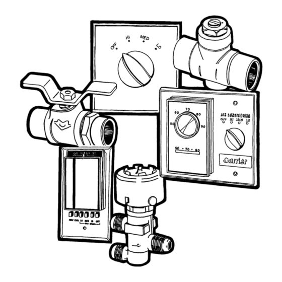
REMOTE-MOUNTED CONTROLS Standard 3-Speed Switch — has 4 positions: OFF, HIGH, MEDIUM, and LOW. Switch has auxiliary contact that is energized when switch is in HIGH, MEDIUM or LOW position. Some of the options common with the 3-speed switch are: 1. -
Page 11: Alternate Wall Thermostats
ALTERNATE WALL THERMOSTATS Wall Thermostat (Honeywell Model T4039) with Manual 3-Speed Fan Switch and ON-OFF Switch Temperature range is approximately 55 to 95 F in 10° F increments from 75 F midpoint. Scale is marked warmer- cooler. Thermostat mounts in 4-in. square junction box or 2-ganged outlet boxes. -
Page 12: Unit Mounted Controls
UNIT-MOUNTED CONTROLS Standard 3-Speed Switch — Switch has OFF, HIGH, MED and LOW positions. Switch is also equipped with aux- iliary connection energized when switch is in HIGH, MED or LOW position. Combination Thermostat/3-Speed Switch ages 24-L, M, N, P and Q*) — Thermostat and standard switch are unit mounted in a common electrical junction box. -
Page 13: Two-Pipe Thermostat
Two-Pipe Thermostat, Model TF103 — pole, double-throw (SPDT) thermostat has snap-action con- tacts. The standard temperature range is 60 - 90 F. Four-Pipe Thermostat, Model TH104 — thermostat, heating and cooling are sequenced (automatic changeover) with 6 degree separation between HEATING ON and COOLING ON. -
Page 14: Basic Definitions
BASIC DEFINITIONS Unit Hand — When facing the supply air outlet from the front of the unit (air blow- ing in your face), your right hand will be the right hand side of the unit and your left hand the left hand side of the unit. Same End Connection (2 Pipe or 4 Pipe) —... -
Page 15: Field Piping Connections
Hydronic Coil Arrangement FIELD PIPING CONNECTIONS* *Location of field piping connections will vary depending on number of coil rows on factory- supplied coil or arrangement of factory-supplied valves. VERTICAL FLOOR UNITS — 42VB, VE, VF Pipe into cabinet end compartment (opening in bottom and back). -
Page 16: Valve Packages
VALVE PACKAGES General — Table 1 lists acceptable pneumatic valves for installation on 42 series fan coil units. There are limitations on physical size of pneumatic valves, quantity and type of matching components, required control interface. See Fig. 1 for symbols and placement of valves. - Page 17 Component Sizing — ⁄ nominal (for Manual Air Vent — Standard component - Brazed into high point of hydronic cooling and/or heating coil circuit. Automatic Air Vent — Brazed into high point of coil circuit. Coil Connections (Positions A & B) — When isolation valve only is added to supply or return line, the isolation valve will be factory brazed to the coil stub-out.
-
Page 18: Two-Way Motorized Control Valve
VALVE PACKAGES (cont) Two-Way Motorized Control Valve The 2-way motorized valve motor drives valve open and a spring returns valve to normally closed position (no water flow with unit OFF). Supply connection at coil will be swage fit for field braze (standard) or union (option). -
Page 19: Three-Way Motorized Control Valve
Three-Way Motorized Control Valve On the 3-way motorized valve flow is normally closed to coil and open to system return. Motor closes bypass flow to system return while opening flow through coil. Water bypasses coil and flows directly to system return when unit is OFF. -
Page 20: Valve Package Arrangements
VALVE PACKAGE ARRANGEMENTS... - Page 21 LEGEND — Ball Valve — Ball Valve with Memory Stop — Gate Shut Off Valve — Balancing Valve — Circuit Setter — Motorized 2-Way Valve — Motorized 3-Way Valve * When aquastat is used for automatic changeover, bypass is re- quired as indicated by dashed line.
- Page 22 VALVE PACKAGE ARRANGEMENTS (cont) LEGEND ITEM DESCRIPTION Pneumatic Control Valve, 2-Way Code 18(typical) -2* ( ⁄ - or Code 18(typical) -3* ( ⁄ -in. ODF tubing conn) Pneumatic Control Valve, 3-Way Code 18(typical) -14* ( ⁄ - or Code 18(typical) -5* ( ⁄...
- Page 23 Table 1 — Acceptable Field-Furnished Pneumatic Valves MANUFACTURER VALVE NUMBER VP517A VP522A&B VP526A HONEYWELL VP527A VP513A VP513B VP531A V4332 V4334 V4440 JOHNSON SERVICE V4440 V3766 V3966 VK9312 VK9332 BARBER- COLEMAN VK9212 VK9222 VP656-0011, 10, 09 VP658-0004, 5 VP658-0050, 51 POWERS VP658-0004, 5 VP656-0002, 4 VP656-0012...
-
Page 24: Piping Components
PIPING COMPONENTS SYMBOL/SKETCH MANUAL AIR VENT: Threaded brass needle valve with screwdriver slot for adjustment. Application - Body brazed into high point of heating and cooling coils for bleeding air from coil. Standard item on all hydronic coils (not used on steam or DX coils). - Page 25 SYMBOL/SKETCH PRESSURE TEST PORT: Brass body ⁄ service access fitting with removable depressor type core. Application - Installed on both sides of the coil to allow for pressure sensing. Attach pressure gages to facilitate close tolerance water balancing. GAGE COCK: Brass shut-off valve with ⁄...
- Page 26 PIPING COMPONENTS (cont) SYMBOL/SKETCH STRAINER: Y-type body with 50 mesh stainless steel screen. Application - Used for removal of small particles from system water during normal system operation. Should not be used in lieu of main system strainers. Strainer screen may have to be removed during initial high pressure system flushing during start-up.
- Page 27 SYMBOL/SKETCH 2-WAY MOTORIZED VALVE: Electric 2-position flow control valve (open/closed). Normally-closed body with manual override lever. Installed in supply line to unit. Application - All standard control and valve packages are based upon normally-closed valves (valve electrically powered open and closed by spring return when electric power removed).
-
Page 28: Cv Factor Vs Water Pressure Drop
C V FACTOR vs WATER PRESSURE DROP C V FACTOR: The flow rate in gallons per minute (gpm) through a piping component when the pressure drop ( P) in pounds per square inch (psi) across the component is 1.0 (psi). Pressure drop (ft-H O) = 2.31 x psi (pressure drop) GRAPH EXAMPLE:... -
Page 30: Copper Water Tube And Joint Material Pressure Ratings
COPPER WATER TUBE AND JOINT MATERIAL PRESSURE RATINGS 50-50 Lead-Tin at 200 F 50-50 Lead-Tin at 150 F 50-50 Lead-Tin at 100 F 1. Not recommended for high system water pressures. 2. Standard factory joint material. THE ABOVE CHART IS FOR REFERENCE ONLY: Check all system component pressure ratings (coils, valves, pumps, etc.) and any applicable local or national piping codes prior to specifying system pressure rating. -
Page 31: Correction Factors For Glycol
CORRECTION FACTORS FOR GLYCOL (Equivalent water flow method for all 42 Series Models) This method allows you to calculate cooling and heating performance without adjusting capacities for glycol concentration. After completing the standard selection procedure including water flow rates, use the correction multiplier shown below to determine new (equivalent) flow rates required for the specified glycol concentration. -
Page 32: Standard Accessories And Options
Outdoor Air Connection (6 in.), with filter and with or without damper Damper, Linkage and Motor wired to auxiliary contact of 3-speed switch DECORATIVE COLORS (See Carrier Fan Coil Paint Selector Guide) DISCHARGE GRILLES Stamped Front Discharge Double Deflection, installed Double Deflection, shipped •...