Table of Contents
Advertisement
SAFETY CONSIDERATIONS . . . . . . . . . . . . . . . . . . . 1
BEFORE INSTALLATION . . . . . . . . . . . . . . . . . . . . . 1-3
Rigging . . . . . . . . . . . . . . . . . . . . . . . . . . . . . . . . . . . . . . 1
Placing Unit . . . . . . . . . . . . . . . . . . . . . . . . . . . . . . . . . 3
Mounting Unit . . . . . . . . . . . . . . . . . . . . . . . . . . . . . . . 3
Compressor Mounting . . . . . . . . . . . . . . . . . . . . . . . . 3
INSTALLATION . . . . . . . . . . . . . . . . . . . . . . . . . . . . . 3-12
Refrigerant Piping Connections . . . . . . . . . . . . . . . 3
Liquid Line Solenoid Drop Control . . . . . . . . . . . . 3
Filter Drier and Moisture Indicator . . . . . . . . . . . . 3
Receiver . . . . . . . . . . . . . . . . . . . . . . . . . . . . . . . . . . . . . 4
Piping Procedure . . . . . . . . . . . . . . . . . . . . . . . . . . . . 4
Power Supply . . . . . . . . . . . . . . . . . . . . . . . . . . . . . . . . 6
Power Wiring . . . . . . . . . . . . . . . . . . . . . . . . . . . . . . . . 6
START-UP . . . . . . . . . . . . . . . . . . . . . . . . . . . . . . . . 13-17
Initial Check . . . . . . . . . . . . . . . . . . . . . . . . . . . . . . . . 13
Leak Test and Dehydration . . . . . . . . . . . . . . . . . . 13
Preliminary Charge . . . . . . . . . . . . . . . . . . . . . . . . . . 13
Start Unit . . . . . . . . . . . . . . . . . . . . . . . . . . . . . . . . . . . 13
Charge System . . . . . . . . . . . . . . . . . . . . . . . . . . . . . 13
Operation . . . . . . . . . . . . . . . . . . . . . . . . . . . . . . . . . . . 13
Control Module (CM) . . . . . . . . . . . . . . . . . . . . . . . . 13
Bypass Relay (BPR) . . . . . . . . . . . . . . . . . . . . . . . . . 17
Time-Delay Relay (TDR) . . . . . . . . . . . . . . . . . . . . . 17
Sequence of Operation . . . . . . . . . . . . . . . . . . . . . . 17
Complete Unit Stoppage . . . . . . . . . . . . . . . . . . . . . 17
SERVICE . . . . . . . . . . . . . . . . . . . . . . . . . . . . . . . . . . 17-20
Access for Servicing . . . . . . . . . . . . . . . . . . . . . . . . 17
Fan Adjustment . . . . . . . . . . . . . . . . . . . . . . . . . . . . . 19
Oil Charge . . . . . . . . . . . . . . . . . . . . . . . . . . . . . . . . . . 19
Liquid Shutoff/Charging Valve . . . . . . . . . . . . . . . 19
Capacity Control . . . . . . . . . . . . . . . . . . . . . . . . . . . . 19
Oil Pressure Safety Switch (OPS) . . . . . . . . . . . . 20
Compressor Protection . . . . . . . . . . . . . . . . . . . . . . 20
High-Pressure Switch . . . . . . . . . . . . . . . . . . . . . . . 20
Low-Pressure Switch . . . . . . . . . . . . . . . . . . . . . . . . 20
Winter Start Control . . . . . . . . . . . . . . . . . . . . . . . . . 20
Head Pressure Control . . . . . . . . . . . . . . . . . . . . . . 20
TROUBLESHOOTING . . . . . . . . . . . . . . . . . . . . . . . . 21
START-UP CHECKLIST . . . . . . . . . . . . . . . . . . . . . CL-1
Manufacturer reserves the right to discontinue, or change at any time, specifications or designs without notice and without incurring obligations.
Book 1
PC 111
Tab
3a
Installation, Start-Up and
Service Instructions
Page
Catalog No. 533-820
Printed in U.S.A.
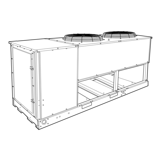
Air-Cooled Condensing Units
CONTENTS
SAFETY CONSIDERATIONS
Installing, starting up, and servicing air-conditioning equip-
ment can be hazardous due to system pressures, electrical
components, and equipment location (roofs, elevated struc-
tures, etc.).
Only trained, qualified installers and service mechanics
should install, start up, and service this equipment (Fig. 1).
Untrained personnel can perform basic maintenance func-
tions such as cleaning coils. All other operations should be
performed by trained service personnel.
When working on the equipment, observe precautions in
the literature and on tags, stickers, and labels attached to the
equipment.
• Follow all safety codes.
• Wear safety glasses and work gloves.
• Keep, quenching cloth and fire extinguisher nearby when
brazing.
• Use care in handling, rigging, and setting bulky
equipment.
• See Table 1A or 1B for physical data.
BEFORE INSTALLATION
Rigging -
Preferred method is with spreader bars from
above the unit. Use 2-in. (50 mm) OD pipe or hooks in lift-
ing holes. Rig with 4 cables and spreader bars. All panels
must be in place when rigging. See rigging label on unit for
details concerning shipping weights, distance between lift-
ing holes, center of gravity, and spreader bar dimensions.
See Fig. 2.
If overhead rigging is not possible, place unit on skid or
pad for rolling or dragging. When rolling, use minimum of
3 rollers. When dragging, pull the pad. Do not apply force
to the unit. When in final position, raise from above to lift
unit off pad.
All panels must be in place when rigging.
Form 38A-5SI
38AKS028-044
50/60 Hz
ELECTRIC SHOCK HAZARD
Open all remote disconnects before
servicing this equipment.
Pg 1
7-94
Replaces: 38AK-3SI
Advertisement
Table of Contents

Related Manuals for Carrier 38AKS028-044


Summary of Contents for Carrier 38AKS028-044
-
Page 1: Table Of Contents
3 rollers. When dragging, pull the pad. Do not apply force to the unit. When in final position, raise from above to lift unit off pad. All panels must be in place when rigging. Printed in U.S.A. Form 38A-5SI Pg 1 38AKS028-044 50/60 Hz 7-94 Replaces: 38AK-3SI... - Page 2 Total Airflow, Cfm Speed, Rpm 60/50 Hz CONDENSER COIL, Type Rows...Fins/in. Total Face Area, sq ft *See Service, Oil Charge, for Carrier-approved oil. NOTE: Circuit breaker is in main power circuit. UNIT 38AKS COMPRESSOR No..Type No. Cyls (ea)...Speed, R/s (60/50 Hz)
-
Page 3: Placing Unit
See Table 2A or 2B. It is important to con- sider liquid lift and compressor oil return. Refer to Part 3 of Carrier System Design Manual for line sizing information, and Fig. 4 for recommended piping details. Liquid Line Solenoid Drop Control —... -
Page 4: Receiver
1. Suction line is connected to coil on same side as the entering air. 2. Lower section is first on and last off. 3. For more complete piping information, refer to Carrier System Design Manual, Part 3. Fig. 4 — Suction Line Piping to Unit with 2 Section Coil Split TXV —... - Page 5 Table 2A — Refrigerant Piping Sizes — 60 Hz UNIT 16-25 (4.9-7.6) 26-50 (7.9-15.2) 38AKS ⁄ ⁄ ⁄ ⁄ ⁄ ⁄ ⁄ ⁄ ⁄ L — Liquid Line S — Suction Line *IMPORTANT — Requires a double suction riser, if evaporator is below condensing unit. See table below. NOTE: Liquid and suction line sizes are OD (in.) Equivalent sizes in mm are listed below.
-
Page 6: Power Supply
Table 3. IMPORTANT: Operating unit on improper supply volt- age, or with excessive phase imbalance, constitutes abuse and may affect Carrier warranty. See Unbalanced 3-Phase Supply Voltage, page 7. Power Wiring — All power wiring must comply with applicable local and national codes. - Page 7 FIELD CONNECTIONS 1. Main Power — Bring wires from the fused disconnect switch through hole in bottom rail of unit to control box (Fig. 6 and 7) and connect terminals 13 line side of terminal block TB1 (see Fig. 8 and 9A or 9B).
- Page 8 LEGEND NEC — National Electrical Code VAV — Variable Air Volume NOTES: 1. There must be minimum (2440 mm) 8 ft. clear air space above unit. 2. The approximate operating weight of the unit is: 50 AND 60 HZ UNIT (Lb) (Kg) 38AKS028...
- Page 9 LEGEND NEC — National Electrical Code NOTES: 1. There must be minimum (2440 mm) 8 ft. clear air space above unit. 2. The approximate operating weight of the unit is: 50 HZ AND 60 HZ UNIT (Lb) (Kg) 38AKS044 2437 1106 38AKS044C 2745...
-
Page 13: Start-Up
See Compressor Mounting section on page 2 and Fig. 3 for loosening compressor bolts. Leak Test and Dehydration — refrigerant system by the pressure method described in the Carrier Training Booklet; GTAC II, Module 4 - System Dehydration. Preliminary Charge — Refer to Carrier Training Book- let;... -
Page 17: Bypass Relay (Bpr)
T1 and T6 of the control module. This jumper must be removed after servicing is com- plete. Failure to remove this jumper is considered abu- sive treatment and will void the Carrier warranty. Bypass Relay (BPR) — All units are equipped with a BPR located in the control section of the control box. - Page 18 TRAN1 TRAN2 COMPRESSOR END AND RIGHT-SIDE VIEW COMPRESSOR END, CONTROL PANEL REMOVED LIQUID LINE SERVICE VALVE COMPRESSOR END, RIGHT-SIDE ACCESS DOOR OIL PRESSURE SAFETY SWITCH COMPRESSOR END, LEFT-SIDE ACCESS DOOR (JUNCTION BOX COVER REMOVED) Fig. 13 — 38AKS Unit with Access Panels Removed...
-
Page 19: Fan Adjustment
Witco Chemical Corp....Suniso 3 GS IMPORTANT: Do not use drained oil or use oil that has been exposed to atmosphere. Refer to Carrier Train- ing Booklet, GTAC II, Module 5, for procedures to add oil. -
Page 20: Oil Pressure Safety Switch (Ops)
Oil Pressure Safety Switch (OPS) — the control circuit stops the compressor and unit, if proper oil pressure differential is not established at start-up or main- tained during operation. If OPS stops the unit, determine the cause and correct before restarting unit. Failure to do so will constitute abuse. -
Page 21: Troubleshooting
SYMPTOM AND PROBABLE CAUSE COMPRESSOR DOES NOT RUN 1. Control circuit breaker tripped 2. Power line open 3. Oil pressure switch tripped 4. Safety device tripped 5. Contactor stuck open 6. Loose terminal connection 7. Improperly wired controls 8. Seized compressor 9. - Page 22 For a free Service Training Material Catalog (STM), call 1-800-962-9212. Ordering instructions are included. Copyright 1994 Carrier Corporation Manufacturer reserves the right to discontinue, or change at any time, specifications or designs without notice and without incurring obligations. Book 1 PC 111 Catalog No.
-
Page 23: Start-Up Checklist
A. Preliminary Information OUTDOOR: MODEL NO. INDOOR: AIR HANDLER MANUFACTURER MODEL NO. ADDITIONAL ACCESSORIES B. Pre-Start-Up OUTDOOR UNIT IS THERE ANY SHIPPING DAMAGE? IF SO, WHERE: WILL THIS DAMAGE PREVENT UNIT START-UP? CHECK POWER SUPPLY. DOES IT AGREE WITH UNIT? HAS THE GROUND WIRE BEEN CONNECTED? HAS THE CIRCUIT PROTECTION BEEN SIZED AND INSTALLED PROPERLY? ARE THE POWER WIRES TO THE UNIT SIZED AND INSTALLED PROPERLY? - Page 24 CHECK THE COMPRESSOR OIL LEVEL SIGHT GLASSES; ARE THE SIGHT GLASSES SHOWING OIL LEVEL AT ⁄ ⁄ FULL? NOTES: Copyright 1994 Carrier Corporation Manufacturer reserves the right to discontinue, or change at any time, specifications or designs without notice and without incurring obligations. Book 1 PC 111 Catalog No. 533-820 (Y/N) Printed in U.S.A.