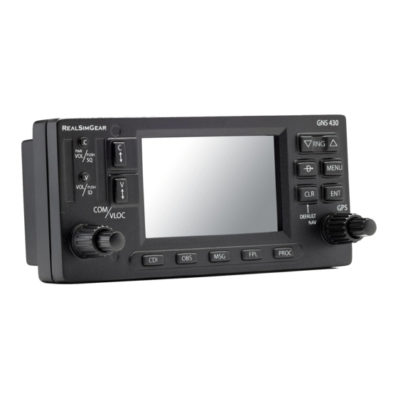
Garmin GNS 430 Pilot's Manual & Reference
Hide thumbs
Also See for GNS 430:
- Pilot's manual and reference (234 pages) ,
- Pilot's manual & reference (204 pages) ,
- Operating manual (27 pages)
Table of Contents
Advertisement
Advertisement
Table of Contents
Troubleshooting

Related Manuals for Garmin GNS 430


Summary of Contents for Garmin GNS 430
- Page 1 GNS 430(A) Pilot’s Guide and Reference...
- Page 3 Revision Date of Revision 12/98 4/99 6/99 7/99 4/00 7/00 5/03 5/06 6/06 2/07 10/07 05/08 08/08 12/09 190-00140-00 Rev. P Description Initial Release Update to conform to recent SW changes Added Addendum Update for SW 2.10 Update for SW 2.15 Updated Power On, Wind Vector, Crossfill, DME, and Fuel Plan Added FDE Section, updated per SW 5.01, misc.
- Page 4 Garmin® and AutoLocate® are registered trademarks of Garmin Ltd. or its subsidiaries and may not be used without the express permission of Garmin.
-
Page 5: Table Of Contents
SECTION 1: INTRODUCTION ... 1-1 1.1 Accessories and Packing List ... 1-1 1.2 Key and Knob Functions ... 1-2 1.3 Takeoff Tour ... 1-5 SECTION 2: COM ... 2-1 2.1 Communicating using the GNS 430 ... 2-1 SECTION 3: NAV PAGES ... - Page 6 Terrain data is obtained from third party sources. Garmin is not able to independently verify the accuracy of the terrain data.
- Page 7 CAUTION: The Garmin GNS 430 does not contain any user-serviceable parts. Repairs should only be made by an authorized Garmin service center. Unauthorized repairs or modifications could void both the warranty and the pilot’s authority to operate this device under FAA/FCC regulations.
- Page 8 Center; and 90 days for factory repaired or newly-overhauled products exchanged at Garmin in lieu of repair. Within the applicable period, Garmin will, at its sole option, repair or replace any components that fail in normal use. Such repairs or replacement will be made at no charge to the customer for parts or labor, provided that the customer shall be responsible for any transportation cost.
-
Page 9: Section 1: Introduction
The Garmin dealer installs and configures the GNS 430. The GNS 430 is secured in the installation rack with the proper wiring connections. A Garmin dealer can answer questions about the installation, such as location of antennas or any connections to other equipment in the panel. -
Page 10: Key And Knob Functions
SECTION 1 INTRODUCTION 1.2 KEy AND KNOB FUNCTIONS The GNS 430 is designed to make operation as simple as possible. The key and knob descriptions (Figure 1-1) provide a general overview of the primary function(s) for each key and knob. The takeoff tour (Section 1.3) is intended to provide a brief overview of the primary functions of the GNS 430. - Page 11 Left-hand Keys and Knobs (1) COM Power/Volume Knob – Controls unit power and communications radio volume. Press momentarily to disable automatic squelch control. (2) VLOC Volume Knob – Controls audio volume for the selected VOR/Localizer frequency. Press momentarily to enable/disable the ident tone. (3) COM Flip-flop Key –...
- Page 12 SECTION 1 INTRODUCTION NOTE: When the GNS 430 displays a list of information that is too long for the display screen, a scroll bar appears along the right-hand side of the display (Figure 1-2). The scroll bar graphically indicates the number of additional items available within the selected category.
-
Page 13: Takeoff Tour
Service staff is available during normal business hours (U.S. Central time zone) at the phone and fax numbers listed on page ii. Garmin can also be reached by mail (page ii) or at our website address, www.garmin.com. Powering up the GNS 430 The GNS 430’... - Page 14 SECTION 1 INTRODUCTION The Database Versions Page (Figure 1-4) appears next, which shows the current database information on the NavData and Terrain Data cards. information highlighted in yellow indicates the database is not within its effective dates. The NavData database is updated every 28 days and must be current for approved instrument approach operations.
- Page 15 Turn the small and large right knobs to enter the desired figure (Figures 1-5 and 1-6) and press the ENT Key. Figure 1-6 Fuel Flow Selected The Instrument Panel Self-test Page includes selections to set fuel on board (FOB) to full capacity and access the Checklists Page.
-
Page 16: Section 13: Fault Detection & Exclusion
SECTION 1 INTRODUCTION Satellite Status Page The Satellite Status Page (Figure 1-9) appears as the GNS 430 attempts to collect satellite information. When an ‘Acquiring’ status is displayed on the Satellite Status Page, the signal strengths of any satellites received appear as ‘bar graph’... - Page 17 Selecting COM and VLOC Frequencies While the GNS 430 is acquiring a position, take a minute to dial in the active and standby frequencies to be used for the first phase of the flight. The GNS 430’ s display is divided into separate windows (or screen areas), including a COM Window, VLOC Window, and the GPS Window (Figure 1-11).
- Page 18 SECTION 1 INTRODUCTION Page Groups Page Groups NAV Group WPT Group AUX Group NRST Group see Section 3 see Section 7 see Section 10 see Section 8 Table 1-1 Page Groups The bottom right corner of the screen (Figure 1-13) indicates which page group (Table 1-1) is currently being displayed, the number of pages available within that group (indicated by square icons), and the placement of the...
- Page 19 Map Page After the GNS 430 acquires satellites and computes a position, the Map Page (Figure 1-14) appears automatically. Map Display Desired Track Map Range Present Position Figure 1-14 Map Page The Map Page displays the present position (using an airplane symbol) relative to nearby airports, VORs, NDBs, intersections, user waypoints, and airspace boundaries.
- Page 20 SECTION 1 INTRODUCTION Press the ENT Key to confirm the identifier. The ‘Activate?’ function field is highlighted (Figure 1-16). Figure 1-16 ‘Activate?’ Highlighted Press the ENT Key to activate a direct-to course to the selected destination. Once a direct-to destination is selected, press and hold the CLR Key to display the Default NAV Page.
- Page 21 NAV/COM Page From the Default NAV Page, turn the small right knob until the NAV/COM Page (Figure 1-20) is displayed. Departure, Enroute, or Frequency List Arrival Airport Frequency Type Figure 1-20 NAV/COM Page The NAV/COM Page displays the available frequencies (communications and navigation) for the departure airport, any enroute airports which are included in the flight plan, and the final destination airport.
- Page 22 SECTION 1 INTRODUCTION To display frequencies for a different airport along the flight plan. Press the small right knob to highlight the airport identifier field. Turn the small right knob to display the list of airports within the flight plan (Figure 1-21). Figure 1-21 Airport Window Continue turning the small right knob to select the desired airport and press the ENT Key.
- Page 23 For approaches, a window appears (Figure 1-23) to select the desired initial approach fix (IAF) or provide a ‘vectors’ option to select just the final course segment of the approach. Turn the small right knob to select the desired option and press the ENT Key. (The ‘vectors’ option extends the final inbound course beyond the final approach fix, allowing the pilot to intercept the final course segment beyond its...
- Page 24 SECTION 1 INTRODUCTION To display the NRST pages: If necessary, press and hold the CLR Key to select the NAV group and display the Default NAV Page. Turn the large right knob to select the NRST Page Group, as indicated by ‘NRST’ appearing in the lower right corner of the screen.
- Page 25 To select a nearby airport as a direct-to destination from the Nearest Airport Page: From the Nearest Airport Page, press the small right knob to activate the cursor. Turn the large right knob to select the desired airport from the list. Press the Direct-to Key, the ENT Key twice to navigate to the nearby airport.
- Page 26 SECTION 1 INTRODUCTION By default, airspace alert messages are turned off. When turned on, the message (MSG) annunciator located directly above the MSG Key flashes to alert the pilot to the airspace message. See Section 10.4, Setup 1 Page: Airspace Alarms for information on enabling airspace alert messages.
- Page 27 Since using flight plans is arguably one of the more complex features of the GNS 430, it will be discussed only briefly here, with focus on creating a new flight plan and activating it to use for navigation. Answers to additional questions about flight plans not found in this brief introduction can be found in Section 5, Flight Plans.
- Page 28 SECTION 1 INTRODUCTION Blank Page 1-20 GNS 430(A) Pilot’s Guide and Reference 190-00140-00 Rev. P...
-
Page 29: Section 2: Com
SECTION 2: COM 2.1 COMMUNICATING USING THE GNS 430 The GNS 430 features a digitally-tuned VHF COM radio that provides a seamless transition from communication to navigation, bringing the two most important functions in flying together in one panel-mounted unit. The GNS 430’... - Page 30 SECTION 2 While receiving a station, an ‘RX’ indication (Figure 2-1) appears in the upper right corner of the COM Window to the immediate right of ‘COM’. A ‘TX’ indication appears at this location when transmitting (Figure 2-2). ‘TX’ Transmit Indication Figure 2-2 ‘TX’...
- Page 31 Auto-Tuning The GNS 430’ s auto-tune feature allows the pilot to quickly select any database frequency in the GPS Window as the standby frequency. Any COM frequency displayed in the GPS Window can be transferred to the standby COM frequency field, with a minimum of keystrokes required.
- Page 32 SECTION 2 To select a COM frequency for a nearby flight service station (FSS) or center (ARTCC): Turn the large right knob to select the NRST Page Group. Turn the small right knob to select the Nearest Center or Nearest Flight Service Page (Figure 2-7).
- Page 33 To select a COM frequency for any airport in the database: Turn the large right knob to select the WPT Page Group. Turn the small right knob to select the Airport Frequencies Page (Figure 2-9). Figure 2-9 Airport Frequencies Page Press the small right knob to place the cursor on the airport identifier field.
- Page 34 SECTION 2 Stuck Microphone As mentioned previously in this section, when the GNS 430 is transmitting, a ‘TX’ indication appears in the COM Window. If the microphone key is stuck or accidentally left in the on position; or the microphone continues to transmit after the key is released, the COM transmitter automatically times out (ceases transmitting) after 35 seconds of continuous broadcasting.
-
Page 35: Section 3: Nav Pages
SECTION 3: NAV PAGES 3.1 MAIN PAGE GROUPS The GNS 430’ s main pages are divided into four separate page groups: NAV, WPT, AUX, and NRST (Table 3-1). Each page group is comprised of multiple pages. The page groups are selected using the large right knob. -
Page 36: Default Nav Page
SECTION 3 NAV PAGES 3.3 DEFAULT NAV PAGE The first NAV page is the Default NAV Page (Figure 3-3). This page may be quickly selected from any page by pressing and holding the CLR Key. Active Leg of Flight Plan Course Deviation Indicator (CDI) TO/FROM Flag... - Page 37 Selecting Desired On-Screen Data At the bottom of the Default NAV Page there are six user-definable fields which display the data needed as the flight progresses (Figure 3-3). By default these fields display: distance to destination (DIS), desired track (DTK), bearing to destination (BRG), ground speed (GS), ground track (TRK), and estimated time enroute (ETE).
- Page 38 A ‘Crossfill?’ option is also provided for the Default NAV Page. This option transfers a direct-to destination or flight plan to a second Garmin 400 Series unit. See Section 10.2, Flight Planning: Crossfill for additional details on using the crossfill option.
-
Page 39: Map Page
3.4 MAP PAGE The second NAV page is the Map Page (Figure 3-8), which displays the present position using an airplane symbol, along with nearby airports, NAVAIDS, user- defined waypoints, airspace boundaries, lakes, rivers, highways, and cities. Present Map Display Data Fields Position Number of Pages in... - Page 40 SECTION 3 NAV PAGES To select a map range: Press the up arrow of the RNG Key to zoom out to a larger map area. Press the down arrow of the RNG Key to zoom in to a smaller map area and more detail. An autozoom feature is available which automatically adjusts from an enroute range of 2000 nm through each lower range, stopping at a range of 1.0 nm when...
- Page 41 Map Panning Another Map Page function is panning, which allows the map to move beyond its current limits without adjusting the map range. When the panning function is selected (by pressing the small right knob), a target pointer flashes on the Map Display (Figure 3-11).
- Page 42 SECTION 3 NAV PAGES Map Direct-to To designate an on-screen airport, NAVAID, or user waypoint as the direct-to destination: Use the panning function (‘Map Panning’ in this section) to place the target pointer on a waypoint. Press the Direct-to Key to display the select Direct-to Waypoint Page, with the selected waypoint already listed (Figure 3-13).
- Page 43 Press the ENT Key to display an options menu (Figure 3-15). Figure 3-15 Map Panning Options Window ‘Review Airspace?’ should already be highlighted. If not, select it with the small right knob. Press the ENT Key to display the Airspace Information Page for the selected airspace.
- Page 44 SECTION 3 NAV PAGES Table 3-4 lists the settings available for each group: Group Available Settings Orientation, AutoZoom, Land Data, Aviation Data Weather Lightning Mode/Symbol (when applicable) Traffic Traffic Mode/Symbol/Label (when applicable) Airport Large/Medium/Small Airports and Text NAVAID VORs, NDBs, Intersections, and Text Waypoint User Waypoints, Waypoint Text, Flight Plan Wpts...
- Page 45 Press the ENT Key to accept the selected option (Figure 3-19). Figure 3-19 Map Setup Page The automatic zoom feature automatically adjusts the map range from 2000 nm through each lower range, stopping at 1.0 nm when approaching the destination waypoint.
- Page 46 SECTION 3 NAV PAGES To display airspace boundaries, highways, roads, railroad lines, track log data, active flight plan course lines, and lat/long grid lines: From the Map Page Menu, turn the large right knob to highlight ‘Setup Map?’ and press the ENT Key.
- Page 47 To turn the data fields off/on: From the Map Page Menu, turn the large right knob to highlight ‘Data Fields Off?’ (or ‘Data Fields On?’) and press the ENT Key. Selecting Desired On-Screen Data ‘Change Fields?’ allows selection of the data displayed on the four user-selectable data fields along the right-hand side of the Map Page.
-
Page 48: Terrain Page
SECTION 3 NAV PAGES 3.5 TERRAIN PAGE NOTE: The TERRAIN Page does not appear on GNS 430 units that are not properly equipped with or configured for TERRAIN. See Section 11 for a full description of TERRAIN functions. TERRAIN Page To display the TERRAIN Page, select the NAV Page Group and turn the small right knob until the TERRAIN Page is displayed (Figure 3-26 and 3-27). - Page 49 To display a 360˚ view: Select the TERRAIN Page and press the MENU Key. Select ‘View 360˚?’ (Figure 3-28). Figure 3-28 TERRAIN Page Menu Press the ENT Key. To switch back to a 120˚ view, repeat step 1, select ‘View 120˚?, and press the ENT Key.
-
Page 50: Inhibit Mode
SECTION 3 NAV PAGES Inhibit Mode TERRAIN has an inhibit mode that deactivates the FLTA/PDA visual alerts. Pilots should use discretion when inhibiting TERRAIN and always remember to enable the system when appropriate. Only the PDA and FLTA alerts are disabled in the inhibit mode. See Section 11.3 for more information on TERRAIN alerts. -
Page 51: Nav/Com Page
3.6 NAV/COM PAGE The NAV/COM (navigation communications) Page (Figure 3-34) provides a list of the airport communication and navigation frequencies at the departure, enroute, and arrival airports. The NAV/COM Page makes selection of the frequencies needed along the flight plan quick and convenient. - Page 52 SECTION 3 NAV PAGES To scroll through the list of frequencies: Activate the cursor, if not already active, by pressing the small right knob. Turn the large right knob to move the cursor through the list of frequencies. If there are more frequencies in the list than can be displayed on the screen, a scroll bar along the right-hand side of the screen (Figure 3-36)
-
Page 53: Position Page
3.7 POSITION PAGE The Position Page displays the present position (by default, in latitude and longitude) and altitude. The Position Page (Figure 3-39) also displays the current track, ground speed, time, and a reference waypoint field. These fields are user-selectable to configure the page to the pilot’... - Page 54 SECTION 3 NAV PAGES Press the ENT Key to select the desired data item and return to the Position Page. Press the small right knob momentarily to remove the cursor from the page. The Position Page also features a reference waypoint field, located at the bottom of the page, to indicate bearing and distance to/from a selected waypoint.
- Page 55 Press the ENT Key to select the desired type and return to the Position Page. To select between ‘bearing FROM’ or ‘bearing TO’ to the reference waypoint, turn the small right knob to select the desired bearing reference (Figure 3-45) and press the ENT Key.
-
Page 56: Satellite Status Page
SECTION 3 NAV PAGES 3.8 SATELLITE STATUS PAGE The Satellite Status Page provides a visual reference of GPS receiver functions, including current satellite coverage, GPS receiver status, and position accuracy. The Satellite Status Page (Figure 3-47) is helpful in troubleshooting weak (or missing) signal levels due to poor satellite coverage or installation problems. - Page 57 Each satellite has a 30-second data transmission that must be collected (hollow signal strength bar, see Figure 3-47) before the satellite may be used for navigation (solid signal strength bar, see Figure 3-46). Once the GPS receiver has determined the present position, the GNS 430 indicates position, track, and ground speed on the other navigation pages.
-
Page 58: Vertical Navigation Page
SECTION 3 NAV PAGES 3.9 VERTICAL NAVIGATION PAGE The GNS 430’ s Vertical Navigation Page (the last NAV page, see Figure 3-49) creates a three-dimensional profile to provide guidance from the present position and altitude to a final (target) altitude at a specified location. This is helpful when descending to a certain altitude near an airport or climbing to an altitude before reaching a route or direct-to waypoint (Figure 3-50). - Page 59 Turn the small right knob to select ‘Above Wpt’ (AGL) or ‘MSL’, (Figure 3-52) and press the ENT Key. ‘Above Wpt’ uses the altitude of a destination airport as stored in the Jeppesen NavData Card. ‘MSL’ lets the pilot set a specific target altitude for any waypoint category: airport, VOR, NDB, intersection, or user waypoint.
- Page 60 SECTION 3 NAV PAGES With the profile set, the vertical speed required (VSR) is displayed on the Vertical Navigation Page. Expect the following to occur when using the vertical navigation feature: • At one minute prior to reaching the initial descent point, a message ‘Approaching VNAV Profile’...
-
Page 61: Section 4: Direct-To Navigation
SECTION 4: DIRECT-TO NAVIGATION 4.1 OVERVIEW The GNS 430’ s direct-to function provides a quick method of setting a course to a destination waypoint. Once a direct-to is activated, the GNS 430 establishes a point-to-point course line (great circle) from the present position to the selected direct-to destination. - Page 62 SECTION 4 DIRECT-TO NAVIGATION Selecting a Destination by Facility Name or City In addition to selecting a destination by identifier, the Select Direct-to Waypoint Page (Figure 4-4) also allows the pilot to select airports, VORs, and NDBs by facility name or city location.
- Page 63 To select a direct-to destination from the active flight plan: Press the Direct-to Key. The Select Direct-to Waypoint Page appears, with the waypoint identifier field highlighted. Turn the large right knob to highlight the flight plan (FPL) field (Figure 4-6). Figure 4-6 Highlighted Flight Plan Field Turn the small right knob to display a window showing all waypoints in the active flight plan...
- Page 64 SECTION 4 DIRECT-TO NAVIGATION Shortcuts Shortcuts are available when using the Direct-to Key, allowing the pilot to bypass the use of the small and large right knobs to enter the destination waypoint’ s identifier. A direct-to can be performed from any page displaying a single waypoint identifier (such as the WPT pages for airports and NAVAIDs).
- Page 65 Selecting a Direct-to destination from the Map Page Direct-to destinations may also be selected from the Map Page. If no airport, NAVAID, or user waypoint exists at the desired location, a waypoint named ‘+MAP’ is automatically created at the location of the panning pointer.
- Page 66 SECTION 4 DIRECT-TO NAVIGATION Specifying a Course to a Waypoint When performing a direct-to, the GNS 430 sets a direct great circle course to the selected destination. The course to the destination can also be manually defined using the ‘CRS’ course field on the Select Direct-to Waypoint Page. To manually define the direct-to course: Press the Direct-to Key.
-
Page 67: Section 5: Flight Plans
SECTION 5: FLIGHT PLANS The GNS 430 lets the pilot create up to 20 different flight plans, with up to 31 waypoints in each flight plan. The Flight Plan Page Group consists of two pages, (Active Flight Plan Page, Figure 5-1, and Flight Plan Catalog Page, Figure 5-2) accessed by pressing the FPL Key. - Page 68 SECTION 5 FLIGHT PLANS A blank Flight Plan Page appears for the first empty storage location (Figure 5-4). Use the small and large right knobs to enter the identifier of the departure waypoint and press the ENT Key. Figure 5-4 Flight Plan Page Repeat step 4 above to enter the identifier for each additional flight plan waypoint.
- Page 69 To delete a waypoint from an existing flight plan: Press the FPL Key and turn the small right knob to display the Flight Plan Catalog Page. Press the small right knob to activate the cursor. Turn the large right knob to highlight the desired flight plan and press the ENT Key.
- Page 70 SECTION 5 FLIGHT PLANS Activating Flight Plans Once a flight plan is defined through the Flight Plan Catalog Page (using the steps outlined previously in this section), it may be activated for navigation. Activating the flight plan places it into ‘flight plan 00’ and overwrites any previous information at that location.
- Page 71 Copying Flight Plans To save a flight plan currently located in ‘flight plan 00’, copy it to an open catalog location (1-19) before the flight plan is cancelled, overwritten, or erased. To copy a flight plan to another flight plan catalog location: From the Active Flight Plan Page, press the MENU Key to display the Active Flight Plan...
- Page 72 400-or 500-series Garmin unit. Some crossfill operations can be done automatically. If both units are set to ‘auto’, a change in the direct-to destination or active flight plan on one unit is seen on the other.
- Page 73 The ‘Cross-side’ field allows the pilot to designate the sending and receiving units in a crossfill operation. Turn the large right knob to select the ‘Cross-side’ field, then turn the small right knob to select ‘To’ or ‘From’ (Figure 5-15). Press the ENT Key to confirm the selection.
-
Page 74: Active Flight Plan Page
SECTION 5 FLIGHT PLANS • ‘Sort List By Number?’/’Sort List by Comment?’ - Allows the pilot to sort numerically by the flight plan number or sort alphanumerically based upon the comment assigned to each flight plan. When one option is selected, the other option appears on the Flight Plan Catalog Page Menu. - Page 75 Activate Leg which is currently used for navigation guidance). Allows the pilot to transfer the active flight plan between two 400- or 500-series Garmin units Crossfill in a dual unit installation. See Section 10.2, Flight Planning: Crossfill for additional information on this feature.
- Page 76 SECTION 5 FLIGHT PLANS The data fields for DTK and DIS are user-selectable and may be changed to display cumulative distance (CUM) to each waypoint, estimated time of arrival (ETA), estimated time enroute (ETE), or enroute safe altitude (ESA). To change a data field on the Active Flight Plan Page: With the Active Flight Plan Page displayed, press the MENU Key to display the Active Flight...
- Page 77 To select an approach for a direct-to or flight plan destination airport: Choose the ‘Select Approach?’ option from the Active Flight Plan Page Menu (Figure 5-24) and press the ENT Key. Figure 5-24 Active Flight Plan Page Menu A window appears listing the available approaches (Figure 5-25) for the destination airport.
- Page 78 SECTION 5 FLIGHT PLANS To select an arrival for a direct-to or flight plan destination airport: Select the ‘Select Arrival?’ option from the Active Flight Plan Page Menu (Figure 5-27) and press the ENT Key. Figure 5-27 Active Flight Plan Page Menu A window appears listing the available arrivals (Figure 5-28) for the destination airport.
- Page 79 To remove an approach, arrival, or departure from the active flight plan: Select the ‘Remove Approach?’, ‘Remove Arrival?’, or ‘Remove Departure?’ option from the Active Flight Plan Page Menu (Figure 5-30) and press the ENT Key. Figure 5-30 Active Flight Plan Page Menu A confirmation window appears listing the procedure to be removed.
- Page 80 SECTION 5 FLIGHT PLANS Shortcuts A number of shortcuts are available to save time when using the Active Flight Plan Page. These shortcuts speed the process of removing approaches, departures, and arrivals, and aid in selecting a specific flight plan leg for navigation guidance.
- Page 81 The ‘Activate Leg?’ option is discussed previously in this section, which allows the pilot to specify which leg of the flight plan is used for navigation guidance. A shortcut also exists for this operation, using the Direct-to Key. To activate a specific leg of the active flight plan: Press the small right knob to activate the cursor and turn the large right knob to...
- Page 82 SECTION 5 FLIGHT PLANS Blank Page 5-16 GNS 430(A) Pilot’s Guide and Reference 190-00140-00 Rev. P...
-
Page 83: Section 6: Procedures
SECTION 6: PROCEDURES 6.1 APPROACHES, DEPARTURES, AND ARRIVALS The GNS 430 allows the pilot to fly non-precision and precision approaches to airports with published instrument approach procedures. All available approaches are stored on the Jeppesen NavData Card, and are automatically updated when the new card is inserted into the GNS 430. - Page 84 SECTION 6 PROCEDURES Turn the large right knob to highlight ‘Load?’ or ‘Activate?’ (approaches only) and press the ENT Key. (‘Load?’ adds the procedure to the flight plan without immediately using it for navigation guidance. This allows the pilot to continue navigating the original flight plan, but keeps the procedure available on the Active Flight Plan Page for quick activation when...
- Page 85 Another Procedures Page option allows the pilot to activate the final course segment of the approach. This option assumes the pilot will receive vectors to the final approach fix (FAF) and provides guidance to intercept the final course, before reaching the FAF. To activate the approach, with vectors to final: Press the PROC Key to display the Procedures...
- Page 86 SECTION 6 PROCEDURES Select Destination ‘Select’ and ‘Load’ the approach ‘Activate’ the approach DO NOT USE FOR NAVIGATION Figure 6-7 Sample Approach Approach operations on the GNS 430 typically begin with the same basic steps (refer to Figure 6-7 for the following steps): Select the destination airport using the Direct- to Key, or as the last waypoint in the active...
- Page 87 The steps required to set up and fly the approach are detailed below (refer to Figure 6-8 for the following steps): Prior to departing KFDK, the destination (KLYH) is selected using the Direct-to Key or by creating a flight plan terminating at Lynchburg Regional.
- Page 88 SECTION 6 PROCEDURES Flying the Procedure Turn DO NOT USE FOR NAVIGATION Figure 6-12 Sample Approach with Procedure Turn Refer to Figure 6-12 for the following steps: Within 30 nm of the destination airport, the GNS 430 switches from ‘enroute’...
- Page 89 Figure 6-15 Waypoint Alert Fly the outbound course. Approximately one minute after passing the FAF (LYH), the alert message ‘START PROC TRN’ appears in the lower right corner of the screen. Initiate the procedure turn at any time after receiving this alert message. DO NOT USE FOR NAVIGATION ...
- Page 90 SECTION 6 PROCEDURES 11) After crossing the FAF, the destination sequences to the MAP (‘RW03’, the runway threshold, see Figure 6-18). Fly toward the MAP. Figure 6-18 Sequence to MAP NOTE: When viewing the Map Page, note that the final course segment is displayed in magenta (the active leg of the flight plan always appears in magenta) and a dashed line extends the course beyond the MAP.
- Page 91 Press the OBS Key. The missed approach holding point (MAHP; in this case ‘SWARM’ intersection) is automatically offered as the destination waypoint (Figure 6-21). Figure 6-21 Missed Approach Holding Point NOTE: In some cases, an additional hold waypoint is added to the missed approach sequence.
- Page 92 SECTION 6 PROCEDURES Flying an Approach with a Hold Starting where the previous example left off, assume weather conditions resulted in a missed approach at Lynchburg Regional. The pilot has decided to divert to Farmville Regional (KFVX) instead (refer to Figure 6-24 for the following steps).
- Page 93 Figure 6-28 Active Flight Plan Page Figure 6-29 Terminal Mode Refer to Figure 6-29 for the following steps. As in the last example, within 30 nm of the airport, the GNS 430 switches from enroute to terminal mode, and the CDI scale transitions from 5.0 to 1.0 nm, full scale deflection.
- Page 94 SECTION 6 PROCEDURES NOTE: If the pilot needs to lose extra altitude or speed by going around the holding pattern again, press the OBS Key to manually suspend waypoint sequencing before crossing the holding waypoint the second time. If this waypoint has already been passed, re-activate the holding pattern using the steps described in Section 5.2.
- Page 95 13) When approaching the FAF, a waypoint alert (‘NEXT DTK 209°’) appears in the lower right corner (Figure 6-34). Make any course adjustments necessary for the final course segment (FAF to MAP). Figure 6-34 Final Approach 14) After crossing the FAF, the destination sequences to the MAP (‘RW21’, the runway threshold).
- Page 96 SECTION 6 PROCEDURES Flying a DME Arc Approach The GPS overlay for a DME arc approach uses additional Jeppesen-provided waypoints to define the arc. These waypoints are indicated by ‘D’ as the first letter in the waypoint name. This is followed by three numbers which indicate the radial the waypoint lies on.
- Page 97 Figure 6-39 Approach Window DO NOT USE FOR NAVIGATION Billard Muni (Topeka, KS) VOR or GPS Rwy 22 Figure 6-40 Terminal Mode Refer to Figure 6-40 for the following steps. Within 30 nm of KTOP, the GNS 430 switches from enroute mode to terminal mode and the CDI scale transitions from 5.0 to 1.0 nm, full scale deflection.
- Page 98 SECTION 6 PROCEDURES The next point in the approach is an intermediate fix, labeled ‘D025G’. When approaching this intermediate fix, a waypoint alert (‘NEXT DTK 205°’) appears in the lower right corner of the screen (Figure 6-43). As the distance to this fix approaches zero, the alert is replaced by a turn advisory (‘TURN TO 205°’).
- Page 99 10) After crossing the FAF, the destination sequences to the MAP (‘RW22’, the runway threshold). With the needle centered, fly toward the MAP, observing the altitude minimums dictated by the approach plate. When viewing the Map Page, note that the final course segment is displayed in magenta (the active leg of the flight plan always appears in magenta) and a dashed line extends the course...
- Page 100 SECTION 6 PROCEDURES To select ‘VECTORS’ from the Transitions Window: Select Billard Municipal (KTOP) as the destination, using the Direct-to Key, or as the last waypoint in a flight plan. Press the PROC Key and select the ‘VOR 22’ approach using the steps outlined in Section 6.1.
- Page 101 DO NOT USE FOR NAVIGATION Figure 6-51 Terminal Mode In this example, assume ATC vectors result in a rectangular course to intercept final, as follows (refer to Figure 6-51 for the following steps): Within 30 nm of KTOP, the GNS 430 switches from enroute mode to terminal mode and the CDI scale transitions from 5.0 to 1.0 nm, full scale deflection.
- Page 102 SECTION 6 PROCEDURES DO NOT USE FOR NAVIGATION Figure 6-55 Approach Mode Refer to Figure 6-55 for the following steps. At 2.0 nm from the FAF (TOP VOR), the GNS 430 switches from terminal mode to approach mode (Figure 6-56).
- Page 103 Course From Fix Flight Plan Legs Certain approach, departure, and arrival procedures in the Jeppesen database contain course from fix flight plan legs. The GNS 430 is able to load these legs into the flight plan along with the rest of the procedure data, and provide navigation along these legs.
- Page 104 SECTION 6 PROCEDURES At 13.0 nm from the FAF, a waypoint alert (‘NEXT DTK 265°’) appears in the lower right corner of the screen. Turn to intercept the final approach course and watch for the CDI needle to begin to center. When approaching the intermediate fix (CF25), a waypoint alert (‘NEXT DTK 265°’) appears.
- Page 105 MISSED APPROACH: Palmdale (CA) AF Plant 42 VOR/DME or GPS Rwy 25 DO NOT USE FOR NAVIGATION MISSED APPROACH Climb to 5000’ outbound via PMD VOR R-282, then climbing RIGHT turn to 7000’ direct PMD VOR and hold. Figure 6-65 Palmdale Missed Approach In this instance, the leg corresponds to the initial phase of the missed approach, which reads ‘Climb to 5000’...
- Page 106 SECTION 6 PROCEDURES When approaching PMD VOR (the missed approach holding point), an alert message in the lower right-hand corner of the screen recommends the holding pattern entry procedure (‘HOLD PARALLEL’). When flying the holding pattern, a timer appears on the Default NAV Page.
- Page 107 Refer to Figure 6-68 for the following steps. Select the departure (CSTL1) from the Procedures Page, then select the departure runway, (RW02 in this example, see Figure 6-69) and transition (GEDIC). Refer to Section 6.1 for instructions on selecting departures. Figure 6-69 Runway Window When departing the airfield, ‘NEXT DTK 026°’...
-
Page 108: Ils Approaches
SECTION 6 PROCEDURES 6.3 ILS APPROACHES Precision approaches can be performed with the GNS 430’ s built-in VLOC (VOR/localizer/glideslope) receivers. The GPS receiver can be used for guidance prior to reaching the final approach fix, but once there, the proper frequency must be selected on the VLOC Window (left side of screen) and the CDI output set to ‘VLOC’. - Page 109 The automatic switch from GPS to VLOC occurs gradually to prevent abrupt CDI changes when coupled to an autopilot. The CDI selection can also be changed manually by pressing the CDI Key. Once the switch from GPS to VLOC has occurred, either automatically or manually, it does not automatically switch again until the approach is reactivated or another approach is selected.
- Page 110 SECTION 6 PROCEDURES Press the PROC Key and select the ‘ILS 21’ approach (Figure 6-75) using the steps outlined in Section 6.1. Figure 6-75 Approach Window From the Transitions Window, select ‘SHUTR’ as the IAF (Figure 6-76). Also, select ‘Load?’ (or ‘Activate?’, if already cleared for the approach).
- Page 111 Within 30 nm of KFLG, the GNS 430 switches from enroute mode to terminal mode and the CDI scale transitions from 5.0 to 1.0 nm, full scale deflection. If the approach has not yet been activated, (in steps on the preceding page), do so when cleared for the approach (Figure 6-78).
- Page 112 SECTION 6 PROCEDURES DO NOT USE FOR NAVIGATION Figure 6-82 ILS Approach Course Refer to Figure 6-82 for the following steps. Initiate the procedure turn. The GNS 430 does not provide guidance through the turn. (The procedure turn is displayed on the Map Page and indicated as the active leg on the Default NAV Page and the Active Flight Plan Page.) After approximately one minute, make a turn...
- Page 113 DO NOT USE FOR NAVIGATION Figure 6-85 Final Approach, Flagstaff Refer to Figure 6-85 for the following steps. 12) When approaching SHUTR, a waypoint alert (‘NEXT DTK 210°’) appears in the lower right corner of the screen (Figure 6-84). 13) After crossing SHUTR, the destination sequences to the MAP (‘RW21’, the runway threshold, see Figure 6-86).
- Page 114 SECTION 6 PROCEDURES 15) After crossing the MAP, ‘SUSP’ appears above the OBS Key (Figure 6-88), indicating that automatic sequencing of approach waypoints is suspended at the MAP. A ‘FROM’ indication is displayed on the CDI and Default NAV Page, but course guidance along the final approach course continues.
- Page 115 Points to Remember for Localizer-based Approaches • The default factory setting allows the CDI output to automatically switch from the GPS receiver to the VLOC receiver. If the ‘ILS CDI Capture’ setting is changed to ‘Manual’, the pilot must determine when to select GPS or VLOC guidance during the approach.
- Page 116 SECTION 6 PROCEDURES Blank Page 6-34 GNS 430(A) Pilot’s Guide and Reference 190-00140-00 Rev. P...
-
Page 117: Section 7: Wpt Pages
SECTION 7: WPT PAGES 7.1 WPT PAGE GROUP Section 3.1 introduced the GNS 430’ s main page groups (Table 7-1)—NAV, WPT, AUX, NRST—and described each page in the NAV group. This second page group (WPT) provides information for the thousands of airports, VORs, NDBs, intersections, runways, frequencies, and procedures stored on the Jeppesen NavData Card. - Page 118 SECTION 7 WPT PAGES To enter a waypoint identifier: Select the desired WPT page and press the small right knob to activate the cursor. Turn the small right knob to select the first character of the waypoint’s identifier. Turn the large right knob to select the next character field.
- Page 119 Duplicate Waypoints Once the identifier, facility name, or location is entered, all six airport pages display information for the selected airport. When entering an identifier, facility name, or location, the GNS 430’ s Spell’N’Find feature scrolls through the database, displaying those waypoints matching the characters that have been entered to that point.
-
Page 120: Airport Location Page
SECTION 7 WPT PAGES 7.2 AIRPORT LOCATION PAGE The Airport Location Page (Figure 7-8) displays the latitude, longitude, and elevation of the selected airport. The Airport Location Page also displays facility name and location, as well as fuel availability, available approaches, radar coverage, and airspace type. -
Page 121: Airport Runway Page
7.3 AIRPORT RUNWAy PAGE The Airport Runway Page (Figure 7-9) displays runway designations, length, surface type, and lighting for the selected airport. A map image of the runway layout and surrounding area is also displayed on the Airport Runway Page. The map image range appears in the lower left corner and is adjustable using the RNG Key. -
Page 122: Airport Frequency Page
SECTION 7 WPT PAGES To adjust the range of the map image: Press the down arrow of the RNG Key to display a smaller map area. Press the up arrow of the RNG Key to display a larger map area. The following descriptions and abbreviations are used on the Airport Runway Page: •... - Page 123 Turn the large right knob to scroll through the list, placing the cursor on the desired frequency (Figure 7-13). If there are more frequencies in the list than can be displayed on the screen, a scroll bar (Figure 7-12) along the right-hand side of the screen indicates the cursor’s position within the list.
-
Page 124: Airport Approach Page
SECTION 7 WPT PAGES The following descriptions and abbreviations are used on the Airport Frequency Page: • Type - Usage type: Public, Heliport, Military, or Private • Frequency - Communication frequencies which may include restrictions: Approach Arrival Class C Terminal Communication frequencies without restrictions: ATIS ASOS... - Page 125 Turn the small right knob to display a window of available approaches for the selected airport (Figure 7-18). Continue turning the small right knob to select the desired approach. Figure 7-18 Approach Window Press the ENT Key. The cursor moves to the transitions (TRANS) field.
- Page 126 SECTION 7 WPT PAGES Airport Approach Page Options The following options are available for the Airport Approach Page, by pressing the MENU Key: ‘Load into Active FPL?’ allows the pilot to load the selected approach into the active flight plan without activating it.
-
Page 127: Airport Arrival Page
7.6 AIRPORT ARRIVAL PAGE The Airport Arrival Page (Figure 7-22) shows the available Airport Standard Terminal Arrival (STAR) procedures for the selected airport. Where multiple transitions or runways are associated with the arrival procedure, that information may also be displayed. A map image provides a layout diagram for each arrival, transition, and runway. - Page 128 SECTION 7 WPT PAGES Turn the small right knob to display a window of available runways (Figure 7-25). Continue turning the small right knob to select the desired runway. (‘ALL’ may appear in the runway field, indicating the arrival procedure applies to all runways.
-
Page 129: Airport Departure Page
7.7 AIRPORT DEPARTURE PAGE The Airport Departure Page (Figure 7-27) shows the available Airport Standard Instrument Departure (SID) procedures for the selected airport. Where multiple runways or transitions are associated with the departure procedure, that information may also be displayed. A map image provides a layout diagram for each departure, runway, and transition. -
Page 130: Intersection Page
SECTION 7 WPT PAGES Airport Departure Page Options The following option is available for the Airport Departure Page, by pressing the MENU Key: ‘Load into Active FPL?’ allows the pilot to load the selected departure into the active flight plan. This is identical to loading a departure procedure from the Procedures Page, as described in Section 6.1. -
Page 131: Ndb Page
7.9 NDB PAGE The NDB Page displays the facility name, city, region/country, latitude, and longitude for the selected NDB (Figure 7-32). The NDB Page also displays the frequency and a weather broadcast indication (if applicable). As mentioned in Section 7.1, NDBs may be selected by identifier, facility name, or location (city). - Page 132 SECTION 7 WPT PAGES To select a VOR frequency from the VOR Page: Select the VOR Page from the WPT Page Group, as described in Section 7.1. Press the small right knob momentarily to place the cursor on the VOR identifier field (Figure 7-34).
-
Page 133: Creating User Waypoints
7.11 USER WAyPOINT PAGE In addition to the airport, VOR, NDB, and intersection information contained in the Jeppesen NavData Card, the GNS 430 allows the pilot to store up to 1,000 user- defined waypoints. The User Waypoint Page (Figure 7-37) displays the waypoint name (up to five characters long), identifier, radial from two reference waypoints, and distance from one reference waypoint, along with the user waypoint’... - Page 134 SECTION 7 WPT PAGES Turn the large right knob to highlight the position field at the bottom of the page. Use the small and large right knobs to enter the position coordinates for the new waypoint (Figure 7-40). Figure 7-40 Present Position Field Selected Press the ENT Key to accept the selected position.
-
Page 135: Capture And Save Present Position
Turn the large right knob to highlight ‘Create?’ (Figure 7-42) and press the ENT Key. Figure 7-42 ‘Create?’ Highlighted Press the small right knob to remove the flashing cursor. NOTE: The GNS 430 allows the pilot to create a new user waypoint at a defined radial and distance from the present position. -
Page 136: Modifying User Waypoints
SECTION 7 WPT PAGES Press the ENT Key to capture the position and display the User Waypoint Page (Figure 7-44). Figure 7-44 User Waypoint Page A four-digit name is automatically assigned to the waypoint. To change this name, turn the large right knob to highlight the name field, then use the small and large right knobs to select a new name. - Page 137 To modify a user waypoint by changing reference waypoint information: With the User Waypoint Page displayed, press the small right knob to activate the cursor. Use the small and large right knobs to enter the name of the desired waypoint and press the ENT Key.
- Page 138 SECTION 7 WPT PAGES User Waypoint Page Options The following User Waypoint Page options are available by pressing the MENU Key: ‘View User Waypoint List?’ displays a list of all user waypoints currently stored in memory. To view a list of all user waypoints: From the User Waypoint Page, press the MENU Key to display the User Waypoint Page Menu.
- Page 139 User Waypoint List The User Waypoint List (Figure 7-52) allows the pilot to review, modify, rename, or delete a selected user waypoint, or to delete all user waypoints currently stored in memory. The top of the page shows the number of waypoints used and available memory.
- Page 140 SECTION 7 WPT PAGES To delete a user waypoint from the User Waypoint List: Select the User Waypoint List, as described in this section. Turn the large right knob to highlight the desired user waypoint. Press the CLR Key to display a ‘delete waypoint’ confirmation window (Figure 7-55).
-
Page 141: Section 8: Nrst Pages
SECTION 8: NRST PAGES 8.1 NRST PAGE GROUP Section 3.1 introduced the GNS 430’ s main page groups (Table 8-1)—NAV, WPT, AUX, NRST—and described each page in the NAV group. This fourth page group (NRST) provides detailed information for the nine nearest airports, VORs, NDBs, intersections, and user waypoints within 200 nm of the current position. - Page 142 SECTION 8 NRST PAGES Not all nine nearest airports, VORs, NDBs, intersections, or user waypoints can be displayed on the corresponding NRST page at one time. The Nearest Airport Page displays detailed information for three nearest airports, with a scroll bar along the right-hand side of the page indicating which part of the list is currently being viewed.
- Page 143 Navigating to a Nearby Waypoint The NRST pages can be used in conjunction with the GNS 430’ s direct-to function to quickly set a course to a nearby facility and can provide navigation to the nearest airport in case of an in-flight emergency. To select a nearby airport, VOR, NDB, intersection, or user waypoint as a direct- to destination:...
-
Page 144: Nearest Airport Page
SECTION 8 NRST PAGES 8.2 NEAREST AIRPORT PAGE The Nearest Airport Page displays the identifier, symbol, bearing, and distance to the nine nearest airports (within 200 nm of the present position). For each airport listed, the Nearest Airport Page also indicates the best available approach, common traffic advisory frequency (CTAF), and the length of the longest runway (Figure 8-9). - Page 145 Press the COM Flip-flop Key to activate the selected frequency (Figure 8-12). Figure 8-12 Frequency Moved to Active Field Press the small right knob to remove the flashing cursor. Additional communication frequencies, runway infor- mation, and more is available from the Nearest Airport Page by highlighting the identifier of the desired airport and pressing the ENT Key.
-
Page 146: Nearest Intersection Page
SECTION 8 NRST PAGES 8.3 NEAREST INTERSECTION PAGE The Nearest Intersection Page (Figure 8-16) displays the identifier, symbol, bearing, and distance to the nine nearest intersections (within 200 nm of the present position). To view additional information for a nearby intersection, start from the Nearest Intersection Page and follow the preceding steps 2 through 4. -
Page 147: Nearest Vor Page
8.5 NEAREST VOR PAGE The Nearest VOR Page (Figure 8-18) displays the identifier, symbol, bearing, and distance to the nine nearest VORs (within 200 nm of the present position). For each VOR listed, the nearest VOR Page also indicates the frequency and may be used to quickly tune the VLOC receiver to the nearby VOR. -
Page 148: Nearest User Waypoint Page
SECTION 8 NRST PAGES To view additional information for a nearby VOR: Select the nearest VOR Page, using the steps outlined in Section 8.1. Press the small right knob to activate the cursor. Turn the large right knob to scroll through the list, highlighting the identifier of the desired VOR (Figure 8-20). -
Page 149: Nearest Center (Artcc) Page
8.7 NEAREST CENTER (ARTCC) PAGE The Nearest Center Page (Figure 8-22) displays the facility name, bearing to, and distance to the five nearest ARTCC points of communication (within 200 nm of the present position). For each ARTCC listed, the Nearest Center Page also indicates the frequency(ies) and may be used to quickly tune the COM transceiver to the center’... -
Page 150: Nearest Flight Service Station (Fss) Page
SECTION 8 NRST PAGES 8.8 NEAREST FLIGHT SERVICE STATION (FSS) PAGE The Nearest Flight Service Station Page (Figure 8-25) displays the facility name, bearing to, and distance to the five nearest FSS points of communication (within 200 nm of the present position). For each FSS listed, the Nearest Flight Service Station Page also indicates the frequency(ies) and may be used to quickly tune the COM transceiver to the FSS’... -
Page 151: Nearest Airspace Page
Press the ENT Key to place the selected frequency in the standby field of the COM or VLOC Window (figure 8-28). Figure 8-28 Frequency Moved to Standby Field Press the COM Flip-flop or VLOC Flip-flop Key, as appropriate, to activate the selected frequency. - Page 152 SECTION 8 NRST PAGES • If the aircraft has entered an airspace, the message ‘Inside Airspace’ appears (Figure 8-30). The Nearest Airspace Page shows ‘Inside of airspace’. Figure 8-30 Airspace Messages Note that the airspace alerts are based on three- dimensional data (latitude, longitude, and altitude) to avoid nuisance alerts.
- Page 153 Turn the large right knob to scroll through the list, highlighting the desired airspace (Figure 8-33). Figure 8-33 Airspace Highlighted Press the ENT Key to display the Airspace Page for the selected nearby airspace (Figure 8-34). Airspace Name Status and Floor/Ceiling and Type Time to Entry...
- Page 154 SECTION 8 NRST PAGES To return to the Airspace Page, turn the large right knob to highlight ‘Done?’ and press the ENT Key (or press the CLR Key). To return to the Nearest Airspace Page, turn the large right knob to highlight ‘Done?’ and press the ENT Key (or press the CLR Key).
-
Page 155: Section 9: Vloc Receiver
SECTION 9: VLOC RECEIVER 9.1 VLOC (VOR/LOCALIZER/GLIDESLOPE) RECEIVER OPERATIONS The GNS 430 includes digitally-tuned VOR/localizer and glideslope receivers with the desired frequency selected in the VLOC Window, along the left-hand side of the display (Figure 9-1). Frequency selection is performed by pressing the small left knob and turning the small and large left knobs to select the desired frequency. - Page 156 SECTION 9 VLOC RECEIVER Turn the large left knob to select the desired megahertz (MHz) value. For example, the ‘117’ portion of the frequency ‘117.60’ (Figure 9-3). Figure 9-3 Select VOR Megahertz Frequency Turn the small left knob to select the desired kilohertz (kHz) value.
- Page 157 Press the ENT Key to place the frequency in the standby field of the VLOC Window (Figure 9-6). Figure 9-6 Frequency in Standby Field Press the VLOC Flip-flop Key to activate the selected frequency. Press the small right knob to remove the flashing cursor.
- Page 158 SECTION 9 VLOC RECEIVER Turn the large right knob to highlight ‘Load?’ or ‘Activate?’ (Figure 9-8) and press the ENT Key. (‘Load?’ adds the procedure to the flight plan without immediately using it for navigation guidance. This allows the pilot to continue navigating the original flight plan, but keeps the procedure available on the Active Flight Plan Page for quick activation when...
-
Page 159: Section 10: Aux Pages
SECTION 10: AUX PAGES 10.1 AUX PAGE GROUP Section 3.1 introduced the GNS 430’ s main page groups (Table 10-1)—NAV, WPT, AUX, NRST—and described each page in the NAV group. The third page group (AUX) allows the pilot to change unit settings. The AUX pages (Figure 10-1) also provide E6B functions, such as trip planning, fuel planning, density altitude, true airspeed, and winds aloft calculations. -
Page 160: Flight Planning Page
SECTION 10 AUX PAGES 10.2 FLIGHT PLANNING PAGE The Flight Planning Page (Figure 10-4) provides access (via menu options) to E6B functions for fuel planning, trip planning, density altitude/true airspeed/winds aloft calculations and a ‘Crossfill’ function to transfer flight plans/user waypoints to a second GNS 430. When a menu option is selected, the corresponding page appears providing additional information and features. - Page 161 • Crossfill - Allows the pilot to transfer the active flight plan, any stored flight plan, a user waypoint, or all user waypoints between two 400/500-series Garmin units in a dual-unit installation. See Section 5.1, Flight Plan Catalog Options and information following in this section for details.
- Page 162 SECTION 10 AUX PAGES Flight Planning Page: Fuel Planning To perform fuel planning operations: Select ‘Fuel Planning’ from the Flight Planning Page, using the steps described in Section 10.2. The current fuel planning ‘mode’ is displayed at the top of the page (Figure 10-7): ‘POINT TO POINT’...
- Page 163 If the fuel management system does not enter the data automatically, turn the large right knob to highlight the fuel on board (FOB) field (Figure 10-11). Figure 10-11 FOB Highlighted Use the small and large right knobs to enter the amount of fuel on board. Press the ENT Key when finished.
- Page 164 SECTION 10 AUX PAGES Fuel planning figures can be entered and displayed based upon one of three possible configurations: • No fuel sensors connected - In this instance fuel flow is manually entered and is used to calculate fuel on board. When fuel flow or fuel on board is manually entered, the figures are retained the next time the page is displayed (with fuel on board continuously recalculated).
- Page 165 Turn the large right knob to highlight the departure time (DEP TIME) field. Use the small and large right knobs to enter the departure time. Press the ENT Key when finished. (Departure time may be entered in local or UTC time, depending upon unit settings, see Section 10.4, Setup 1 Page: Date/ Time.) The flashing cursor moves to the ground speed...
- Page 166 SECTION 10 AUX PAGES The flashing cursor moves to the barometric pressure (BARO) field. Use the small and large right knobs to enter the barometric pressure (altimeter setting). Press the ENT Key when finished. The flashing cursor moves to the total air temperature (TAT) field.
- Page 167 ‘Manual’ (Figure 10-23). ‘Auto’ automatically transfers any selection of (or any change to) a direct-to destination or active flight plan to a second 400/500 series Garmin unit. 190-00140-00 Rev. P Figure 10-23 Crossfill Method Window NOTE: Crossfill requires both 400 and/or 500 Series units to have the same Jeppesen NavData database cycle number.
- Page 168 SECTION 10 AUX PAGES • Active Flight Plan - Transfer the active flight plan to/from a second 400/500-series Garmin unit in a dual unit installation. This option is the default when selecting ‘Crossfill’ from the Active Flight Plan Page. • Flight Plan - Transfer any stored flight plan to/from a second 400/500-series unit, by selecting the flight plan by number.
- Page 169 The flashing cursor moves to the type field under the new message (Figure 10-27). Turn the small right knob to display a window of available options, (Figure 10-28): Event, One Time, Periodic. Press the ENT Key to select. Figure 10-27 Type Field Highlighted Figure 10-28 Type Window The flashing cursor moves to the time/date field.
-
Page 170: Utility Page
SECTION 10 AUX PAGES 10.3 UTILITy PAGE The Utility Page (Figure 10-29) provides access (via ‘menu options’) to checklists, a count down/up timer, trip timers, trip statistics, RAIM (Receiver Autonomous Integrity Monitoring) prediction, sunrise/sunset time calculations, software versions, database versions, and terrain database version information. - Page 171 • RAIM Prediction - Predicts if GPS coverage is available for the current location or at a specified waypoint at any time and date. Receiver Autonomous Integrity Monitoring (RAIM) performs checks to ensure that the GNS 430 will have adequate satellite geometry during the flight.
- Page 172 SECTION 10 AUX PAGES Utility Page: Checklists To create a checklist: Select ‘Checklist’ from the Utility Page (Figure 10-33), using the steps described at the beginning of this section (10.3). Press the ENT Key to display a list of checklists. Figure 10-33 Checklists Highlighted Press the MENU Key to display an options menu.
- Page 173 To insert a checklist step into an existing checklist: With the Checklists Page displayed, turn the large right knob to select the desired checklist and press the ENT Key. Turn the large right knob to highlight the existing checklist entry which immediately follows the new checklist step.
- Page 174 SECTION 10 AUX PAGES For a count down timer, turn the large right knob to highlight the time field. Use the small and large right knobs to enter the count down time—in hours, minutes, and seconds. Press the ENT Key when finished. To stop the generic timer, turn the large right knob to highlight ‘Stop?’...
- Page 175 Utility Page: Trip Statistics To reset trip statistics readouts: Select ‘Trip Statistics’ from the Utility Page (Figure 10-40), using the steps described at the beginning of this section. Figure 10-40 Trip Statistics Highlighted Press the MENU Key to display the Trip Statistics Page Menu with several reset options (Figure 10-41): Figure 10-41 Trip Statistics Page Menu...
- Page 176 SECTION 10 AUX PAGES The flashing cursor moves to the arrival date field. Use the small and large right knobs to enter the date for which the pilot wants to determine RAIM availability. Press the ENT Key when finished. The flashing cursor moves to the arrival time field.
- Page 177 Press the ENT Key to calculate sunrise and sunset times for the selected location and date (Figure 10-47). Figure 10-47 Sunrise/Sunset Page Utility Page: Software Versions The Software Versions Page (Figure 10-48) displays software version information for each of the various subsystems contained within the GNS 430.
-
Page 178: Setup 1 Page
SECTION 10 AUX PAGES 10.4 SETUP 1 PAGE The Setup 1 Page (Figure 10-51) provides access (via menu options) to airspace alarms, CDI scale adjustment, an arrival alarm, units of measure settings, position formats, map datums, and settings for local or UTC time display. When a menu option is selected, the corresponding page appears providing access to the various unit settings. - Page 179 CDI Scales and Corresponding Flight Phases: Oceanic Enroute Terminal Approach Figure 10-54 CDI Scales During approach operations the CDI scale gradually ramps down even further, to 0.3 nm. This transition normally occurs within 2.0 nm of the final approach fix (FAF). If a lower CDI scale setting is selected (i.e., 1.0 nm or 0.3 nm) the higher scale settings are not selected during any phase of flight.
- Page 180 SECTION 10 AUX PAGES • ‘Position/Map Datum’ - Configures position readout information to the desired position format. The GNS 430 uses the map datum WGS 84. Note that using a map datum that does not match the charts used by the pilot can result in significant differences in position information.
- Page 181 Setup 1 Page: CDI Scale/Alarms To change the CDI scale: Select ‘CDI/Alarms’ from the Setup 1 Page (Figure 10-58), using the steps described at the beginning of this section. Figure 10-58 CDI/Alarms Highlighted The flashing cursor highlights the ‘Selected CDI’ field.
- Page 182 SECTION 10 AUX PAGES To set the arrival alarm and alarm distance: Select ‘CDI/Alarms’ from the Setup 1 Page, using the steps described at the beginning of this section. Turn the large right knob to highlight the ‘On’/’Off’ field (directly below ‘Arrival Alarm’). Turn the small right knob to select ‘On’...
- Page 183 Figure 10-63 Units Mag/Var Page The following categories, and corresponding units of measure, are available: • DIS, SPD - Distance and speed in Nautical (nautical miles/knots), Statute (miles/miles per hour), or Metric (kilometers/kilometers per hour) terms • ALT, VS - Altitude and vertical speed in Feet/feet per minute, Meters/meters per minute, or Meters/ meters per second •...
- Page 184 SECTION 10 AUX PAGES To display the map datum: Select ‘Position Format/Map Datum’ from the Setup 1 Page, using the steps described at the beginning of this section. The WGS 84 map datum is displayed, this field cannot be changed. Figure 10-66 WGS 84 Map Datum Setup 1 Page: Date/Time To display local time or UTC:...
-
Page 185: Setup 2 Page
Restoring Factory Settings When making changes to any Setup 1 Page option, a ‘Restore Defaults?’ menu selection allows the pilot to restore the original factory settings (for the selected option only). For example, with the Airspace Alarms Page displayed, the ‘Restore Defaults?’ option restores all Airspace Alarms Page settings to the original factory values. - Page 186 SECTION 10 AUX PAGES Turn the large right knob to select the desired menu option (Figure 10-71), and press the ENT Key (Figure 10-72). Figure 10-71 Nearest Airport Criteria Highlighted Figure 10-72 Nearest Airport Criteria Page The following menu options are available: •...
- Page 187 Figure 10-74 Backlight Mode Window If ‘Manual’ is selected, the flashing cursor moves to the backlight level field. Turn the small right knob to select the desired level. Press the ENT Key to accept the selection. To change the display contrast: Select ‘Display’...
- Page 188 SECTION 10 AUX PAGES The flashing cursor moves to the minimum runway length field (Figure 10-77). To enter a different minimum runway length, use the small and large right knobs to enter the desired length. Press the ENT Key when finished.
-
Page 189: Section 11: Terrain
TERRAIN uses terrain and obstacle information supplied by government sources. The data undergoes verification by Garmin to confirm accuracy of the content, per TSO-C151b. However, the displayed information should never be understood as being all-inclusive. GNS 430(A) Pilot’s Guide and Reference... - Page 190 SECTION 11 TERRAIN TERRAIN Alerting TERRAIN uses information provided from the GPS receiver to provide a horizontal position and altitude. GPS altitude is derived from satellite measurements. GPS altitude is converted to a mean sea level (MSL)-based altitude (GPS-MSL altitude) and is used to determine TERRAIN alerts.
- Page 191 11.2 TERRAIN PAGE See Section 3.5 for a complete description of the TERRAIN Page and its operation. TERRAIN Symbols The symbols and colors in Figure 11-1 and Table 11-1 are used to represent obstacles and potential impact points on the TERRAIN Page. TERRAIN uses yellow (caution) and red (warning) to depict terrain information relative to aircraft altitude.
-
Page 192: Terrain Alerts
SECTION 11 TERRAIN 11.3 TERRAIN ALERTS TERRAIN Alerts are issued when flight conditions meet parameters that are set within TERRAIN software algorithms. TERRAIN alerts typically employ either an ADVISORY or a CAUTION alert severity level, or both. When an alert is issued, visual annunciations are displayed. - Page 193 Table 11-2 shows the possible TERRAIN alert types with corresponding annunciations. Alert Type TERRAIN Failure TERRAIN Inhibited TERRAIN Not Available Required Terrain Clearance (RTC) Advisory Required Terrain Clearance (RTC) Caution Imminent Terrain Impact (ITI) Advisory Imminent Terrain Impact (ITI) Caution Required Obstacle Clearance (ROC) Advisory Required Obstacle Clearance (ROC) Caution Imminent Obstacle Impact (IOI) Advisory...
- Page 194 SECTION 11 TERRAIN Table 11-3 shows system status annunciations that may also be issued: Alert Type TERRAIN System Test Fail TERRAIN Alerting is disabled No GPS position or excessively degraded GPS signal System Test in progress System Test pass Forward Looking Terrain Avoidance The Forward Looking Terrain Avoidance (FLTA) alert is used by TERRAIN and is composed of: •...
- Page 195 Premature Descent Alerting A Premature Descent Alert (PDA) is issued when the system detects that the aircraft is significantly below the normal approach path to a runway (Figure 11-5). PDA alerting begins when the aircraft is within 15 nm of the destination airport. PDA alerting ends when the aircraft is either: •...
- Page 196 SECTION 11 TERRAIN TERRAIN NOT AVAILABLE ALERT TERRAIN requires a 3-D GPS navigation solution along with specific vertical accuracy minimums. Should the navigation solution become degraded or if the aircraft is out of the database coverage area, the annunciation ‘TER N/A’ is generated in the annunciation window and ‘TERRAIN NOT AVAILABLE’...
-
Page 197: Database Information For Terrain
General Database Information Garmin TERRAIN uses terrain and obstacle information supplied by government sources. The data undergoes verification by Garmin to confirm accuracy of the content, per TSO-C151b. However, the displayed information should never be understood as being all- inclusive. Pilots must familiarize themselves with the appropriate sectional charts for safe flight. - Page 198 (compare database cycle numbers to determine if a newer version is available). Updated terrain data cards may be obtained by calling Garmin at one of the numbers listed in the front of this document. Updating terrain/obstacle databases: Acquire a new terrain data card from Garmin.
-
Page 199: Section 12: Additional Features
Conditions (VMC). Avoidance maneuvers are not recommended, nor authorized, as a direct result of a TIS intruder display or TIS alert. NOTE: Garmin is not responsible for Mode S geographical coverage. Operation of the ground stations is the responsibility of the FAA. Refer... - Page 200 12-2 TIS Limitations NOTE: This section on TIS Limitations is not comprehensive. Garmin recommends the user review the TIS Limitations section of the 3,500 ft Aeronautical Information Manual, Section 1-3-5.
- Page 201 comes between the transponder antenna (usually located on the underside of the aircraft) and the ground-based radar antenna, the signal may be temporarily interrupted. Other limitations and anomalies associated with TIS are described in the AIM, Section 1-3-5. TIS is unavailable at low altitudes in many areas of the U.S., particularly in mountainous regions.
- Page 202 SECTION 12 ADDITIONAL FEATURES TIS Audio Alerting The TIS audio alert is generated when the number of Traffic Advisories (TA) on the GNS 430 display increases from one scan to the next. For example, when the first TA appears on the TIS display, the user is alerted audibly. As long as a single aircraft remains on the TIS display, no further audio alert is generated.
- Page 203 Altitude Deviation Traffic Type Figure 12-4 Traffic Symbol Components Traffic Type Description Traffic This symbol (solid yellow circle) is generated Advisory (TA) when an intruder aircraft approaches on a course that projects to intercept (defined by a 0.5 nm horizontal radius and a relative altitude of ±...
- Page 204 SECTION 12 ADDITIONAL FEATURES • DATA FAIL - ‘DATA FAIL’ is displayed when data is being received from GTX 330 (Figure 12-7), but there was a failure detected in the data stream. The pilot should see the installer for corrective action.
- Page 205 Figure 12-11 Traffic Removed Banner • UNAVAIL - When a 60 second period elapses with no data, TIS is considered to be unavailable. This state is indicated by the text ‘UNAVAIL’ (Figure 12-12). The pilot should be aware that ‘UNAVAIL’ could indicate a TIS coverage limitation due to a line-of-sight situation, a low altitude condition, or a result of flying directly over the radar site...
- Page 206 SECTION 12 ADDITIONAL FEATURES Traffic Page Display Range Various display ranges can be selected for optimal display of TIS traffic information. Changing the display range on the Traffic Page: Press the RNG Key to zoom through the range selections which are: 12/6 nm, 6/2 nm, and 2 Map Page TIS traffic is displayed on the Map Page (Figure 12-15) in addition to the Traffic Page.
- Page 207 Thumbnail Traffic on Map Page The Map Page can display traffic in a thumbnail format in any of the top three data fields on the right-hand side of the Map Page. Displaying Thumbnail Traffic on the Map Page: Turn the small right knob to select the Map Page.
- Page 208 SECTION 12 ADDITIONAL FEATURES Power-Up Test The TIS interface performs an automatic test during power-up. • If the system passes the power-up test, the Standby Screen appears on the Traffic Page. • If the system passes the power-up test and the aircraft is airborne (as determined by system configuration at the time of installation, see the installer for detailed criteria information), traffic is...
-
Page 209: Gts 8Xx Traffic Systems
12.2 GTS 8XX TRAFFIC SySTEMS Introduction All information in this section pertains to the display and control of the Garmin GNS 430/GTS 8XX interface, refer to the 400/500 Series Display Interfaces Pilot’ s Guide Addendum (190-00140-10) when interfacing with non-Garmin products... - Page 210 SECTION 12 ADDITIONAL FEATURES Pilots should be aware of TAS/TCAS system limitations. If an intruder transponder does not respond to interrogations due to antenna shading or marginal transponder performance, it will not be displayed, or display may be intermittent. Pilots should remain vigilant for traffic at all times when using TAS/TCAS systems for non-transponder equipped airplanes or unresponsive airplanes.
- Page 211 Aural Alerts A TA consists of a displayed traffic symbol (solid yellow circle) and an aural alert. The aural alert announces “traffic”, followed by the intruder aircraft’ s position, altitude relative to own aircraft (“high”, “low”, or “same altitude”), and distance from own aircraft; e.g. “traffic, 12 o’clock, high, 3 miles”.
- Page 212 SECTION 12 ADDITIONAL FEATURES Switching Between Standby and Operating Modes The unit must be in operating mode for traffic to be displayed. The ability to switch out of standby into operating mode on the ground is especially useful for scanning the airspace around the airport before takeoff.
- Page 213 Altitude Display Mode The GTS 8XX has four altitude display modes (Figure 12-24); Normal (±2,700 ft), Above (-2,700 ft to +9,000 ft), Below (-9,000 ft to +2,700 ft), and Unrestricted (±9,900 ft). The GTS 8XX continues to display up to 30 intruder aircraft within its maximum surveillance range, regardless of the altitude display mode selected.
- Page 214 SECTION 12 ADDITIONAL FEATURES Traffic Warning Window When the unit is not on the traffic page and the GTS issues a Traffic Advisory, the Traffic Warning Window (Figure 12-26) is displayed, which shows a small thumbnail map. When the Traffic Warning Window is displayed, press the ENT Key to display the Traffic Page, or press the CLR Key to return to the previous page.
- Page 215 10) Return to the Map Page by pressing the CLR Key. Thumbnail Traffic on Map Page Traffic in a thumbnail format can be displayed in any of the three data fields on the right side of the Map Page (Figure 12-29). Displaying Thumbnail Traffic on the Map Page Turn the small right knob to select the Map...
-
Page 216: Weather Data Link Interface
ADDITIONAL FEATURES 12.3 WEATHER DATA LINK INTERFACE This section is written for: • Garmin GNS 430 Main System Software Version 5.01 and later • GDL 49 Main Software Version 2.03 and later • GDL 69/69A Main Software Version 2.14 and later... - Page 217 Weather Products The following weather products are available for display on the GNS 430 unit via the Weather Data Link interface: • NEXRAD Data • Graphical METAR Data • Text-based METAR Data • Graphical Temperature/Dewpoint Data • Graphical Wind Data NEXRAD Description WSR-88D weather surveillance radar or NEXRAD (NEXt generation RADar) is a Doppler radar system that...
-
Page 218: Nexrad Intensity
SECTION 12 ADDITIONAL FEATURES NEXRAD Intensity Colors are used to identify the different NEXRAD echo intensities (reflectivity) measured in dBZ (decibels of Z). Reflectivity (designated by the letter Z) is the amount of transmitted power returned to the radar receiver. The dBZ values increase as returned signal strength increases. - Page 219 Requesting NEXRAD Data NEXRAD data can be requested from the Data Link Page or the Map Page. Requesting NEXRAD data from the Data Link Page: Select the Data Link Page from the AUX Page Group. Press the small right knob to activate the cursor.
- Page 220 SECTION 12 ADDITIONAL FEATURES • Auto Request (GDL 49 Only) - This field is used to set the time interval for the GDL 49 to automatically send a NEXRAD data request. The time options are OFF, 10 min, 15 min, 20 min, 30 min, 45 min, and 1 hour.
- Page 221 Displaying NEXRAD Data on the Weather Page To display NEXRAD Data on the Weather Page: Select the NAV Weather Page (Figure 12-34) using the small and large right knobs. When the GNS 430 unit is configured with the Data Link interface, the Weather Page is the third page in the NAV Page Group (it is the fourth page if a traffic sensor is also configured).
- Page 222 SECTION 12 ADDITIONAL FEATURES Displaying NEXRAD Data on the Map Page When NEXRAD data is received, it is displayed on the Map Page, in addition to the Weather Page and the Default NAV Page. Customizing NEXRAD Data on the Map Page The pilot can customize NEXRAD data on the Map Page by using the Page Menu.
- Page 223 The pilot may use the ‘NEXRAD Off?’ and ‘NEXRAD On?’ fields in the Page Menu (Figure 12-36) to turn off the display of NEXRAD data from the Map Page. Figure 12-36 Map Page Options Menu NOTE: If the GNS 430 is configured for Weather Data Link Interface with a GDL 49 or GDL 69 , pressing the CLR Key while viewing the Map Page reduces the NEXRAD density one...
- Page 224 SECTION 12 ADDITIONAL FEATURES Data Link Request Log Page (GDL 49 Only) The Data Link Request Log Page (Figure 12-39) is used to display the data that was requested. When a request is received, a check mark is placed in the box. Viewing the Data Link Request Log Page: Use the small and large right knobs and select the Data Link Page from the AUX Group of...
- Page 225 • Auto Request - This field is used to set the time interval for the system to automatically send the position. The time options are OFF, 10 min, 15 min, 20 min, 30 min, 45 min, and 1 hr. When an auto request time is selected, the first report is sent after the specified time has elapsed from when the field was set (as opposed to immediately sending a...
- Page 226 SECTION 12 ADDITIONAL FEATURES NOTE: Textual METARs can only be requested by identifier or by flight plan (if the flight plan contains a METAR station identifier). • Center - This field allows the pilot to specify reference points for the request. The following five options are available for the ‘Center’...
- Page 227 Requesting graphical or textual METARs from the Map Page: Select the Map Page. Press the MENU Key. The Map Page Options Menu is displayed (Figure 12-44). Figure 12-44 Map Page Menu Select ‘Request METAR’ and press the ENT Key. The METAR Request Page is displayed. There are four user-selectable parameter fields: Format, Center, Radius, and Position (see preceding pages for detailed information).
- Page 228 SECTION 12 ADDITIONAL FEATURES Weather Legend Page The symbology unique to Graphical METAR, Winds, and Temperature/Dewpoint data is displayed on the Weather Legend Page. The Weather Legend is accessed from the Weather Page. NOTE: All METAR, Wind, and Temp-Dewpoint symbols are depicted at the end of this section. Displaying the Weather Legend: Select the Weather Page and activate the cursor.
- Page 229 Entering an identifier: Select the Data Link Page. Highlight ‘TEXTUAL METAR’ and press the ENT Key. Turn the small right knob and scroll through the list of four letter identifiers. Highlight the desired identifier and press the ENT Key. The text box displays the METAR data for the selected identifier.
- Page 230 SECTION 12 ADDITIONAL FEATURES Monitoring the Data Link The Data Link Status Page provides an indication of the integrity of the Data Link. The Data Link Page allows the pilot to monitor the system and determine the possible cause of a failure. View the Data Link Status Page: From the AUX Page Group, select the Data Link Page.
- Page 231 The GDL 69 Datalink Status Page shows the following fields: • Sat ID/Connectivity - This field shows the current activation status and signal strength of the XM Satellite Radio weather service. Table 12-10 lists the messages that may be shown in the Sat ID field.
- Page 232 SECTION 12 ADDITIONAL FEATURES Standard Aviation Forecast Abbreviations The standard aviation forecast abbreviations are listed in Table 12-12. STANDARD AVIATION FORECAST ABBREVIATIONS ‘+’ – (Heavy) ‘-’ – (Light) ‘/’ – (Missing or separator) Axxxx – Altimeter setting (xxxx are numbers) AFT –...
- Page 233 The symbol in Figure 12-48 indicates the ceiling at KMWM is marginal VFR, with heavy snow and low IFR visibility. The data age is 31-60 minutes old. Ceiling and Visibility - Flight Rules Marginal VFR (green bars) (green bars) (yellow bars) Table 12-15 Ceiling and Visibility Graphics Precipitation Ceiling...
- Page 234 SECTION 12 ADDITIONAL FEATURES To interpret wind speed, add the values of each of the wind speed barbs. In Figure 12-49, there are two long barbs (10 knots each) and one short barb (5 knots each). Thus, the total wind speed is 25 knots. Adding the gust offset to this figure gives winds gusting to 36 knots.
- Page 235 SECTION 13: FAULT DETECTION AND EXCLUSION Fault Detection and Exclusion (FDE) is incorporated in the Garmin GNS 430 main and GPS software version 3.00 and higher. FDE algorithms provide a basis for approval per the requirements for “GPS as a Primary Means of Navigation for Oceanic/Remote Operations”, FAA Notice...
-
Page 236: Pre-Departure Verification Of Fde
The trainer software and the document “400/500 Series FDE Prediction Instructions” (190-00643-00) are available on Garmin’ s web site for free download (www.garmin.com). Figure 13-2 Garmin 400 Series Trainer Software GNS 430(A) Pilot’s Guide and Reference... -
Page 237: Nav Terms
Or, the data was being received, but has been interrupted. If a grey code altitude input is available, it is used instead. If the problem persists, contact a Garmin dealer and check the installation and installation settings. When this message occurs, no... - Page 238 Garmin dealer for service. The GNS 430 has detected a failure in its communications transceiver. The COM transceiver may still be usable, but the unit should be returned (at the earliest convenience) to a Garmin dealer for service.
- Page 239 For excessive temperatures, check for adequate ventilation or check cooling air reduced flow. If the message persists, contact a Garmin dealer for assistance. The GNS 430 has detected a problem with the NavData Card. The data is not usable and the Data card failure card should be returned to Jeppesen or a Garmin dealer.
- Page 240 Garmin dealer for service. The GNS 430 has detected a failure in its glideslope receiver. The glideslope receiver may still be usable, but the unit should be returned (at the earliest convenience) to a Garmin dealer for service.
- Page 241 Garmin dealer for service. The internal battery that sustains user memory is low and should be replaced by a Garmin Memory battery low dealer as soon as possible. Failure to do so may result in loss of stored data, including flight plans, user waypoints, unit settings, and satellite data.
- Page 242 No data has been received on the ARINC 429 channel 2 connection for a period exceeding five seconds. If the problem persists, the installation should be checked by a Garmin dealer. No data has been received on the RS-232 channel 1 connection for a period exceeding ten seconds.
- Page 243 The terrain functionality self-test has failed. The operational status of the terrain components Terrain has failed is unknown and the unit should be returned to a Garmin dealer for service. Timer has expired The count down timer has reached zero.
- Page 244 Garmin dealer for service. The GNS 430 has detected a failure in its VLOC receiver. The VLOC receiver may still be usable, but the unit should be returned (at the earliest convenience) to a Garmin dealer for service.
-
Page 245: Abbreviations
14.2 ABBREVIATIONS The following is a list of abbreviations used on the GNS 430 and their meanings: ACTV Active Altitude APPRCHING Approaching Approach Airport ARSPC Airspace ARTCC Air Route Traffic Control Center ARVL Arrival Auxiliary AVGAS Aviation Grade Gasoline AVTN Aviation BARO Barometric Pressure... - Page 246 SECTION 14 – MESSAGES, ABBREVIATIONS, & NAV TERMS Feet Glideslope Gallons Global Positioning System Ground Speed Heading Inches of Mercury Horizontal Uncertainty Level Highway Identifier Imperial Gallons Instrument Landing System Indicated Intersection INTEG Integrity Kilograms Kilohertz Kilometers Kilometers Per Hour Knots LAT/LON Latitude/Longitude...
- Page 247 Oceanic P.POS Present Position PROC Procedure(s) PROV Province Power Radial RAIM Receiver Autonomous Integrity Monitoring Reference Required/Requirements RESTRICTD Restricted Range Receive Standard Instrument Departure Small Speed Squelch SRFC Surface STAR Standard Terminal Arrival Route Special Use Airspace °T Degree True TACAN Tactical Air Navigation True Airspeed...
-
Page 248: Navigation Terms
SECTION 14 – MESSAGES, ABBREVIATIONS, & NAV TERMS 14.3 NAVIGATION TERMS The following navigation terms are used on the GNS 430 and in this Pilot’ s Guide. Refer to Figures 14-1 and 14-2 for graphic representation of navigation terms. NORTH WPT 1 Figure 14-1 Illustrated NAV Terms Term... - Page 249 EPE (estimated A measure of satellite geometry quality and additional factors, expressed as a horizontal position error) position error in feet or meters. ESA (enroute safe The recommended minimum altitude within ten miles, left or right, of the desired course on an altitude) active flight plan or direct-to.
- Page 250 SECTION 14 – MESSAGES, ABBREVIATIONS, & NAV TERMS Blank Page 14-14 GNS 430(A) Pilot’s Guide and Reference 190-00140-00 Rev. P...
-
Page 251: Appendix A: Data Card Use
APPENDIX A: DATA CARD USE The Jeppesen NavData Card, and the Terrain Data Card (if applicable) supplied with the GNS 430 can be installed or removed when the GNS 430 is on or off. If the NavData Card is not present when the unit is turned on, a ‘No Jeppesen Aviation Database - Limited to user defined waypoints’... - Page 252 APPENDIX A DATA CARD USE To remove the NavData or Terrain data card (Figure A-2): Gently press on the tab—using a slight upward motion—at the front center of the data card. This partially deploys the swing arm handle. Rotate the swing arm handle upward (and outward) until it locks into place, perpendicular to the face of the GNS 430 unit.
-
Page 253: Appendix B: Specifications
Gillham/Greycode); Fuel Sensor; Fuel/Air Data * Earlier versions of the 430 were designed to be used with 28 Vdc power only. For questions on a particular installation, please refer to a Garmin authorized service center. GNS 430(A) Pilot’s Guide and Reference... - Page 254 APPENDIX B SPECIFICATIONS Blank Page GNS 430(A) Pilot’s Guide and Reference 190-00140-00 Rev. P...
-
Page 255: Appendix C: Troubleshooting Q & A
If, after reading through the appropriate reference section, the answer cannot be found , please see an authorized dealer or contact Garmin directly at the address or phone numbers listed on page ii. Garmin is dedicated to supporting its products and customers. - Page 256 APPENDIX C TROUBLESHOOTING What happens when I select an approach? Can I store a flight plan with an approach, departure, or arrival? When loading an approach, departure, or arrival into the active flight plan, a set of approach, departure, or arrival waypoints is inserted into the flight plan—along with a header line describing the selected instrument procedure (Figure C-2).
- Page 257 NORMAL (no ‘OBS’ annunciator) Automatic sequencing of Manual sequencing- ‘holds’ waypoints on selected waypoint Change in HSI does not Manually select course to affect CDI deflection next waypoint from HSI Always navigates ‘TO’ the Indicates ‘TO’ or ‘FROM’ active waypoint waypoint Must be in this mode for Cannot be set for final...
- Page 258 APPENDIX C TROUBLESHOOTING When should I use the OBS key to return to auto sequencing, and what happens when I do? The most common application for using the OBS Key is the missed approach. The GNS 430 suspends automatic waypoint sequencing (indicated by a ‘SUSP’ annunciation directly above the OBS Key;...
- Page 259 When does turn anticipation begin, and what bank angle is expected? The GNS 430 smooths adjacent leg transitions based upon a nominal 15º bank angle (with the ability to roll up to 25º) and provide three pilot cues for turn anticipation: 1) A waypoint alert (‘NEXT DTK ###°’) flashes in the lower right corner of the screen 10 seconds before the turn point (Figure C-6).
- Page 260 APPENDIX C TROUBLESHOOTING Why does my CDI not respond like a VOR when OBS mode is active? Unlike a VOR, the CDI scale used on GPS equipment is based on the cross-track distance to the desired course, not an angular relationship to the destination (Figure C-8).
- Page 261 Abbreviations 7-4, 7-6,7-8, 7-14, 7-15, 7-17, 14-9 Accessories 1-1 Activate an existing flight plan in reverse 5-4 Activate leg 5-10, 5-15, C-4 Activate the approach 6-3, 6-4, 6-10, 6-19, C-6 Activating flight plans 5-4 Active flight plan options 5-8, 5-10–5-13 Active frequency 1-9, 2-1, 2-2, 2-5, 6-28, 6-33, 9-1, 9-2 Active leg 1-12, 3-2, 5-9, 6-7, 6-8, 6-11, 6-13, 6-17, 6-18, 6-21, 6-30, 6-31, 6-32, C-4...
- Page 262 INDEX Display contrast 10-28, 10-29 DIS (distance) 1-11, 1-12, 3-3, 3-6, 5-8, 5-10, 6-6, 6-15, 6-21, 6-23, 6-29, 7-14, 7-17, 7-18, 7-21, 10-3, 10-7, 10-25, 14-9, 14-12 DME Arc 3-2, 6-14 DOP 3-22, 3-23, 13-1, 14-3, 14-9, 14-12 Duplex operations 8-10 Duplicate waypoints 7-3 Emergency channel select 2-5 ENT Key 1-3...
- Page 263 Map Page 1-11, 3-5, 3-6, 3-7, 3-9, 3-13, 4-5, 6-7, 6-8, 6-13, 6-17, 6-18, 6-23, 6-30, 7-17, 7-19, 10-20, 14-5 Map page options 3-9 Map panning 3-7 Map range 1-2, 1-3, 1-11, 3-6, 3-7, 3-11 Map setup 3-6 Max speed 10-17 Measurement units 1-5, 10-20, 10-21, 10-24, 10-25 MENU Key 1-3 Messages 1-4, 1-17, 1-18, 3-23, 3-26, 8-14, 10-3, 10-9,...
- Page 264 INDEX Select approach 1-14, 5-11, 6-1, 6-4, 6-9, 7-10, 9-3, C-6 Select Arrival 1-14, 5-12, 6-1 Select Departure 1-14, 5-12, 6-1 Self test 1-5 Setup 1 Page 10-20, 10-22, 10-24, 10-25, 10-26 Setup 2 Page 10-27, 10-28, 10-29 Shortcuts 4-4, 5-14 SIDs 1-14, 13-2 Signal strength 1-8, 3-22, 3-23 Sky view 3-22...
- Page 266 Abbey Park Industrial Estate Southampton, SO40 9RB, U.K. p: +44/ (0) 870.8501241 f: +44/ (0) 870.8501251 Garmin Corporation No. 68, Jangshu 2nd Road Shijr, Taipei County, Taiwan p: 886/2.2642.9199 f: 886/2.2642.9099 www.garmin.com © 2009 Garmin Ltd. or its subsidiaries 190-00140-00 Rev. P...