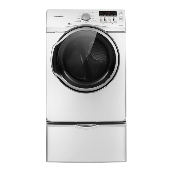
Samsung DV431AEP/XAA Technical Information
Clothes dryer
Hide thumbs
Also See for DV431AEP/XAA:
- User manual (120 pages) ,
- Service manual (50 pages) ,
- Service manual (49 pages)
Advertisement
IMPORTANT SAFETY NOTICE – "For Technicians only" This service data sheet is intended for
use by persons having electrical, electronic, and mechanical experience and knowledge at a level
generally considered acceptable in the appliance repair trade. Any attempt to repair a major
appliance may result in personal injury and property damage. The manufacturer or seller cannot
be responsible, nor assume any liability for injury or damage of any kind arising from the use of
this data sheet.
•
Due to possibility of personal injury or property damage, always contact an authorized
technician for servicing or repair of this unit.
•
Refer to Service Manual (DV431, DV231) for detailed installation, operating, testing,
troubleshooting, and disassembly instructions.
All safety information must be followed as provided in Service Manual of DV431, DV231.
To avoid risk of electrical shock, personal injury or death; disconnect power to dryer
before servicing, unless testing requires power.
CLOTHES DRYER
Technical Information
CAUTION
WARNING
1
Code No. : DC68-02365D-02
Advertisement
Table of Contents

Related Manuals for Samsung DV431AEP/XAA


Summary of Contents for Samsung DV431AEP/XAA
-
Page 1: Technical Information
IMPORTANT SAFETY NOTICE – “For Technicians only” This service data sheet is intended for use by persons having electrical, electronic, and mechanical experience and knowledge at a level generally considered acceptable in the appliance repair trade. Any attempt to repair a major appliance may result in personal injury and property damage. -
Page 2: Error Items And Diagnostic Codes
ALIGNMENT AND ADJUSTMENTS To avoid risk of electrical shock, personal injury or death; disconnect power to dryer before servicing, unless testing requires power. ERROR ITEMS AND DIAGNOSTIC CODES An occurrence of an Error will make a sound of error melody for 5sec and continuously show one of the Error Displays from the following errors. -
Page 3: Test Mode
ALIGNMENT AND ADJUSTMENTS To avoid risk of electrical shock, personal injury or death; disconnect power to dryer before servicing, unless testing requires power. TEST MODE Service Mode (DV431 only) How to enter: To enter Service Mode , press Mixed Load Bell + Temp. Keys 3 seconds in normal mode until it sends out a beeping sound. - Page 4 ALIGNMENT AND ADJUSTMENTS To avoid risk of electrical shock, personal injury or death; disconnect power to dryer before servicing, unless testing requires power. Continuous Run Mode Power On state (Normal user mode) How to enter: Press Mixed Load Bell +Dry Level(DV431) or Wrinkle Prevent + Time(DV231) for 7 sec during Power On State (normal user mode). Once in Continuous Run Mode, display “CC” for 1 sec and the remaining time for 2 sec in turns.
-
Page 5: Trouble Diagnosis
ALIGNMENT AND ADJUSTMENTS To avoid risk of electrical shock, personal injury or death; disconnect power to dryer before servicing, unless testing requires power. TROUBLE DIAGNOSIS As the micom dry machine is configured of the complicate structure, there might be the service call. -
Page 6: Trouble Shooting
TROUBLE SHOOTING To avoid risk of electrical shock, personal injury or death; disconnect power to dryer before servicing, unless testing requires power. No Problem Will Not Start or Run Motor runs/ tumbler will not turn Runs a few minutes and then stops Blows fuses or trips circuit breaker Blows fuses or trips... - Page 7 TROUBLE SHOOTING To avoid risk of electrical shock, personal injury or death; disconnect power to dryer before servicing, unless testing requires power. No Problem The igniter does not glow Igniter glows - No gas ignition The gas is ignited but the flame goes out Improper drying clothes wrinkled...
-
Page 8: Component Testing Procedures
TROUBLE SHOOTING To avoid risk of electrical shock, personal injury or death; disconnect power to dryer before servicing, unless testing requires power. COMPONENT TESTING PROCEDURES Component Electrical Testing (with ohmmeter) Thermistor resistance 10K Ω @ 25°C 77°F Thermostat 1 resistance < 1Ω Thermostat 3 resistance < 1Ω ... -
Page 9: Gas Model
TROUBLE SHOOTING To avoid risk of electrical shock, personal injury or death; disconnect power to dryer before servicing, unless testing requires power. GAS MODEL Radiant Sensor(10RS) Resistance value < 1 Ω If resistance is infinite, replace Radiant sensor Igniter(101D) Resistance value 40~400 Ω If resistance is infinite, replace Igniter WARNING Gas Valve(25M01A) Valve 1-2 : Resistance value 1.2K Ω Valve 1-3 : Resistance value 0.5K Ω... - Page 10 TROUBLE SHOOTING To avoid risk of electrical shock, personal injury or death; disconnect power to dryer before servicing, unless testing requires power. Sensor Bars & temperature sensor check WARNING Sensor Bars - Disconnect harness and test Pink wire Pin 4 to Orange wire Pin 5. Approx ∞ Ω without laundry Approx 190Ω ± 10% with wet clothes Cycling Thermistor - Disconnect harness and test Blue wire Pin 2 to Red wire Pin 6.
- Page 11 TROUBLE SHOOTING To avoid risk of electrical shock, personal injury or death; disconnect power to dryer before servicing, unless testing requires power. 3-WIRE system connections A. External ground connector B. Neutral grounding wire (green/yellow) C. Center silver-colored terminal block screw D.
-
Page 12: Wiring Diagram
WIRING DIAGRAM To avoid risk of electrical shock, personal injury or death; disconnect power to dryer before servicing, unless testing requires power. WIRING DIAGRAM OPTION 1 : Steam Models Only, OPTION 3 : DR READY Models Only WARNING...