Table of Contents
Advertisement
Available languages
Available languages
Quick Links
Download this manual
See also:
Use and Care Manual
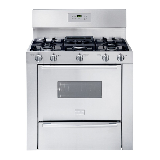
36 " GAS RANGE INSTALLATION INSTRUCTIONS
INSTALLATION AND SERVICE MUST BE PERFORMED BY
IMPORTANT: SAVE FOR LOCAL ELECTRICAL INSPECTOR'S USE.
READ AND SAVE THESE INSTRUCTIONS FOR FUTURE REFERENCE.
If the information in this manual is not followed exactly, a fire
or explosion may result causing property damage, personal injury or death.
FOR YOUR SAFETY:
— Do not store or use gasoline or other flammable vapors and liquids in the
vicinity of this or any other appliance.
— WHAT TO DO IF YOU SMELL GAS:
•
Do not try to light any appliance.
•
Do not touch any electrical switch; do not use any phone in your building.
•
Immediately call your gas supplier from a neighbor's phone. Follow the gas
supplier's instructions.
•
If you cannot reach your gas supplier, call the fire department.
— Installation and service must be performed by a qualified installer, service
agency or the gas supplier.
Dimensions and Clearance
Provide adequate clearance between range
and adjacent combustible surfaces.
3 6 "
(9 1 .4 cm )
4 7 ¾ "
)
(1 2 1 .3 c m
NOTE: Wiring diagram for this appliance is enclosed in this booklet.
Printed in United States
A QUALIFIED INSTALLER.
25 5/8"
(65.1 cm)
3 6 "
c m )
( 9 1 . 4
Minimumclearance on
either side of range
above 36" (91.4 cm)
height if a wall is
installed
36"
(91.4 cm)
36" (91.4 cm)
30"
(76.2 cm)
Minimum
5" (12.7 cm)
(45.7 cm)
M
INUTE
A
DD 1
B
AKE
ROIL
B
L
IGHT
O
VEN
C
LOCK
O
T
VEN
IME
C
OOK
O
N/
O
FF
S
LOW
W
ARM
&
VEN
O
C
OOK
OLD
H
F
LEX
K
ITCHEN
D
ELAY
P
REHEA T
LEAN
C
IMER
T
S
TART
OOR
D
OCKED
L
S
TOP
ECIPE
R
O
O
N/
FF
C
LEAR
R
ECALL
O
L
OCKOUT
VEN
36¼" (92.1 cm)
Between Cabinets
Figure 1
1
Appliances Installed in the
state of Massachusetts:
This Appliance can only be
installed in the state of
Massachusetts by a
Massachusetts licensed
plumber or gasfitter.
This appliance must be
installed with a 3 foot (36 in.)
long flexible gas connector.
A "T" handle type manual gas
valve must be installed in the
gas supply line to this
appliance.
Minimum to
cabinets on
18"
Maximum depth
either side
for cabinets
of range
above range top
0" Min. Clearance
at rear of range
below cooktop
from the back wall.
P/N 318201760 (0711) Rev. C
English – pages 1-7
Español – páginas 8-15
Wiring Diagram - pages 16
13"
(33 cm)
Advertisement
Table of Contents

Related Manuals for Frigidaire PLGF659EC


Summary of Contents for Frigidaire PLGF659EC
- Page 1 36 " GAS RANGE INSTALLATION INSTRUCTIONS INSTALLATION AND SERVICE MUST BE PERFORMED BY IMPORTANT: SAVE FOR LOCAL ELECTRICAL INSPECTOR'S USE. READ AND SAVE THESE INSTRUCTIONS FOR FUTURE REFERENCE. If the information in this manual is not followed exactly, a fire or explosion may result causing property damage, personal injury or death.
-
Page 2: Important Notes To The Installer
Installation 1982 (Manufactured Home Sites, Communities and Set ups), ANSI Z225.1 latest edition, or local codes. • Before installing the range in an area covered with linoleum or any other synthetic floor covering, make sure the floor covering can withstand heat at least 90°F above room temperature without... -
Page 3: Seal The Openings
The gas supply line should be ½" or ¾" I.D. (Interior Diameter) 3. Seal the openings Seal any openings in the wall behind the range and in the floor under the range after gas supply line is installed. 4. Connect the range to the gas supply... -
Page 4: Lp/Propane Gas Conversion
Wait a few minutes for gas to move through the gas line. Check for leaks. After connecting the range to the gas supply, check the system for leaks with a manometer. If a manometer is not available, turn on the gas supply and use a liquid leak detector (or soap and water) at all joints and connections to check for leaks. -
Page 5: Check Operation
Make sure the range is cold. Remove the service drawer (warmer drawer on some models) and open the oven door. Lift the range at the front and slide it out of the cut-out opening without creating undue strain on the flexible gas conduit. - Page 6 Figure 9), reposition air shutter, and tighten lock screw. 9. Make Sure Range Is Level Check if the range is level by placing a level horizontally on an oven rack. Check diagonally from front to back, then level the range by either adjusting the leveling legs or by placing shims under the corners of the range as needed.
- Page 7 Adjustable Wrench 3/16” Dia. Masonry Drill Bit (if installing in concrete) Attach brackets to the floor at the back of the range to hold both rear leg levelers. When fastening to the floor, be sure that screws do not penetrate electrical wiring or plumbing.
- Page 8 INSTRUCCIONES DE INSTALACION PARA LA ESTUFA A GAS DE 36" LA INSTALACION Y EL SERVICIO DEBEN SER EFECTUADOS POR UN INSTALADOR CALIFICADO. IMPORTANTE: GUARDE ESTAS INSTRUCCIONES PARA USO DEL INSPECTOR LOCAL DE ELECTRICIDAD. LEA Y GUARDE ESTAS INSTRUCCIONES PARA REFERENCIA FUTURA. Si todas las instrucciones de éste manual no son observadas a la letra, se puede ocurrir incendios o explosiones que pueden causar daños materiales, lesiones o la muerte.
-
Page 9: Notas Importantes Para El Instalador
INSTRUCCIONES DE INSTALACION PARA LA ESTUFA A GAS DE 36" Notas importantes para el Instalador 1. Lea todas las instrucciones contenidas en este manual antes de instalar la estufa. 2. Saque todo el material usado en el embalaje del compartimiento del horno antes de conectar el suministro eléctrico o de gas a la estufa. - Page 10 INSTRUCCIONES DE INSTALACION PARA LA ESTUFA A GAS DE 36" • En caso de una interruptión del servicio eléctrico, es posible de encender los quemadores de superficie a mano. Para encender un quemador de superficie, acerque un fósforo encendido del cabezal del quemador, y gire delicadamente el botón de control de superficie a LITE (encendido).
-
Page 11: Requisitos Eléctricos
INSTRUCCIONES DE INSTALACION PARA LA ESTUFA A GAS DE 36" La línea del suministro se debe de ser equipada de una válvula de cierre manual aprobada. Esta válvula se debe localizar en el mismo cuarto que la estufa y debe estar en una localización que permita la facilidad de la abertura y del cierre. -
Page 12: Comprobación Del Funcionamiento
INSTRUCCIONES DE INSTALACION PARA LA ESTUFA A GAS DE 36" En lugares en los que aya un enchufe de pared estándar de dos patillas, el cliente tendrá resposabilidad directa y la obligacíon de reemplazarlo por un enchufe de pared de tres patillas debidemente cableado a tierra. Bajo ninguna circunstancia, corte, retire o deribe la tercera patilla (de toma de tierra) del cable del suministro de energía eléctrica. - Page 13 INSTRUCCIONES DE INSTALACION PARA LA ESTUFA A GAS DE 36" 8.4 Ajuste de la Posición LOW (BAJA) Para la Válvula del Quemador Superior (Figura 7) a. Gire el bottón de control a la posición LITE (encender) hasta que el quemador encienda. b.
- Page 14 INSTRUCCIONES DE INSTALACION PARA LA ESTUFA A GAS DE 36" Tornillos de seguridad Obturador de aire Figura 9 8.5.3 Obturador de aire - Quemador de asado La longitud aproximada de la llama del quemador de asado es 1 pulgada (interior claro, llama azul). Para determinar si la llama del quemador de asado es la adecuada, poner el horno en la opción asar.
- Page 15 INSTRUCCIONES DE INSTALACION PARA LA ESTUFA A GAS DE 36" 10. Instrucciones para de instalación del soporte antivuelco Advertencia de seguridad importante Esta estufa debe ser asegurada al piso usando las platinas de anclaje y los tornillos suministrados. El no instalar apropiadamente los soportes llegar a permitir que la estufa se incline hacia adelante, accidentalmente, si se coloca un peso excesivo sobre la...
- Page 16 WIRING DIAGRAM - DIAGRAMA DE LA INSTALACIÓN ALÁMBRICA ELECTRONIC OVEN CONTROL CONTROL DE HORNO ELECTRONICO ES 345 BR-22 V-22 V-22 TEMPERATURE PROBE SONDA DE TEMPERATURA O-22 SW.A MDL SW. BL-22 BK-22 BK-22 BK-22 BK-22 BK-22 DOOR SWITCH INTERROPTOR DE LUZ DE PUERTA COOKTOP CIRCUIT // CIRCUITO DE PLANCHIA DE COCINAR NOTE: SERVICE:IF REPLACEMENT OF TERMINALS BECOMES NECESSARY,COMPARABLE WIRE TYPE AND...