Sony STR-DA3500ES Operating Instructions Manual
Hi-fi receivers: premium 7.1 multi-room av receiver
Hide thumbs
Also See for STR-DA3500ES:
- Operating instructions manual (136 pages) ,
- Quick setup manual (2 pages) ,
- Specifications (2 pages)

Related Manuals for Sony STR-DA3500ES


Summary of Contents for Sony STR-DA3500ES
- Page 1 4-144-907-11(1) Multi Channel AV Receiver Operating Instructions STR-DA3500ES ©2009 Sony Corporation...
-
Page 2: Important Safety Instructions
The model and serial numbers are located on the rear of the unit. Record these numbers in the space provided below. Refer to them whenever you call upon your Sony dealer regarding this product. Model No. Important Safety Instructions 1) Read these instructions. - Page 3 12)Use only with the cart, stand, tripod, bracket, or table specified by the manufacturer, or sold with the apparatus. When a cart is used, use caution when moving the cart/apparatus combination to avoid injury from tip-over. 13)Unplug this apparatus during lightning storms or when unused for long periods of time.
-
Page 4: About This Manual
Neural-THX Surround. This product using Neural-THX manufactured under license from Neural Audio Corporation and THX Ltd. Sony Corporation hereby grants the user a non-exclusive, non-transferable, limited right of use to this product under USA and foreign patent, patent pending and other technology or trademarks owned by Neural Audio Corporation and THX Ltd. -
Page 5: Table Of Contents
Table of Contents Getting Started Description and location of parts ... 7 1: Installing the speakers ... 15 2: Connecting the speakers ... 17 3: Connecting the TV ... 19 4a: Connecting the audio components ... 20 4b: Connecting the video components ... 25 5: Connecting the antennas (aerials) ... - Page 6 Other Operations Converting analog video input signals ...96 Enjoying the sound/images from the components connected to the DIGITAL MEDIA PORT ...97 Naming inputs ...101 Switching between digital and analog audio (INPUT MODE) ...101 Enjoying the sound/images from other inputs ...102 Changing the display window ...105 Using the sleep timer ...108 Recording using the receiver ...109...
-
Page 7: Getting Started
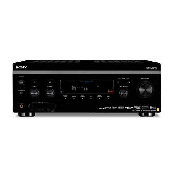
Getting Started Description and location of parts Front panel Status of the POWER button The receiver is turned off (the ON/ STANDBY lamp lights off) (initial setting). Press POWER to turn the receiver on. You cannot turn the receiver on using the remote. - Page 8 Name Function A POWER Press to turn the receiver on or off. ON/STANDBY Shows the status of the lamp receiver. B TONE MODE Adjust the bass and treble for the front, TONE +/– center and surround/ surround back channels. Press TONE MODE repeatedly to select the item you want, then turn TONE...
-
Page 9: Rear Panel
Rear panel A DIGITAL INPUT/OUTPUT section OPTICAL IN/ Connect to a DVD OUT jacks player, Super Audio CD player, etc. The COAXIAL jack COAXIAL IN provides a better jacks sound quality (page 19, 21, 29, 30). HDMI IN/ Connect to a DVD OUT* jacks player, Blu-ray disc player, or a satellite... -
Page 10: Component Video Input
D Control jacks for Sony equipment and other external components IR REMOTE Connect to an IR IN/OUT jacks repeater (page 91). TRIGGER Connects to an OUT jack interlock on/off of the power supply of other 12V TRIGGER compliant components, or the... - Page 11 Remote commander You can use the supplied remote commander to operate the receiver and to control the Sony audio/video components that the remote is assigned to operate (page 124). Multi function remote commander (RM-AAL026) Name Function A AV ?/1 (on/...
- Page 12 DVD player, Blu- ray disc player, etc. Press TV (Z), then press TOOLS/OPTIONS to display the options of the Sony TV. L MENU Press AMP (4), then press MENU to display the menu to operate the receiver.
- Page 13 Name Function N PRESET Press to register FM/AM/ /– satellite tuner stations or to select preset stations. TV CH + /– Press TV (Z), then press TV CH +/– to operate the TV, satellite tuner, VCR, etc. O F1/F2 Press to select a component to operate.
- Page 14 Simple remote commander (RM-AAU039) This remote can only be used to operate the receiver. You can control the main functions of the receiver with simple operations using this remote. SLEEP DISPLAY GUI MODE Name Function A ?/1 (on/ Press to turn a receiver on or off. standby) B A.F.D.
-
Page 15: 1: Installing The Speakers
1: Installing the speakers This receiver allows you to use a 7.1 channel system (7 speakers and one subwoofer). Enjoying a 5.1/7.1 channel system To fully enjoy theater-like multi channel surround sound requires five speakers (two front speakers, a center speaker, and two surround speakers) and a subwoofer (5.1 channel system). - Page 16 Tips • The angle A should be the same. • When you connect a 6.1 channel speaker system, place the surround back speaker behind the seating position. • Since the subwoofer does not emit highly directional signals, you can place it wherever you want.
-
Page 17: 2: Connecting The Speakers
2: Connecting the speakers Before connecting cords, make sure to disconnect the AC power cord (mains lead). (10 mm) A Monaural audio cord (not supplied) B Speaker cords (not supplied) AFront speaker A (Left) BFront speaker A (Right) CCenter speaker DSurround speaker (Left) ESurround speaker (Right) FSurround back speaker (Left) - Page 18 If you connect only one surround back speaker, connect it to the SPEAKERS SURROUND BACK L terminals. When you connect a subwoofer with an auto standby function, turn off the function when watching movies. If the auto standby function is set to on, it turns to standby mode automatically based on the level of the input signal to a subwoofer, then sound may not be output.
-
Page 19: 3: Connecting The Tv
A Optical digital cord (not supplied) B Audio cord (not supplied) C HDMI cable (not supplied) Sony recommends that you use an HDMI-authorized cable or Sony HDMI cable. D Component video cord (not supplied) E Video cord (not supplied) It is not necessary to connect all the cords. -
Page 20: 4A: Connecting The Audio Components
Notes • Be sure to turn on the receiver when the video and audio signals of a playback component are being output to a TV via the receiver. Unless the power is turned on, neither video nor audio signals will be transmitted. -
Page 21: Connecting Components With Digital Audio Input/Output Jacks
Connecting components with digital audio input/output jacks The following illustration shows how to connect a Super Audio CD player, CD player, an MD deck and DIGITAL MEDIA PORT adapter. DIGITAL MEDIA PORT MD deck adapter A Optical digital cord (not supplied) B Audio cord (not supplied) C Coaxial digital cord (not supplied) Super Audio CD... - Page 22 Notes on connecting a DIGITAL MEDIA PORT adapter • When connecting the DIGITAL MEDIA PORT adapter, be sure the connector is inserted with the arrow mark facing towards the arrow mark on the DMPORT jack. • Be sure to make DMPORT connections firmly, insert the connector straight in.
-
Page 23: Connecting Components With Multi Channel Output Jacks
Connecting components with multi channel output jacks If your DVD player, Blu-ray disc player or Super Audio CD player is equipped with multi channel output jacks, you can connect them to the MULTI CHANNEL INPUT jacks of this receiver to enjoy multi channel sound. Alternatively, the multi channel input jacks can be used to connect an external multi channel decoder. -
Page 24: Connecting Components With Analog Audio Jacks
Connecting components with analog audio jacks The following illustration shows how to connect a component with analog jacks, such as a tape deck, turntable, etc. Turntable A Audio cord (not supplied) Note If your turntable has a ground (earth) wire, connect it to the (U) SIGNAL GND terminal. -
Page 25: 4B: Connecting The Video Components
4b: Connecting the video components How to hook up your components This section describes how to hook up your components to this receiver. Before you begin, see “Component to be connected” below for the pages which describe how to connect each component. - Page 26 Connecting components with HDMI jacks HDMI is the abbreviated name for High- Definition Multimedia Interface. It is an interface which transmits video and audio signals in digital format. HDMI features • A digital audio signals transmitted by HDMI can be output from the speakers and the PRE OUT jacks on this receiver.
-
Page 27: Dvd Player
Satellite tuner, set-top box Audio/video signals A HDMI cable (not supplied) Blu-ray disc player, PS3™, hard disk recorder Audio/video signals Audio/video signals TV, projector, etc. DVD player Audio/video signals continued... -
Page 28: Notes On Connecting Cables
Standard HDMI cable, 1080p or Deep Color (Deep Colour) images may not be displayed properly. • Sony recommends that you use an HDMI- authorized cable or Sony HDMI cable. • We do not recommend using an HDMI-DVI conversion cable. When you connect an... -
Page 29: Connecting A Dvd Player
Connecting a DVD player The following illustration shows how to connect a DVD player. It is not necessary to connect all the cords. Connect the audio and video cords according to the jacks of your components. Audio signals A Optical digital cord (not supplied) B Coaxial digital cord (not supplied) C Audio cord (not supplied) D Component video cord (not supplied) -
Page 30: Blu-Ray Disc Player
Connecting a Blu-ray disc player The following illustration shows how to connect a Blu-ray disc player. It is not necessary to connect all the cords. Connect the audio and video cords according to the jacks of your components. Audio signals A Optical digital cord (not supplied) B Coaxial digital cord (not supplied) C Audio cord (not supplied) -
Page 31: Satellite Tuner, Set-Top Box
Connecting a satellite tuner, set-top box The following illustration shows how to connect a satellite tuner or set-top box. It is not necessary to connect all the cords. Connect the audio and video cords according to the jacks of your components. Audio signals A Audio cord (not supplied) B Component video cord (not supplied) -
Page 32: Dvd Recorder, Vcr
Connecting components with analog video and audio jack The following illustration shows how to connect a component which has analog jacks such as a DVD recorder, VCR, etc. Audio signals A Audio cord (not supplied) B Video cord (not supplied) C Audio/video cord (not supplied) It is not necessary to connect all the cords. - Page 33 Function for conversion of video signals This receiver is equipped with a function for converting video signals. You can output the video signal after connecting this receiver via the MONITOR OUT or HDMI OUT jack as shown in the illustration. In the video input/output conversion table of the receiver Output Signals OUTPUT jack...
- Page 34 Notes on converting video signals • When video signals from a VCR, etc., are converted on this receiver and then output to your TV, depending on the status of the video signal output, the image on the TV screen may appear distorted horizontally or no image may be output.
- Page 35 In the video input/output conversion table classified by the menu settings For details on “Resolution” menu setting, see “Settings for the video (Video settings menu)” (page 57) and on operating, see “Converting analog video input signals” (page 96). Output from “Resolution”...
-
Page 36: 5: Connecting The Antennas (Aerials)
5: Connecting the antennas (aerials) Connect the supplied AM loop antenna (aerial) and FM wire antenna (aerial). Before connecting the antennas (aerials), be sure to disconnect the AC power cord (mains lead). FM wire antenna (aerial) (supplied) Notes • To prevent noise pickup, keep the AM loop antenna (aerial) away from the receiver and other components. -
Page 37: 6: Preparing The Receiver And The Remote
6: Preparing the receiver and the remote Connecting the AC power cord (mains lead) Connect the supplied AC power cord (mains lead) to the AC INLET terminal on the receiver, then connect the AC power cord (mains lead) to a wall outlet (mains). Notes •... -
Page 38: The Receiver
You can switch the command mode (AV SYSTEM 1 or AV SYSTEM 2) of the receiver and the remote. If both the receiver and the other Sony component respond to the same remote command, switch the command mode of either the component or the receiver to... - Page 39 To switch the command mode of the multi function remote commander RM SET 1, 2 While holding down RM SET UP, press ?/1. The AMP and ZONE buttons flash. Press AMP. The ZONE button lights off, the AMP button keeps flashing and the SHIFT button lights up.
-
Page 40: 7: Operating The Receiver Using The Gui (Graphical User Interface)
7: Operating the receiver using the GUI (Graphical User Interface) You can change the display mode of the menu to screen mode using the following procedures. By using the GUI menu, you can make various settings and adjustments. See “Operating without connecting to the TV” (page 111) if you are not going to use a GUI menu. - Page 41 FM/AM/XM/SIRIUS You can listen to the radio using the receiver. For details on the Tuner operation, see “Tuner Operations” (page 71). Settings You can use the Settings menu to set and adjust this receiver. Auto Calibration You can use the Auto Calibration settings menu to adjust the speakers automatically.
- Page 42 Press V/v repeatedly to select a menu you want. Press or b to enter the menu. The menu item list appears on the TV screen. Press V/v repeatedly to select the menu item you want to adjust. Press or b to enter the menu item.
-
Page 43: 8: Setting The Speakers
8: Setting the speakers Setting the speaker impedances Set the appropriate speaker impedance for the speakers you are using. Press GUI MODE repeatedly to select “GUI ON”. The GUI menu appears on the TV screen. Press MENU if the GUI menu does not appear on the TV screen. -
Page 44: 9: Calibrating The Appropriate Speaker Settings Automatically (Auto Calibration)
Selecting the front speakers You can select the front speakers you want to drive. SPEAKERS (OFF/A/B/A+B) Press SPEAKERS (OFF/A/B/A+B) repeatedly to select the front speaker system you want to drive. Note This setting is not available when headphones are connected. To select The speakers connected to the FRONT SPEAKERS A terminals. - Page 45 Before you perform the Auto Calibration Before you perform the Auto Calibration, set up and connect the speakers (page 15-18). • The AUTO CAL MIC jack is used for the supplied optimizer microphone only. Do not connect other microphones. Doing so may damage the receiver and the microphone.
-
Page 46: Performing Auto Calibration
On setting up the active subwoofer • When a subwoofer is connected, turn on the subwoofer and turn up the volume beforehand. Turn the MASTER VOLUME knob to just before the mid-point. • If you connect a subwoofer with the crossover frequency function, set the value to maximum. - Page 47 The measurement starts in five seconds. Measurement starts. The measurement process will take approximately 30 seconds with a test tone. Wait until the measurement process completes. Tips • Operations other than turning the receiver on or off are deactivated during the measurement. •...
- Page 48 Makes the measurement of frequency from each speaker flat. Engineer Sets the frequency to one that matches that of the Sony listening room standard. Front Reference Adjusts the characteristics of all the speakers to match the characteristics of the front speaker.
- Page 49 Message list after Auto Calibration measurement Message Explanation appears in GUI menu [Display window] Error Code: 31 SPEAKERS (OFF/A/B/A+B) is set to off. Set it to others and perform the measurement [E-xxx: 31]* again. Error Code: 32 None of the speakers were detected. Make sure that the optimizer microphone is connected [E-xxx: 32]* properly and perform the measurement again.
-
Page 50: Playback
When a warning code appears If a warning on the measurement result is present, detailed information is displayed. Press to return to step 1 of “Confirming/saving the measurement results” (page 47). Depending on the position of the subwoofer, the measurement results for polarity may vary. However, there will be no problems even if you continue to use the receiver with that value. -
Page 51: Start Playback
You can also use INPUT SELECTOR on the receiver. Selected Components that can be input played back VIDEO1 VCR, etc., connected to the VIDEO 1 jack. VIDEO2 Camcorder and video game, etc., connected to the VIDEO 2 IN jack. Blu-ray disc player, etc., connected to the BD jack. -
Page 52: Listening To A Super Audio Cd/Cd
Listening to a Super Audio CD/CD SLEEP DISPLAY GUI MODE • The operation is described for a Sony Super Audio CD player. • Refer to the operating instructions supplied with the Super Audio CD player or CD player. You can select the sound field to suit the music. -
Page 53: Watching A Dvd/Blu-Ray Disc
Watching a DVD/Blu-ray Disc SLEEP DISPLAY GUI MODE • Refer to the operating instructions supplied with the TV and DVD player or Blu-ray disc player. • Check the following if you cannot listen to the multi channel sound. – Be sure the sound source corresponds to the multi channel format (the MULTI CHANNEL DECODING... -
Page 54: Enjoying Video Games
Enjoying video games SLEEP DISPLAY GUI MODE Refer to the operating instructions supplied with the TV and video game. VIDEO 2 IN Turn on the TV and video game. Turn on the receiver. Press INPUT SELECTOR U/u to select “VIDEO 2”*. You can also use INPUT SELECTOR on this receiver to select “VIDEO 2”*. -
Page 55: Watching Video
Watching video SLEEP DISPLAY GUI MODE Refer to the operating instructions supplied with the TV and VCR. Turn on the VCR. Turn on the receiver. Press INPUT SELECTOR U/u to select “VIDEO 1”*. You can also use INPUT SELECTOR on this receiver to select “VIDEO 1”*. -
Page 56: Amplifier Operations
Amplifier Operations Settings for the audio (Audio settings menu) You can use the Audio settings menu to make settings for the audio to suit your preference. Select “Audio” in the Settings menu. For details on adjusting the parameters, see “7: Operating the receiver using the GUI (Graphical User Interface)”... -
Page 57: Settings For The Video (Video Settings Menu)
Settings for the video (Video settings menu) You can use the Video settings menu to make settings for video. Select “Video” in the Settings menu. For details on adjusting the parameters, see “7: Operating the receiver using the GUI (Graphical User Interface)” (page 40). -
Page 58: Settings For The System (System Settings Menu)
• AMP The HDMI audio signals from the playback component is only output to speakers connected to the receiver. The multi channel sound can be played back as it is. Note Audio signals are not output from the TV’s speakers when “Audio Out” is set to “AMP”. x 24p Auto Sound Sync (24p Auto Sound Sync) Lets you turn the “24p Auto Sound Sync”... -
Page 59: Enjoying Surround Sound
Enjoying Surround Sound Enjoying a pre- programmed sound field Start playing a sound source you want to listen to (CD, DVD, etc.). Press GUI MODE repeatedly to select “GUI ON”. The GUI menu appears on the TV screen. Press MENU if the GUI menu does not appear on the TV screen. - Page 60 To select the Effect Type for HD- D.C.S. Press V/v repeatedly to select “Sound Field Setup”, then press Press V/v repeatedly to select “HD- D.C.S.”, then press b. Press V/v to select the Effect Type you want, then press B. HD-D.C.S.
- Page 61 When connecting Blu-ray disc players and other next generation HD players This receiver supports the following audio formats. Audio format Dolby Digital Dolby Digital EX Dolby Digital Plus Dolby TrueHD DTS-ES DTS 96/24 DTS-HD High Resolution Audio a) b) DTS-HD Master Audio Multi channel Linear PCM Audio signals are output in another format if the playback component does not correspond to the format.
- Page 62 Types of A.F.D. mode The Auto Format Direct (A.F.D.) mode allows you to listen to higher fidelity sound and select the decoding mode for listening to a 2 channel stereo sound as multi channel sound. A.F.D. mode A.F.D. Auto Enhanced Surround Pro Logic II* Pro Logic IIx* Neo:6 Cinema...
- Page 63 Types of music/movie mode You can take advantage of surround sound simply by selecting one of the receiver’s preprogrammed sound fields. They bring the exciting and powerful sound of movie theaters and concert halls into your home. Sound field Sound field Movie HD-D.C.S.
-
Page 64: Resetting Sound Fields To The Initial Settings
Tips • For details on HD-D.C.S. technology, see “Glossary” (page 132). • When a sound field with HD-D.C.S. is selected, the HD-D.C.S. lamp lights up on the display window. To turn off the surround effect for MOVIE/MUSIC Select “2ch Stereo” or “A.F.D. Auto” in the Surround settings menu. -
Page 65: Enjoying The Surround Effect At Low Volume Levels (Night Mode)
Enjoying the surround effect at low volume levels (NIGHT MODE) This function allows you to retain a theater like environment at low volume levels. This function can be used with other sound fields. When watching a movie late at night, you will be able to hear the dialog clearly even at a low volume level. - Page 66 Press V/v repeatedly to select “Manual Setup”, then press Press V/v/B/b repeatedly to select speaker you want to adjust. Press Press B/b repeatedly to select the parameter you want. Press V/v repeatedly to adjust the setting. Manual Setup menu parameters x Level (Level of speaker) You can adjust each speaker’s level (center,...
- Page 67 Note When one of the sound fields for music is selected, no sound is output from the subwoofer if all the speakers are set to “LARGE”. However, the sound will be output from the subwoofer if the digital input signal contains LFE signals, or if the front or surround speakers are set to “SMALL”, the sound field for movie is selected, or “Portable Audio”...
- Page 68 Press V/v repeatedly to select the speaker pattern you want. Making settings with the Test Tone menu Press GUI MODE repeatedly to select “GUI ON”. The GUI menu appears on the TV screen. Press MENU if the GUI menu does not appear on the TV screen.
-
Page 69: Speaker Settings
Test Tone menu parameters x Test Tone (Test Tone) • OFF • AUTO The test tone is output from each speaker in sequence. • L, C, R, SR, SB, SBR, SBL, SL, SW You can select which speakers will output the test tone. -
Page 70: Adjusting The Equalizer
x D. Range Comp (Dynamic range compressor) Lets you compress the dynamic range of the sound track. This may be useful when you want to watch movies at low volumes late at night. Dynamic range compression is possible with Dolby Digital sources only. •... -
Page 71: Tuner Operations
Press V/v repeatedly to select “EQ”, then press Press B/b repeatedly to select the speaker you want to adjust, then press Press B/b repeatedly to select “Bass” or “Treble”, then press V/v to adjust the parameter. You can adjust the front speaker bass and treble level with TONE MODE and TONE +/–... -
Page 72: Direct Tuning
Press V/v to select “Auto Tuning”, then press Press V/v. Press V to scan from low to high, press v to scan from high to low. The receiver stops scanning whenever a station is received. In case of poor FM stereo reception Press OPTIONS. -
Page 73: Presetting Radio Stations
Press SHIFT, then press the numeric buttons to enter the frequency, then press Example 1: FM 102.50 MHz Select 1 b 0 b 2 b 5 Example 2: AM 1,350 kHz Select 1 b 3 b 5 b 0 If you have tuned in an AM station, adjust the direction of the AM loop antenna (aerial) for optimum reception. -
Page 74: Listening To Satellite Radio
Repeat steps 3 to 7 to preset another station. To tune to preset stations Repeat steps 1 and 2 of “Presetting radio stations”. Press V/v to select the preset station you want. You can select a preset station as follows: •... - Page 75 To subscribe to SIRIUS, U.S. and Canadian customers can call 1-888-539-SIRI (1-888- 539-7474) or visit sirius.com (US) or siriuscanada.ca (Canada). SIRIUS, XM and all related marks and logos are trademarks of Sirius XM Radio Inc. and its subsidiaries. All other marks and logos are the property of their respective owners.
- Page 76 Aiming the XM Radio or SIRIUS antenna MENU Press GUI MODE repeatedly to select “GUI ON”. The GUI menu appears on the TV screen. Press MENU if the GUI menu does not appear on the TV screen. Press V/v repeatedly to select “XM”...
- Page 77 Press V/v repeatedly to select “XM” or “SIRIUS”, then press or b. SIRIUS Press OPTIONS, then press V/v repeatedly to select “Radio ID” or “Sirius ID”, then press SIRIUS Check the XM Radio ID or Sirius ID on the TV screen and write it in the space provided here.
-
Page 78: Channel Number
Press V/v repeatedly to select the category, then press • ALL: You can select a channel from all the categories. • (category name): You can select a channel from one category. SIRIUS When the “Preset Mode” screen is displayed, press OPTIONS, then press V/v repeatedly to select “Category Mode”. - Page 79 Presetting the channels You can select the channels you want directly by presetting them using the preset numbers. You can preset up to 30 XM Radio channels and 30 SIRIUS Satellite Radio channels. MENU Press GUI MODE repeatedly to select “GUI ON”. The GUI menu appears on the TV screen.
- Page 80 Restricting access to specific channels (Parental Lock) (SIRIUS only) You can restrict access to certain channels using your own lock code. The lock code is set to “0000” as the default. Change the lock code before you use this function for the first time (see “To change the lock code”...
-
Page 81: To Listen To The Locked Channels
Press SHIFT, then press the numeric buttons to enter your 4-digit lock code. “The channel has been locked.” appears and the Parental Lock is set. To delete the numbers you have entered, go back to step 4 by pressing RETURN/ EXIT O, and then repeat the procedure above from step 4. - Page 82 XM Radio message list Message Explanation appears in GUI menu [Display window] Check Antenna The XM antenna is not connected to [ANTENNA] the XM Mini-Tuner and Home Dock or the XM antenna cable is damaged. CH Unauthorized You have selected an XM channel that [UNAUTH] is blocked or cannot be received with your XM subscription package.
- Page 83 SIRIUS Satellite Radio message list Message Explanation appears in GUI menu [Display window] Antenna Error The antenna is not connected properly. Check the connection between the SiriusConnect [ANTENNA] Acquiring Signal The receiving condition is not good. [ACQUIRING] CALL 888, 539- You have not subscribed for the SIRI selected channel.
-
Page 84: Bravia" Sync Features
“BRAVIA” Sync features Using “BRAVIA” Sync features What is “BRAVIA” Sync? “BRAVIA” Sync is compatible with a Sony TV, Blu-ray Disc/DVD player, AV amplifier, etc., that is equipped with the Control for HDMI function. By connecting Sony components that are compatible with the “BRAVIA”... - Page 85 Audio/video signals A HDMI cable (not supplied) Sony recommends that you use an HDMI-authorized cable or Sony HDMI cable. B Optical digital cord (not supplied) C Audio cord (not supplied) Connect at least one of the audio cords (B or C).
-
Page 86: Preparing Control For Hdmi Function
Preparing Control for HDMI function This receiver supports the Control for HDMI- Easy Setting function. This function is only available for certain types of TV. When you perform the Control for HDMI-Easy Setting on the TV, the Control for HDMI setting on this receiver will automatically change accordingly. -
Page 87: Playing Back Components With One-Touch Operation (One-Touch Play)
To set Control for HDMI Press GUI MODE repeatedly to select “GUI ON”. The GUI menu appears on the TV screen. Press MENU if the GUI menu does not appear on the TV screen. Press V/v repeatedly to select “Settings” then press The settings menu list appears on the TV screen. -
Page 88: Enjoying The Tv Sound From The Speakers Connected To The Receiver (System Audio Control)
Enjoying the TV sound from the speakers connected to the receiver (System Audio Control) You can enjoy the TV sound from the speakers connected to the receiver by a simple operation. Depending on the TV settings, while you are watching the TV, the receiver turns on and switches to the “TV”... -
Page 89: Enjoying Movies With The Optimum Sound Field (Theater Mode Sync)
Enjoying movies with the optimum sound field (Theater Mode Sync) Press the THEATER button on the remote of the receiver, TV, or the Blu-ray Disc Player, while pointing the remote toward the TV. The sound field switches to HD-D.C.S. To return to the previous sound field, press the THEATER button again. -
Page 90: Using Multi-Zone Features
When using an IR repeater (not supplied), you can operate both a component in the main zone and Sony receiver in zone 2 or zone 3 from zone 2 or zone 3. Use the multi function remote in zone 2 or zone 3. -
Page 91: Making A Multi-Zone Operation
ZONE 2 AUDIO A Audio component B Video component C IR repeater (not supplied) D Speakers E Sony Amplifier/Receiver * You can also connect to the COMPONENT VIDEO OUT (ZONE 2) jack. IR REMOTE IN STR-DA3500ES IR REMOTE IN STR-DA3500ES... - Page 92 2: Zone 3 connections Main zone Zone 3 IR REMOTE IN STR-DA3500ES ZONE 3 AUDIO OUT Multi function remote A IR repeater (not supplied) B Speakers C Sony Amplifier/Receiver...
- Page 93 Setting the speakers in zone 2 When the speakers in zone 2 are connected to the SPEAKERS SURROUND BACK terminals of the receiver (page 91), make the setting so that the sound selected in zone 2 is output from the speakers connected to the SPEAKERS SURROUND BACK terminals.
- Page 94 Press V/v to select “Zone2-ON”/“Zone3-ON” or “Zone2-OFF”/“Zone3-OFF”, then press Press V/v/B/b repeatedly to select item and parameter, then press Note You can only enjoy the sound in zone 3. Multi Zone menu parameters x Power Lets you turn zone operation on. •...
-
Page 95: Switching The Zone Setting Of The Remote
Switching the zone setting of the remote The remote commander is initially set to be used in zone 2. If you want to use it in zone 3, switch the zone setting of the remote. RM SET SHIFT Press ?/1 while pressing RM SET UP. -
Page 96: Other Operations
Press ZONE. The remote switches to zone 2 or zone 3 mode. Change the zone setting of the remote to zone 2 or zone 3 in advance (page 95). Turn on the amplifier in zone 2 or zone 3. Press one of the input buttons on the remote to select the source signals you want to output. -
Page 97: Enjoying The Sound/Images From The Components Connected To The Digital Media Port
MEDIA PORT adapter. For details on connecting the DIGITAL MEDIA PORT adapter, see “Connecting components with digital audio input/output jacks” (page 21). Sony offers the following DIGITAL MEDIA PORT adapters: • TDM-BT1/BT10 Bluetooth™ Wireless Audio Adapter • TDM-NW10 DIGITAL MEDIA PORT Adapter •... - Page 98 Press OPTIONS to display “Function List”. Press V/v to select “DMPORT Control”, then press You can select the following modes in this menu: • System GUI This mode is for the TDM-iP50 and TDM-NC1. The list of tracks will be displayed on the GUI screen of the receiver.
- Page 99 To operate the TDM-iP50 using the iPod menu Make sure that “iPod” is selected in step 5 in “Selecting an operation screen to operate the component connected to the DIGITAL MEDIA PORT adapter” (page 97). For details on operating the iPod, refer to the operating instruction supplied with the iPod.
- Page 100 TDM-iP50 x Shuffle ( Plays all the tracks in random order. • Off Deactivates the shuffle play mode. • Albums Plays all the tracks on an album in random order. • Songs Plays all the tracks in “Songs” in random order.
-
Page 101: Naming Inputs
Naming inputs You can enter a name of up to 8 characters for inputs and display it. This is convenient for labeling the jacks with the names of the connected components. Choose the item you want to name. You can name the following items. •... -
Page 102: Enjoying The Sound/Images From Other Inputs
Audio input modes • AUTO Gives priority to digital audio signals when there are both digital and analog connections. If there are more than one digital connection, HDMI audio signals have priority over COAXIAL and OPTICAL audio signals. If there are no digital audio signals, analog audio signals are selected. - Page 103 Press V/v repeatedly to select “Input”, then press Press V/v to select the input name you want to assign. Press OPTIONS, then select “Input Assign” and then press Select the audio and/or video signals you want to assign to the input which you selected in step 3 using V/v/B/b, then press Press RETURN/EXIT O to...
- Page 104 Input name Assignable Video1: video input jacks Composite Video2: Composite BD: Composite DVD: Composite SAT: Composite HDMI1 HDMI2 HDMI3 HDMI4 Component1 Component2 Component3 None Assignable Video1: OPT audio input jacks Video2: OPT MD/TAPE: OPT BD: COAX DVD: COAX SA-CD/CD: COAX Analog Notes •...
-
Page 105: Changing The Display Window
Changing the display window You can check the sound field, etc., by changing the information on the display window. DISPLAY Press DISPLAY repeatedly. Each time you press DISPLAY, the display will change as follows. Input name you selected* t Original input name t Sound field type t Volume level If you see “GUI MODE”... - Page 106 About the indicators on the display window COAX OPT MULTI IN DTS - HD MSTR HI RES HDMI DMPORT ANALOG LPCM S SR SB L SB SB R Name Function A SW Lights up when subwoofer is connected and the audio signal is output from the SUBWOOFER jack.
- Page 107 Name Function J D.RANGE Lights up when dynamic range compression is activated. K CAT Lights up when category mode is selected during the satellite radio operation. L Tuner Lights up when using the indicators receiver to tune in radio stations, etc. M SP A/SP B/ Lights up according to the SP A+B...
-
Page 108: Using The Sleep Timer
Name Function wk Playback The letters (L, C, R, etc.) channel indicate the channels being indicators played back. The boxes around the letters vary to show how the receiver downmixes the source sound (based on the speaker settings). Front Left Front Right Center (monaural) Surround Left... -
Page 109: Recording Using The Receiver
Recording using the receiver You can record from a video/audio component using the receiver. Refer to the operating instructions supplied with your recording component. Recording onto a MiniDisc or audio tape You can record onto a MiniDisc or audio tape using the receiver. -
Page 110: Using A Bi-Amplifier Connection
Recording onto a recording media Press the input button of the playback component. You can also use INPUT SELECTOR on the receiver. Prepare the component for playing. For example, insert the video tape you want to copy into the VCR. Prepare the recording component. -
Page 111: Operating Without Connecting To The Tv
To set up the speakers Set “Sur Back Assign” to “BI-AMP” in the Speaker settings menu. The same signals output from the SPEAKERS FRONT A terminals can be output from the SPEAKERS SURROUND BACK terminals by setting “Sur Back Assign” to “BI-AMP”. Notes •... - Page 112 Press or b to enter the menu. Press V/v repeatedly to select the parameter you want to adjust. or b to enter the Press parameter. Press V/v repeatedly to select the setting you want. Press to enter the setting. To return to the previous display Press To exit the menu...
-
Page 113: Overview Of The Menus
Overview of the menus The following options are available in each menu. For details on navigating through menus, see page 41. Menu Parameters [Display [Display window] window] Auto Calibration Auto Calibration start [<AUTO CAL>] [A.CAL START] Calibration type [CAL TYPE] Position [POSITION] Naming Inputs... - Page 114 Menu Parameters [Display [Display window] window] Speaker Settings Speaker pattern [<SPEAKER>] [SP PATTERN] Front speakers [FRT SIZE] Center speaker [CNT SIZE] Surround speakers [SUR SIZE] Surround Back Speaker Assign [SB ASSIGN] Front left speaker distance [FL DIST.] Front right speaker distance [FR DIST.] Center speaker distance [CNT DIST.]...
- Page 115 Menu Parameters [Display [Display window] window] Surround Sound field selection Settings [S.F. SELECT] [<SURROUND>] Enhanced Surround mode [E.SUR MODE] Effect Type [EFFECT] EQ Settings Front speakers bass level [<EQ>] [FRT BASS] Front speakers treble level [FRT TREBLE] Center speaker bass level [CNT BASS] Center speaker treble level [CNT TREBLE]...
- Page 116 Menu Parameters [Display [Display window] window] Audio Settings Synchronizes audio with video [<AUDIO>] output [A/V SYNC] Digital broadcast language selection [DUAL MONO] Digital audio input decoding priority [DEC. PRIO] Audio input assignment [A. ASSIGN] Video Settings Video signals conversion [<VIDEO>] [RESOLUTION] Video input assignment [V.
- Page 117 Performing Auto Calibration For details on the Auto Calibration, see “9: Calibrating the appropriate speaker settings automatically (Auto Calibration)” (page 44). See “Before you perform the Auto Calibration” (page 45) before performing the Auto Calibration. To operate on the receiver Press GUI MODE repeatedly to select “GUI OFF”.
- Page 118 Makes the measurement of frequency from each speaker flat. ENGINEER Sets the frequency characteristics to a set that matches that of the Sony listening room standard. FRONT REF Adjusts the characteristics of all the speakers to match the characteristics of the front speaker.
-
Page 119: Tuning Radio Stations
Selecting a sound field type For details on each sound field type, see “Enjoying a pre-programmed sound field” (page 59). Press 2CH/A.DIRECT, A.F.D., MOVIE (or MOVIE (HD-D.C.S.) on the receiver), or MUSIC repeatedly. The selected sound field type appears on the display window. -
Page 120: Selecting A Preset Station
Presetting radio stations Tune in the station that you want to preset. For details on the operation, see “Tuning radio stations” (page 119). Press SHIFT and then press ENT/MEM. “MEM” lights up on the display window for a few seconds. Perform steps 3 and 4 before “MEM”... - Page 121 SIRIUS Signal Strength Signal Signal type Strength Satellite EXC (excellent) S : 3 GOOD S : 2 WEAK S : 1 NONE S : 0 Checking the Satellite Tuner ID Press TUNER repeatedly to select “XM RADIO” or “SIRIUS”. You can also use INPUT SELECTOR on the receiver.
-
Page 122: Using The Remote
You can control Sony or non-Sony components you are using with the multi function remote supplied with the receiver. The remote is initially set to control Sony components. When you change the settings of the remote according to the components you are using,... - Page 123 Table of buttons used to control each component TV VCR DVD player, Component DVD/VHS combo Button AV ?/1 Numeric buttons (SHIFT mode) TV INPUT, WIDE (SHIFT mode) -/-- (SHIFT mode) ENT/MEM (SHIFT mode) CLEAR (SHIFT mode) DISPLAY RETURN/EXIT O TOOLS/OPTIONS V/v/B/b, MENU, HOME ./>...
-
Page 124: Programming The Remote
The procedure below uses an example in which a VCR made by a company other than Sony is connected to the VIDEO 1 IN jacks on the receiver. AV ?/1 RM SET... - Page 125 742, 743, 744, 745 SANYO 717, 720, 746 SHARP 748, 749 TELEFUNKEN 751, 752 TOSHIBA 747, 756 ZENITH * If an AIWA VCR does not work even though you enter the code for AIWA, enter the code for Sony instead. continued...
- Page 126 To control a DVD player Maker Code(s) SONY 401, 402, 403 BROKSONIC DENON HITACHI 415, 423 MITSUBISHI ORITRON PANASONIC 406, 408, 425 PHILIPS PIONEER 409, 410 SAMSUNG 416, 422 TOSHIBA 404, 421 ZENITH 418, 420 To control a DVD recorder...
- Page 127 To control a satellite tuner (box) Maker Code(s) SONY 801, 802, 803, 804, 824, 825, 865 AMSTRAD 845, 846 BskyB GENERAL ELECTRIC(GE) GRUNDIG 859, 860 HUMAX 846, 847 THOMSON 857, 861, 864, 876 PACE 848, 849, 850, 852, 862, 863, 864...
-
Page 128: Performing Several Commands In Sequence Automatically (Macro Play)
Performing several commands in sequence automatically (Macro Play) The Macro Play function lets you link several commands in a sequential order as a single command. The remote provides 2 macro lists (MACRO 1 and MACRO 2). You can specify up to 20 commands for each macro list. - Page 129 Press the button for the operation you want to perform to learn the function as follows. Press Operations to be programmed N, x, X, Performs the operation M, m, of the button. ., > The input Switches inputs. button for more than 1 second MACRO 1 or Make a one second...
-
Page 130: Setting Remote Control Codes That Are Not Stored In The Remote
Setting remote control codes that are not stored in the remote Even if a remote control code is not one of the presets stored in the remote, it is possible for the remote to learn the code using the learning function. -
Page 131: Clearing All The Contents Of The Remote's Memory
Press RM SET UP to finish the Learning function process. Tips • When the memory capacity for storing remote control codes reaches a certain limit, the RM SET UP button flashes 10 times, and then the learning process ends. • If the RM SET UP button flashes five times in step 1, and the learning process does not start, replace the batteries with new ones. -
Page 132: Glossary
Additional Information Glossary x Component video A format for transmitting video signal information consisting of three separate signals: luminance Y, chrominance Pb, and chrominance Pr. High quality pictures, such as DVD video or HDTV pictures, are transmitted more faithfully. The three jacks are color- coded green, blue, and red. -
Page 133: Dolby Truehd
MUSIC for stereo sources such as music. x HD Digital Cinema Sound HD Digital Cinema Sound (HD-D.C.S.) is Sony’s new innovative home theater technology using the latest acoustic and digital signal processing technologies. It is based on precise response measurement data of a mastering studio. - Page 134 (x.v.Colour) x.v.Color (x.v.Colour) is a more familiar term for the xvYCC standard proposed by Sony, and is a trademark of Sony. xvYCC is an international standard for color space in video. This standard can express a wider color range...
-
Page 135: Precautions
Do not use any type of abrasive pad, scouring powder, or solvent, such as alcohol or benzine. If you have any questions or problems concerning your receiver, please consult your nearest Sony dealer. -
Page 136: Troubleshooting
If you experience any of the following difficulties while using the receiver, use this troubleshooting guide to help you remedy the problem. Should any problem persist, consult your nearest Sony dealer. Audio There is no sound, no matter which component is selected, or only a very low-level sound is heard. - Page 137 There is severe hum or noise. • Check that the speakers and components are connected securely. • Check that the connecting cords are away from a transformer or motor, and at least 10 feet (3 meters) away from a TV set or fluorescent light.
- Page 138 Video There is no picture or an unclear picture appears on the TV screen. • Select the appropriate input on the receiver (page 50). • Set your TV to the appropriate input mode. • Move your audio components away from the TV.
- Page 139 The Control for HDMI function does not work. • Check the HDMI connection (page 85). • Make sure “Control for HDMI” is set to “ON” in the HDMI settings menu. • Make sure the connected component is compatible with the Control for HDMI function.
-
Page 140: Remote Control
(page 38). • Make sure you select the correct input on the remote. • When you operate a programmed non- Sony component, the remote may not function properly depending on the model and the maker of the component. Error messages If there is a malfunction, the display window shows a message. -
Page 141: Specifications
Reference sections for clearing the receiver’s memory To clear All memorized settings Customized sound fields Specifications AUDIO POWER page 37 SPECIFICATIONS page 64 POWER OUTPUT AND TOTAL HARMONIC DISTORTION: With 8 ohms loads, both channels driven, from 20 Hz – 20,000 Hz; rated 100 watts per channel minimum RMS power, with no more than 0.09% total harmonic distortion from 250 milliwatts to rated output. - Page 142 Input PHONO Sensitivity: 2.5 mV Impedance: 50 kohms : 90 dB (A, 20 kHz LPF) Analog Sensitivity: 150 mV/ 50 kohms : 100 dB (A, 20 kHz LPF) Digital (Coaxial) Impedance: 75 ohms S/N: 96 dB (A, 20 kHz LPF) Digital (Optical) S/N: 96 dB (A, 20 kHz LPF) Output (analog)
- Page 143 Supplied accessories Operating Instructions (this manual) Quick Setup Guide (1) GUI Menu List (1) Optimizer microphone (ECM-AC2) (1) FM wire antenna (aerial) (1) AM loop antenna (aerial) (1) AC power cord (mains lead) (1) Multi function remote commander (1) Simple remote commander (1) R6 (size-AA) batteries (4) Design and specifications are subject to change without notice.
-
Page 144: Index
Index Symbols U SIGNAL GND terminal 24 Numerics 2 channel 60 24p Auto Sound Sync 58 2ch Analog Direct 60 2ch Stereo Mode 60 5.1 channel 15 7.1 channel 15 A.F.D. (mode) 62 A/V Sync 56 AC power cord (mains lead) 37 AM 71 Audio (Settings) 56 Auto Calibration 44... - Page 145 FM 71 FM Mode 72 Gain Adjusting (Bass/Treble) 70 GUI (Graphical User Interface) 19 HD-D.C.S. 133 HDMI (Settings) 86 HDMI jacks 9 Headphone (Settings) 63 Input 50 Input Assign 103 INPUT MODE 101 INPUT SELECTOR 52 Installer Mode 58 iPod 98 Level 66 LFE (Low Frequency Effect) 106 List Mode 100...
- Page 146 Satellite radio 74 Screen Saver 58 Sleep timer 108 Sound Field Select 59 Sound Field Setup 59 Speaker (Settings) 43 Speaker Impedance 43 Speaker Pattern 67 SPEAKERS (OFF/A/B/A+B) 8 Super Audio CD player 21 Sur Back Assign 69 Surround Settings 115 System (Settings) 58 System Audio Control 88 System Power Off 88...
- Page 148 Sony Corporation Printed in Malaysia...