Extreme Networks Summit X450a-24tDC Hardware Installation Manual
Extremexos summit family switches summit x150 series summit x250e series summit x350 series summit x450 series summit x450a series summit x450e series
Hide thumbs
Also See for Summit X450a-24tDC:
- Hardware installation manual (499 pages) ,
- Hardware installation manual (274 pages) ,
- Hardware installation manual (153 pages)
Table of Contents
Advertisement
ExtremeXOS Summit Family Switches
Hardware Installation Guide
Summit X150 Series
Summit X250e Series
Summit X350 Series
Summit X450 Series
Summit X450a Series
Summit X450e Series
Extreme Networks, Inc.
3585 Monroe Street
Santa Clara, California 95051
(888) 257-3000
(408) 579-2800
http://www.extremenetworks.com
Published: April 2008
Part number: 100286-00 Rev. 02
Advertisement
Table of Contents

Related Manuals for Extreme Networks Summit X450a-24tDC


Summary of Contents for Extreme Networks Summit X450a-24tDC
-
Page 1: Hardware Installation Guide
Hardware Installation Guide Summit X150 Series Summit X250e Series Summit X350 Series Summit X450 Series Summit X450a Series Summit X450e Series Extreme Networks, Inc. 3585 Monroe Street Santa Clara, California 95051 (888) 257-3000 (408) 579-2800 http://www.extremenetworks.com Published: April 2008 Part number: 100286-00 Rev. 02... - Page 2 ServiceWatch, Summit, SummitStack, Triumph, Unified Access Architecture, Unified Access RF Manager, UniStack, the Extreme Networks logo, the Alpine logo, the BlackDiamond logo, the Extreme Turbodrive logo, the Summit logos, the Powered by ExtremeXOS logo, and the Color Purple, among others, are trademarks or registered trademarks of Extreme Networks, Inc.
-
Page 3: Table Of Contents
Summit X450 Series Switches ...39 Summit X450-24t Switch ...39 Summit X450-24x Switch ...40 Summit X450a Series Switches...41 Summit X450a-24t Switch...42 Summit X450a-24tDC Switch ...43 Summit X450a-24x Switch ...44 Summit X450a-24xDC Switch ...46 Summit X450a-48t Switch...47 Summit X450a-48tDC Switch ...48 Summit X450e Series Switches...49 Summit X450e-24p Switch ...50... - Page 4 Summit X450e-48p Switch ...51 Summit X450e-48p Power Supplies...52 Internal Power Supply...52 External Power Supplies...52 Summit X450, X450a, and X450e Series Switch LEDs ...53 Chapter 2: Summit External Power Supplies (EPS) ... 55 Overview ...55 EPS-160 External Power Module (with EPS-T) ...56 EPS-LD External Power Supply Unit...57...
- Page 5 Grounding a Summit DC-Powered Switch...87 Connecting the DC Wiring Harness to the DC Source Voltage ...89 Attaching the DC Wiring Harness to the DC Power Socket on the Switch ...90 Removing a Summit DC-Powered Switch from a Rack ...91 Connecting Network Interface Cables ...91 Initial Management Access ...92...
- Page 6 Installing an EPS-150DC Unit into an EPS-T2 ...107 Connecting the DC Wiring Harness to the DC Power Socket on the EPS-150DC...108 Connecting the EPS-150DC to a Switch ...108 Removing an EPS-150DC Power Module ...110 Installing an EPS-600LS External Power Module ...111 Installing an EPS-C Chassis ...111...
- Page 7 Summit X450e Series Switches...158 Summit External Power Supplies ...161 Console Connector Pinouts...165 Index ... 167 Summit Family Switches Hardware Installation Guide Contents...
- Page 8 Contents Summit Family Switches Hardware Installation Guide...
-
Page 9: Preface
Appendix A personal injury or damage to the equipment. Introduction This guide provides the required information to install the following Extreme Networks switches: Summit X150 series switches ● Summit X250e series switches ●... -
Page 10: Conventions
Preface NOTE If the information in the installation note or release note shipped with your Extreme Networks switch differs from the information in this guide, follow the installation or release note. Conventions Table 1 Table 2 list conventions used throughout this guide. - Page 11 BlackDiamond 8800 Series Switches Hardware Installation Guide ● Extreme Networks Pluggable Interface Modules Installation Guide Documentation for Extreme Networks products is available from the Extreme Networks website at the following location: http://www.extremenetworks.com/services/documentation You can select and download the following Extreme Networks documentation from the Documentation...
- Page 12 Preface Summit Family Switches Hardware Installation Guide...
-
Page 13: Part 1: About The Summit Family Switches
About the Summit Family Switches... -
Page 15: Chapter 1: Summit Family Switches
AC or DC power connection; all Summit switches have connections for optional external redundant power supplies. Table 3 lists the Summit switch series and summarizes the features available in each series. Table 3: Summit Switch Features Summit... -
Page 16: Combination Ports And Failover
10/100/1000BASE-T port. The optical port allows Gigabit Ethernet uplink connections through Extreme Networks small form factor pluggable (SFP) interface modules. See the individual switch descriptions for the port numbers of the combination ports on each switch model. -
Page 17: Summit X150 Series Switches
The switch determines whether the port uses the fiber or copper connection based on the order in ● which the connectors are inserted into the switch. When the switch senses that an SFP and a copper connector are inserted, the switch enables the uplink redundancy feature. For example, if you first connect copper ports 25 and 26 on a Summit XX250e-24t switch, and then insert SFPs into ports 25 and 26, the switch assigns the copper ports as active ports and the fiber ports as redundant ports. -
Page 18: Summit X150-24T Switch
Two combination ports (ports 25–26) using RJ-45 connectors and SFPs to provide 2 Gbps of copper ● or fiber connectivity For information about SFPs, see the Extreme Networks Pluggable Interface Modules Installation Guide. LEDs to indicate port status and switch operating conditions. ●... -
Page 19: Summit X150-24P Switch
Two combination ports (ports 25–26) using RJ-45 connectors and SFPs to provide 2 Gbps of copper ● or fiber connectivity For information about SFPs, see the Extreme Networks Pluggable Interface Modules Installation Guide. LEDs to indicate port status and switch operating conditions. ●... -
Page 20: Summit X150-48T Switch
Two combination ports (ports 49–50) using RJ-45 connectors and SFPs to provide 2 Gbps of copper ● or fiber connectivity For information about SFPs, see the Extreme Networks Pluggable Interface Modules Installation Guide. LEDs to indicate port status and switch operating conditions. ●... -
Page 21: Summit X150 Series Switch Leds
1–24 or 1–48 Blinking green Port number Steady green 25, 26 or 49, 50 Blinking green (Shared ports) Additional Port LED Meanings for PoE Switch: Summit X150-24p All front-panel ports Steady green Steady amber Blinking green Blinking amber Slow blinking... -
Page 22: Summit X250E Series Switches
Alternatively, you can use an Ethernet cable to connect this port directly to a laptop to view and locally manage the switch configurations. On the back of the switch, two high-speed stacking ports allow you to combine multiple units into a ™... -
Page 23: Summit X250E-24T Switch
Two combination ports (ports 25–26) using RJ-45 connectors and SFPs to provide 2 Gbps of copper ● or fiber connectivity For information about SFPs, see the Extreme Networks Pluggable Interface Modules Installation Guide. LEDs to indicate port status and switch operating conditions. ●... -
Page 24: Summit X250E-24Tdc Switch
Two combination ports (ports 25–26) using RJ-45 connectors and SFPs to provide 2 Gbps of copper ● or fiber connectivity For information about SFPs, see the Extreme Networks Pluggable Interface Modules Installation Guide. LEDs to indicate port status and switch operating conditions. ●... -
Page 25: Summit X250E-24P Switch
Two combination ports (ports 25–26) using RJ-45 connectors and SFPs to provide 2 Gbps of copper ● or fiber connectivity For information about SFPs, see the Extreme Networks Pluggable Interface Modules Installation Guide. LEDs to indicate port status and switch operating conditions. ●... -
Page 26: Summit X250E-24X Switch
Two combination ports (ports 25–26) using RJ-45 connectors and SFPs to provide 2 Gbps of copper ● or fiber connectivity For information about SFPs, see the Extreme Networks Pluggable Interface Modules Installation Guide. LEDs to indicate port status and switch operating conditions. ●... -
Page 27: Summit X250E-24Xdc Switch
Two combination ports (ports 25–26) using RJ-45 connectors and SFPs to provide 2 Gbps of copper ● or fiber connectivity For information about SFPs, see the Extreme Networks Pluggable Interface Modules Installation Guide. LEDs to indicate port status and switch operating conditions. ●... -
Page 28: Summit X250E-48T Switch
Two combination ports (ports 49–50) using RJ-45 connectors and SFPs to provide 2 Gbps of copper ● or fiber connectivity For information about SFPs, see the Extreme Networks Pluggable Interface Modules Installation Guide. LEDs to indicate port status and switch operating conditions. ●... -
Page 29: Summit X250E-48Tdc Switch
Two combination ports (ports 49–50) using RJ-45 connectors and SFPs to provide 2 Gbps of copper ● or fiber connectivity For information about SFPs, see the Extreme Networks Pluggable Interface Modules Installation Guide. LEDs to indicate port status and switch operating conditions. ●... - Page 30 Summit Family Switches Figure 19: Summit X250e-48tDC Switch Front Panel Stack number indicator The rear panel of the Summit X250e-48tDC switch Management port with associated LEDs ● Two high-performance stacking ports with associated LEDs ● Redundant power input connector for use with the EPS-150DC External Power Module (Model No.
-
Page 31: Summit X250E-48P Switch
Two combination ports (ports 49–50) using RJ-45 connectors and SFPs to provide 2 Gbps of copper ● or fiber connectivity For information about SFPs, see the Extreme Networks Pluggable Interface Modules Installation Guide. LEDs to indicate port status and switch operating conditions. ●... -
Page 32: Summit X250E-48P Power Supplies
The EPS-600LS External Power Module provides optional redundant power for the Summit X250e-48p switch. Through the redundant power input connector on the rear panel, the switch can be powered by one, two, or three external power modules installed in the EPS-C External Power Supply Chassis. -
Page 33: Summit X250E Series Switch Leds
Power-on self-test (POST) in progress POST passed. normal operation System is disabled. POST failed or system overheated No external power attached Normal operation Fan failure. Switch will continue to operate unless it overheats. No power Normal operation Failure No power... -
Page 34: Summit X350 Series Switches
The rear panel of the switch provides an AC power input socket and a redundant power connector. The internal AC power supply operates from 100 VAC to 240 VAC. The switch automatically adjusts to the supply voltage. - Page 35 Band On = Link Blinking = Activity Shared Ports Combination ports The rear panel of the Summit X350-24t switch Slot for the Summit XGM2-2xf option card, which allows you to add up to two 10-Gigabit XFP ● modules For information about the Summit XGM2-2xf option card, see page 122.
-
Page 36: Summit X350-48T Switch
Four combination ports (ports 45-48) using RJ-45 connectors and SFPs to provide 4 Gbps of fiber or ● copper connectivity For information about SFPs, see the Extreme Networks Pluggable Interface Modules Installation Guide. LEDs to indicate port status and switch operating conditions. ●... -
Page 37: Summit X350 Series Switch Leds
Summit X350 Series Switch LEDs Table 10 lists the LEDs and their associated colors and meanings. Table 8: LEDs on the Summit X350 Series Switches Label or Type Color/State MGMT LED Green Blinking Amber Blinking Fan LED Green Solid Amber Blinking... -
Page 38: Summit X450 Series, X450A Series, And X450E Series Switches
Alternatively, you can use an Ethernet cable to connect the Ethernet management port directly to a laptop to view and locally manage the switch configurations. The rear panel of the switch has an option slot to accommodate one of the following Summit option cards: Summit XGM-2xn option card, which allows you to add one or two 10-gigabit XENPAK modules ●... -
Page 39: Summit X450 Series Switches
Four combination ports (ports 1-4) using RJ-45 connectors and SFPs to provide 4 Gbps of copper or ● fiber connectivity For information about SFPS, see the Extreme Networks Pluggable Interface Modules Installation Guide. LEDs to indicate port status and switch operating conditions. ●... -
Page 40: Summit X450-24X Switch
Twenty fixed SFP ports (ports 5-24) that provide 20 Gbps of high-density fiber connectivity ● For information about SFPS, see the Extreme Networks Pluggable Interface Modules Installation Guide. Four combination ports (ports 1-4) using RJ-45 connectors and SFPs to provide 4 Gbps of copper or ●... -
Page 41: Summit X450A Series Switches
10/100/1000BASE-T RJ-45 ports or as installable SFP modules. These switches are available with either AC or DC internal power supplies. The switch automatically adjusts to the supply voltage. The internal AC power supply operates from 100 VAC to 240 VAC. The internal DC power supply operates from -36 VDC to -72 VDC. -
Page 42: Summit X450A-24T Switch
Four combination ports (ports 21-24) using RJ-45 connectors and SFPs to provide 4 Gbps of copper ● or fiber connectivity For information about SFPs, see the Extreme Networks Pluggable Interface Modules Installation Guide. LEDs to indicate port status and switch operating conditions. ●... -
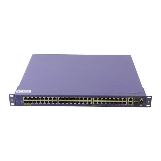
Page 43: Summit X450A-24Tdc Switch
Four combination ports (ports 21-24) using RJ-45 connectors and SFPs to provide 4 Gbps of copper ● or fiber connectivity For information about SFPs, see the Extreme Networks Pluggable Interface Modules Installation Guide. LEDs to indicate port status and switch operating conditions. ●... -
Page 44: Summit X450A-24X Switch
Four combination ports (ports 21-24) using RJ-45 connectors and SFPs to provide 4 Gbps of copper ● or fiber connectivity For information about SFPs, see the Extreme Networks Pluggable Interface Modules Installation Guide. LEDs to indicate port status and switch operating conditions. ●... - Page 45 Stack PSU-1 PSU-E Stack number indicator The rear panel of the Summit X450a-24x switch Slot for one of the following Summit option cards: ● Summit XGM2-2xn option card, which allows you to add up to two 10-Gigabit XENPAK modules ■...
-
Page 46: Summit X450A-24Xdc Switch
Four combination ports (ports 21-24). using RJ-45 connectors and SFPs to provide 4 Gbps of copper ● or fiber connectivity For information about SFPs, see the Extreme Networks Pluggable Interface Modules Installation Guide. LEDs to indicate port status and switch operating conditions. ●... -
Page 47: Summit X450A-48T Switch
Four combination ports (ports 45-48) using RJ-45 connectors and SFPs to provide 4 Gbps of fiber or ● copper connectivity For information about SFPs, see the Extreme Networks Pluggable Interface Modules Installation Guide. LEDs to indicate port status and switch operating conditions. ●... -
Page 48: Summit X450A-48Tdc Switch
Four combination ports (ports 45-48) using RJ-45 connectors and SFPs ● For information about SFPs, see the Extreme Networks Pluggable Interface Modules Installation Guide. LEDs to indicate port status and switch operating conditions. ● For a description of the LEDs and their operation, see Switch LEDs”... -
Page 49: Summit X450E Series Switches
The rear panel of the Summit X450a-48tDC switch Slot for one of the following Summit option cards: ● Summit XGM2-2xn option card, which allows you to add up to two 10-Gigabit XENPAK modules ■ Summit XGM2-2xf option card, which allows you to add up to two 10-Gigabit XFP modules ■... -
Page 50: Summit X450E-24P Switch
Four combination ports (ports 21-24) using RJ-45 connectors and SFPs to provide 4 Gbps of copper ● or fiber connectivity For information about SFPs, see the Extreme Networks Pluggable Interface Modules Installation Guide. NOTE All 24 ports can provide PoE power. -
Page 51: Summit X450E-48P Switch
Four combination ports (ports 45-48) using RJ-45 connectors and SFPs to provide 4 Gbps of copper ● or fiber connectivity For information about SFPs, see the Extreme Networks Pluggable Interface Modules Installation Guide. NOTE All 48 ports are capable of providing PoE power LEDs to indicate port status and switch operating conditions. -
Page 52: Summit X450E-48P Power Supplies
Summit X450e-48p Power Supplies The Summit X450e-48p switch is powered by both an internal power supply and an optional external redundant power supply system. Internal Power Supply. The internal Summit X450e-48p power supply is capable of 370 W of PoE power: 15.4 W supplied to each port for a 24-port configuration and 7.7 W supplied to each port for a 48-port... -
Page 53: Summit X450, X450A, And X450E Series Switch Leds
The EPS-C (External Power Supply Chassis) is shipped with the redundant power supply cable that connects to the redundant input connector on the rear of the switch. The EPS-C chassis can hold from one to three 600-Watt EPS-600LS (External Power Module) units. - Page 54 Summit Family Switches Table 10: LEDs on the Summit X450, X450a, and X450e Switches (Continued) Label or Type Management Port LED Stacking Port LED SFP 1G Port LED XENPAK 10G Port LED Additional Port LED meanings for PoE switches: Summit X450e-24p & Summit X450e-48p All front-panel ports Color/State Meaning...
-
Page 55: Chapter 2: Summit External Power Supplies (Eps)
Summit External Power Supplies (EPS) This chapter describes Extreme Networks external power supplies available for use with the Summit family switches. The chapter includes the following sections: Overview on page 55 ● EPS-160 External Power Module (with EPS-T) on page 56 ●... -
Page 56: External Power Module (With Eps-T)
EPS-160 External Power Module (with EPS-T) The EPS-160 External Power Module (Model 10907) is a modular power supply for use with the EPS-T chassis. You can use the EPS-160 as a redundant power supply with the following Extreme Networks switches: Summit X150-24t switch ●... -
Page 57: Eps-Ld External Power Supply Unit
(Figure 47 Figure 47: Redundant Power Cord Connector EPS-LD External Power Supply Unit You can use the Extreme Networks EPS-LD External Power Supply Unit (Model 45019) as a redundant power supply with the following Extreme Networks switches: Summit X450a-24t switch ●... -
Page 58: Eps-150Dc External Power Module (With Eps-T2)
18 of the National Electric Code, ANSI/NFPA 70. EPS-600LS External Power Module The EPS-600LS External Power Module (Model No. 10913) is a 600-watt redundant power supply unit. You can use the EPS-600LS as a redundant power supply with the following Extreme Networks switches: Summit X450e-48p switch ●... -
Page 59: Poe Redundant Power Configurations
You install one, two, or three EPS-600LS power modules in the EPS-C chassis (Model No. 10912) to build an external redundant power system for the Summit switch. A redundant power cable shipped with the EPS-C chassis provides the connection between the external power system and the redundant power input connector on the back of the switch. -
Page 60: Internal-To-External Psu Transfer
Internal PSU Failure with Single EPS-600LS Module. When an EPS-C with a single EPS-600LS is connected to the Summit X450e-48p or X250e-48p switch and the internal PSU fails, power is drawn from the EPS- 600LS without power interruption to the PoE connected devices. - Page 61 After an EPS-600LS unit is disconnected from its power source, it may be removed from the EPS-C. See “Removing an EPS-600LS Power Module” on page 115 d Disconnect the EPS-C from the switch. Summit Family Switches Hardware Installation Guide EPS-600LS External Power Module...
- Page 62 Summit External Power Supplies (EPS) Summit Family Switches Hardware Installation Guide...
-
Page 63: Part 2: Installing The Hardware
Installing the Hardware... -
Page 65: Chapter 3: Site Preparation
● After examining your physical site and verifying that all environment requirements are met, evaluate and compare your existing cable plant with the requirements of the Extreme Networks equipment to determine if you need to install new cables. Summit Family Switches Hardware Installation Guide Appendix A of this guide. -
Page 66: Meeting Site Requirements
Meeting power requirements ● To run your equipment safely, you must meet the specific power requirements for each switch and external power supply unit installed in the system. For power specifications of the switches, see the specific switch listings in... -
Page 67: Wiring Closet Considerations
Temperature Extreme Networks equipment generates a significant amount of heat. It is essential that you provide a temperature-controlled environment for both performance and safety. Install the equipment only in a temperature- and humidity-controlled indoor area that is free of airborne materials that can conduct electricity. -
Page 68: Humidity
Spacing Requirements and Airflow Be sure that cables and other equipment do not block the air intake or outflow on an Extreme Networks Summit family switch. It is best to have at least 3 inches (8 cm) of clear space in front of the air intake and outflow vents on the sides of the switch;... -
Page 69: Protective Grounding For The Rack
WARNING! Extreme Networks switches do not have a switch for turning power to the unit on and off. For systems using an AC power supply, power to the switch is disconnected by removing the wall plug from the electrical outlet. -
Page 70: Evaluating And Meeting Cable Requirements
● Radio Frequency Interference ● Cabling Standards Extreme Networks recommends using the Building Industry Consulting Service International (BICSI) Registered Communications Distribution Designer (RCDD), which is globally recognized as a standard in site planning and cabling. For information, go to: http://www.bicsi.org Cable Labeling and Record Keeping A reliable cable labeling system is essential when planning and installing a network. -
Page 71: Installing Cable
Assign a unique block of sequential numbers to the group of cables that run between each pair of ● wiring closets. Assign a unique identification number to each equipment rack. ● Identify all wiring closets by labeling the front panel of your Extreme Networks equipment and ● other hardware. Keep accurate and current cable identification records. ●... - Page 72 Site Preparation Figure 49: Properly Installed and Bundled Cable Cable managers supporting and directing cables Proper bundling of cables Adequate slack, and bend radius SPG_008 Summit Family Switches Hardware Installation Guide...
-
Page 73: Fiber Optic Cable
Fiber Optic Cable Fiber optic cable must be handled carefully during installation. Every cable has a minimum bend radius, for example, and fibers will be damaged if the cables are bent too sharply. It is also important not to stretch the cable during installation. We recommend that the bend radius for fiber optic cable equal 2 inches (5.08 cm) minimum for each 90-degree turn as shown in NOTE Kinks and sharp bends can destroy or impair the cable’s ability to convey light pulses accurately from one end of the... -
Page 74: Rj-45 Connector Jackets
1000BASE-T 100BASE-TX 10BASE-T Proprietary to Extreme Networks. Connections between two Extreme Networks 1000BASE-LX interfaces that use 10/125 μm single-mode fiber can use a maximum distance of 10,000 meters. RJ-45 Connector Jackets Use RJ-45 cable with connector jackets that are flush with the connector or that have connectors with a no-snag feature. -
Page 75: Radio Frequency Interference
Uninterruptible Power Supply Requirements ● PoE Devices When connecting power over Ethernet (PoE) devices to a PoE switch, all connections between the PoE device and the switch must remain within the same building and use a low-voltage power distribution system per IEEE 802.3af. -
Page 76: Ac Power Cable Requirements
If a power source fails, it will affect only the switch power supply to which it is connected. If all switch power supplies are connected to a single power source, the entire switch is vulnerable to a power source failure. -
Page 77: Uninterruptible Power Supply Requirements
An uninterruptible power supply (UPS) is a device that sits between a power supply (such as a wall outlet) and a device (such as a switch) to prevent outages, sags, surges, and bad harmonics from adversely affecting the performance of the device. -
Page 78: Ups Transition Time
UPS Transition Time Transition time is the time that is necessary for the UPS to transfer from utility power to full-load battery power. For Extreme Networks products, a transition time of less than 20 milliseconds is required for optimum performance. -
Page 79: Chapter 4: Installing Summit Family Switches
CAUTION Be sure that proper ESD controls are in use before switch maintenance is performed. This includes but is not limited to wrist straps that are grounded to the switch chassis and earth grounds. -
Page 80: Building A Summitstack Configuration
For example, if you follow the cabling recommendations presented in and configure the stack from the console on the switch at the top of the physical stack, the switches will be assigned numbers 1 through 8 from the top down. -
Page 81: About Redundancy
To resolve a dual-master condition, you must be able to log in to each severed stack segment, either over the management network (using the Ethernet management port on a switch in the segment) or through a direct console port connection to each switch in the segment. - Page 82 Installing Summit Family Switches Table 16: Recommended Order for Stacking Connections (8-Switch Stack) Slot Connect Stack Port 1 on Number this switch to . . . Slot 8 Port 2 Slot 1 Port 2 Slot 2 Port 2 Slot 3 Port 2...
-
Page 83: Connecting A Stacking Cable To A Stacking Port
BD_164A Connecting a Stacking Cable to a Stacking Port To connect a Summit stacking cable: 1 Align the cable connector with the stacking port connector on the back of the first switch (Figure 55). 2 Firmly press the cable connector into place on the mating stacking port connector. -
Page 84: Connecting The Console Port
To begin the software configuration for a new stack, you must have at least one console port connected. Connect a console to the console port of the switch that you intend to become the master of the stack. If you are going to configure redundancy, you may wish to connect to the console ports of all switches in the stack that you will configure to be master-capable. -
Page 85: Rack-Mounting A Summit Switch
● adequate ventilation. 6 Secure the switch with suitable screws (not provided). 7 Connect the switch to the redundant power supply (if applicable). For instructions on installing and connecting redundant power supplies, see Summit Family Switches Hardware Installation Guide Installing a Summit Family Switch... -
Page 86: Free-Standing And Desktop Mounting Of Multiple Switches
Summit family switches are supplied with four self-adhesive rubber pads. Apply the pads to the underside of each device by placing the pad in the marked area at each corner of the switch, ensuring that all corners aligned. You can safely place up to four Summit family switches on top of one another. -
Page 87: Connecting The Internal Dc Power Supply To The Dc Source Voltage
1 At one end of the wire, strip the insulation to expose 1/2 inch (12 mm) of bare wire. 2 Identify the grounding lug on the back of the switch. The grounding lug is next to the edge of the back panel, identified by the international symbol for earth ground. - Page 88 3 Insert the stripped wire into the grounding lug (see Figure 58 Figure 59). Figure 58: Attaching the Ground Wire to a Summit x450a Series Switch Grounding Ground wire SH_061_ground_switch Figure 59: Attaching the Ground Wire to a Summit X250e Series Switch...
-
Page 89: Connecting The Dc Wiring Harness To The Dc Source Voltage
WARNING! The Summit X450a-24tDC or Summit X450a-24xDC switch and rack must be connected to protective earth ground before installing any switch components. WARNING! Wiring the DC input power harness to your facilities DC source voltage must be performed by a qualified, licensed electrician. -
Page 90: Attaching The Dc Wiring Harness To The Dc Power Socket On The Switch
Be sure that the DC circuit is de-energized before you connect the DC wiring harness to the DC power socket. CAUTION Be sure that proper ESD controls are in use before switch maintenance is performed. This includes but is not limited to wrist straps that are grounded to the switch chassis and earth grounds. -
Page 91: Removing A Summit Dc-Powered Switch From A Rack
3 Disconnect the Summit switch from the redundant power supply (if applicable). 4 At the back of the switch, loosen the retaining screw on the ground lug and pull the ground wire out of the lug. Move the ground wire out of the way. -
Page 92: Initial Management Access
Initial Management Access When you take your switch from the box and set it up for the first time, you must connect to the console to access the switch and perform initial security configuration. At this time you can also manually configure an IP address for the default VLAN. - Page 93 NOTE For more information about logging in to the switch and configuring switch management access, see the ExtremeXOS 12.0 Concepts Guide. 5 At the password prompt, press [Return]. The default user name admin has no password assigned to it. When you have successfully logged on to the system, the command line prompt displays the system name (for example, its prompt.
- Page 94 Installing Summit Family Switches Summit Family Switches Hardware Installation Guide...
-
Page 95: Chapter 5: Installing Summit External Power Supplies
CAUTION Be sure that proper ESD controls are in use before switch maintenance is performed. This includes but is not limited to wrist straps that are grounded to the switch chassis and earth grounds. -
Page 96: Pre-Installation Requirements
Use proper overcurrent protection, such as a circuit breaker, to prevent overcurrent conditions. The switch and each redundant power supply source should be plugged into separate branch circuits to provide redundancy. -
Page 97: Installing An Eps-160 Power Supply Into An Eps-T
3 Insert the power supply into the empty slot on the EPS-T. 4 Tighten the captive thumbscrews to secure the power supply to the EPS-T. 5 Connect the EPS-160 power supply to the Summit switch, following the instructions in the EPS-160 Power Supply to the Switch” on page... - Page 98 1 Connect the keyed end of the redundant power supply cord to the EPS-160 power supply (see Figure 64). 2 Connect the other end of each EPS-160 power supply cord to the Extreme switch (see This connector end can only be inserted into the switch with the end marked TOP facing up. NOTE If your switch was shipped with a metal cover plate over the redundant power input connector, remove the cover.
-
Page 99: Removing An Eps-160 Power Supply From An Eps-T
EPS-LD facing either the front or the back of the rack. For this reason, each unit has two sets of mounting holes on each side. Extreme Networks recommends that you position the EPS-LD so that the power output connectors on the EPS-LD unit are on the same side as the external connector on the connecting switch. -
Page 100: Connecting The Eps-Ld To The Switch
4 Slide the EPS-LD into a 19-inch rack and secure it using appropriate rack-mount screws. NOTE Extreme Networks recommends that you position the EPS-LD so that the output connectors are on the same side as the external connector on the connecting switch. If you mount the EPS-LD with the connectors facing in the opposite direction from the Summit switch connector, leave at least 1 U between the switch and the EPS-LD through which to slide the power cords. -
Page 101: Connecting The Eps-Ld To Power
Make sure the EPS-LD is connected to the switch before you connect the AC power. CAUTION The EPS-LD does not have a switch for turning the unit on and off. You disconnect power to the EPS-LD by removing the plug from the electrical outlet. Make sure that this connection is easily accessible. -
Page 102: Removing An Eps-Ld
You can position the EPS-500 facing either the front or the back of the rack. For this reason, each unit has two sets of mounting holes on each side. Extreme Networks recommends that you position the EPS- 500 unit so that the power output connectors of the EPS-500 unit are on the same side as the external connector on the connecting switch. -
Page 103: Connecting The Eps-500 Power Supply
4 Slide the EPS-500 into a 19-inch rack and secure it using appropriate rack-mount screws.I NOTE Extreme Networks recommends that you position the EPS-500 so that the output connectors are on the same side as the external connector on the connecting switch. If you position the EPS-500 with the connectors facing in the opposite direction from the Summit switch connector, leave at least 1 u between the switch and the EPS- 500 through which to slide the power cords. - Page 104 CAUTION The EPS-500 unit does not have a switch for turning the unit on and off. Disconnect power to the EPS-500 unit by removing the plug from the electrical outlet. Be sure that this connection is easily accessible to you.
-
Page 105: Removing An Eps-500 Power Supply
The EPS-150DC power supply is a modular power supply for use in the EPS-T2 External Power System Tray. The EPS-T2 is a rack-mountable chassis or tray that holds one or two EPS-150DC power supplies. Each EPS-150DC provides one-to-one redundancy to an attached Extreme Networks switch. You must install the EPS-150DC power supply in the EPS-T2 tray. -
Page 106: Installing An Eps-150Dc Power Supply
Always be sure that the DC circuit is de-energized before connecting or disconnecting the DC wiring harness at the DC power socket on the rear of the EPS-150DC unit, and before connecting or disconnecting the redundant power cord between the switch and the EPS-150DC unit. Installing an EPS-150DC unit consists of the following tasks: Connecting the DC wiring harness to the DC source voltage (see ●... -
Page 107: Installing An Eps-150Dc Unit Into An Eps-T2
To install an individual EPS-150DC into an EPS-T2: 1 Attach an ESD-preventive wrist strap to your wrist and connect the metal end to the ground receptacle on the top right corner of the switch front panel. 2 Remove the EPS-150DC from the packing material. -
Page 108: Connecting The Dc Wiring Harness To The Dc Power Socket On The Eps-150Dc
3 Tighten the retainer nut on the connector until it is finger tight. Connecting the EPS-150DC to a Switch If you are connecting the EPS-150DC unit to a Summit X450a-48tDC switch, you must ground the switch before connecting power. For instructions on grounding the switch, see DC-Powered Switch”... - Page 109 4 Align and tighten the connector retaining screws to secure the cable connector to the power supply unit. 5 Connect the other end of the redundant power cord to the Extreme switch. The connector fits the slot in only one direction.
-
Page 110: Removing An Eps-150Dc Power Module
4 At each end of the redundant power cable, unscrew the captive retaining screws on the power connector and disconnect the cable from the switch and the EPS-150DC unit. 5 Loosen the thumbscrews on the front of the EPS-150DC unit until they are completely free of the EPS-T tray, and slide the EPS-150 unit out of the tray. -
Page 111: Installing An Eps-600Ls External Power Module
Each EPS-600LS power module is shipped with an AC cord for use in North America, and each EPS-C chassis is shipped with a special redundant power supply cord for connection to the Summit switch. Make sure that the EPS-C chassis is installed in the rack system before installing an EPS-600LS unit. - Page 112 The key is a plastic tab on the cable connector housing that fits into the EPS-C to ensure correct alignment of the connector. 6 Connect the other end of the redundant power cord to the Summit X450e-48p or X250e-48p switch (see Figure 78).
-
Page 113: Installing An Eps-600Ls Power Supply
Be sure that empty slots in the EPS-C chassis are always covered by a cover plate when not in use. The EPS-C is shipped with slots 2 and 3 covered and slot 1 open. Extreme Networks recommends that you populate slot 1 with an EPS-600LS unit first, but this is not required. - Page 114 CAUTION The EPS-600LS unit does not have a switch for turning the unit on and off. Disconnect power to the EPS-600LS unit by removing the plug from the electrical outlet. Make sure that this connection is easily accessible to you.
-
Page 115: Removing An Eps-600Ls Power Module
Installing an EPS-600LS External Power Module Be sure that the electrical outlet is properly grounded. 7 Repeat steps 1 through 6 for each EPS-600LS unit. Removing an EPS-600LS Power Module To manually disconnect an EPS-C or to remove the EPS-600LS modules, the recommended practice is to disconnect the EPS-600LS modules one at a time, pausing two seconds after each EPS-600LS disconnect. - Page 116 Installing Summit External Power Supplies Summit Family Switches Hardware Installation Guide...
-
Page 117: Chapter 6: Summit Option Cards
If the XFP or XENPAK module is too hot to touch, disengage the XFP or XENPAK module and allow it to cool before removing it completely. Only trained service personnel should perform service to Extreme Networks switches and their components. Trained service personnel have read all related installation manuals, have the technical training and experience necessary to be aware of the hazards to which they are exposed in performing a task, and are aware of measures to minimize the danger to themselves or other persons. -
Page 118: Summit Xgm-2Xn Option Card
Never look at the transmit LED/laser through a magnifying device while it is powered on. ● Never look directly at a fiber port on the switch or at the ends of a fiber cable when they are powered on. ●... -
Page 119: Installing The Summit Xgm-2Xn Option Card
● CAUTION Be sure that proper ESD controls are in use before switch maintenance is performed. This includes but is not limited to wrist straps that are grounded to the switch chassis and earth grounds. To install the Summit XGM-2xn card: 1 Disconnect the AC power and any redundant power supply from the Summit switch. -
Page 120: Summit Xgm2-2Xn Option Card
For information on installing or replacing the XENPAK modules in the Summit XGM-2xn option card, refer to the Extreme Networks Pluggable Interface Modules Installation Manual. NOTE If you install only one XENPAK module in the Summit XGM-2xn option card, attach the supplied cover plate over the remaining open module slot. -
Page 121: Installing The Summit Xgm2-2Xn Option Card
Summit XGM2-2xn option card. Figure 84: Summit XGM2-2xn Option Card NOTE Refer to the Extreme Networks Pluggable Interface Modules Installation Guide for more information about XENPAK modules. Standards-based CX-4 XENPAKs are also recognized by ExtremeXOS; contact your CX-4 module vendor to obtain these. -
Page 122: Summit Xgm2-2Xf Option Card
Figure 85: Option Slot Filler Panel 5 Align the sheet metal edges on the option card with the card guides in the switch housing. Carefully slide the Summit XGM2-2xn option card into the switch housing until the connectors engage and the... -
Page 123: Installing The Summit Xgm2-2Xf Option Card
Figure 87 shows the Summit XGM2-2xf option card. Figure 87: Summit XGM2-2xf Option Card NOTE Refer to the Extreme Networks Pluggable Interface Modules Installation Guide for more information about XFP modules. Installing the Summit XGM2-2xf Option Card CAUTION The Summit XGM2-2xf option card is not hot-swappable. Disconnect power to the switch before installing or removing the Summit XGM2-2xf option card. - Page 124 Figure 88: Option Slot Filler Panel 5 Align the sheet metal edges on the option card with the card guides in the switch housing. Carefully slide the Summit XGM2-2xf option card into the switch housing until the connectors engage and the...
- Page 125 Summit XGM2-2xf Option Card NOTE If you install only one XFP module in the Summit XGM2-2xf option card, attach the supplied cover plate over the remaining open module slot. Summit Family Switches Hardware Installation Guide...
- Page 126 Summit Option Cards Summit Family Switches Hardware Installation Guide...
- Page 127 Appendixes...
-
Page 129: Appendix A: Safety Information
Safety Information WARNING! Read the following safety information thoroughly before installing Extreme Networks products. Failure to follow this safety information can lead to personal injury or damage to the equipment. Only trained service personnel should perform service to Extreme Networks switches and their components. -
Page 130: Installing External Power Supply Units
Wiring a DC power cord to your facility DC source voltage must be performed by a qualified, licensed electrician. Extreme Networks AC external power supplies do not have switches for turning the unit on and off. Remove the wall plug from the electrical outlet to disconnect the power from an Extreme Networks AC external power supply. Make sure that this connection is easily accessible. -
Page 131: Maintenance Safety
EMC regulations. The chassis cover should only be removed by Extreme Networks personnel. There are no customer ● serviceable components in this system. Repairs to the system must be performed by an Extreme Networks factory service technician. -
Page 132: Poe Devices
IEEE 802.3af. Selecting Power Supply Cords Extreme Networks provides power input cords shipped in the product box for use in the US and Canada. Power supply cords for use outside of the United States and Canada are typically provided separately by third-party distribution centers. -
Page 133: Battery Replacement And Disposal
The power cord provided with the power supply, switch, or chassis is for use only with that ● specific product from Extreme Networks; it is not for use with any other product from Extreme Networks or any other vendors' equipment. -
Page 134: Sfp (Mini-Gbic), Xenpak, And Xfp Regulatory Compliance
Never look at the transmit LED/laser through a magnifying device while it is powered on. ● Never look directly at a fiber port on the switch or at the ends of a fiber cable when they are powered on. ●... -
Page 135: Hinweise Zur Installation
Sicherstellen, dass Ihre Netzteile die Anforderungen an die Strom- oder Wechselstromversorgung ● vor Ort für alle Netzwerkgeräte erfüllen. Bei den Extreme-Produkten handelt es sich um digitale Geräte der Klasse A gemäß Teil 15 der FCC- ● Richtlinien und anderen internationalen Richtlinien. Der Gerätebetrieb unterliegt den folgenden Voraussetzungen: (1) Das Gerät kann schädliche Interferenzen verursachen, und (2) das Gerät muss... -
Page 136: Installation Von Netzteilen
Das Gleichstromkabel des 325 W DC-Netzteils muss von einem qualifizierten, zugelassenen Elektriker an die Gleichspannungsquelle in Ihrem Gebäude angeschlossen werden. Extreme Networks 325 W AC Netzteile haben keinen An- Aus Schalter. Die Stromzufuhr zu einem Extreme Networks http://www.extremenetworks.com Summit Family Switches Hardware Installation Guide... -
Page 137: Allgemeine Sicherheitsvorkehrungen
Die Nichtbeachtung dieser Anweisungen kann zu Schäden an der Ausrüstung oder sogar zu einem Verstoß gegen die erforderlichen Sicherheitsbestimmungen und EMV-Vorschriften führen. Die Abdeckung der Grundplatte darf nur durch Personal von Extreme Networks entfernt werden. ● Das System enthält keine vom Kunden zu wartenden Komponenten. Reparaturen am System sind von einem Werkstechniker von Extreme Networks durchzuführen. - Page 138 Networks entweder nur mit einem 110-VAC-Kabel oder mit einem 110-VAC-Kabel und einem 208/220- VAC-Kabel geliefert. Die von Extreme Networks gelieferten Stromkabel sind nur für den Einsatz in den Vereinigten Staaten und Kanada ausgelegt und zugelassen. Stromkabel für den Einsatz außerhalb der Vereinigten Staaten und Kanada werden normalerweise von einem Drittanbieter geliefert und müssen...
- Page 139 Das mit dem Netzteil, dem Switch oder der Grundplatte gelieferte Verbindungskabel ist nur ■ für den Einsatz mit dem spezifischen Produkt von Extreme Networks vorgesehen und darf nicht mit anderen Geräten von Extreme Networks oder anderen Anbietern verwendet werden. Nordamerika: Versorgungssteckdose, 15 A, NEMA 5-15 für 110-VAC-Netzteile und NEMA L6-15P ●...
- Page 140 Safety Information Einhaltung behördlicher Vorschriften durch SFP (Mini-GBIC), XENPAK und XFP Laserprodukt der Klasse 1 ● EN60825-1+A2:2001 oder jünger, Europäische Richtlinie für Lasersysteme ● Anwendung der CE-Kennzeichnung gemäß der Richtlinien 89/336/EWG EMV und 73/23/EWG für ● Niederspannungsgeräte Summit Family Switches Hardware Installation Guide...
-
Page 141: Appendix B: Technical Specifications
Technical Specifications This appendix includes the following specifications for Summit switch series and related components: Summit X150 Series Switches on page 141 ● Summit X250e Series Switches on page 144 ● Summit X350 Series Switches on page 150 ● Summit X450 Series Switches on page 153 ●... - Page 142 Technical Specifications Table 23: Summit X150 Series Switch Technical Specifications (Continued) Summit X150-24t Power Operational voltage range Nominal input ratings Input current Line frequency range Inrush current Power supply cord type Power supply input socket Power cord input plug Power cord wall plug...
- Page 143 Table 23: Summit X150 Series Switch Technical Specifications (Continued) Heat dissipation (BTU) Heat dissipation (Watts) Power consumption (BTU) Power consumption (Watts) Safety Standards North American Safety of ITE European Safety of ITE International Safety of ITE EMI/EMC Standards North America EMC for ITE...
-
Page 144: Summit X250E Series Switches
Technical Specifications Table 23: Summit X150 Series Switch Technical Specifications (Continued) Environmental Data Environmental Standards Operating conditions Storage & transportation conditions (packaged) Acoustic noise (in dBA per ISO 7779) Summit X250e Series Switches The Summit X250e series includes the following switches: Summit X250e-24t switch ●... - Page 145 Table 24: Summit X250e Series Switch Technical Specifications (Continued) Weight Summit X250e-24t switch Summit X250e-24tDC Summit X250e-24p switch Summit X250e-24x Summit X250e-24xDC Summit X250e-48t switch Summit X250e-48tDC switch Summit X250e-48p switch Packaged Dimensions Summit X250e-24t switch Summit X250e-24tDC switch Summit X250e-24p switch...
- Page 146 Technical Specifications Table 24: Summit X250e Series Switch Technical Specifications (Continued) Summit X250e-24p Power Operational voltage range Nominal input ratings Input current Line frequency range Inrush current Power supply cord type Power supply input socket Power cord input plug Power cord wall plug...
- Page 147 Table 24: Summit X250e Series Switch Technical Specifications (Continued) Power cord wall plug Power supply cord gauge Efficiency Heat dissipation (Watts) Heat dissipation (BTU/hr) Power consumption (Watts) Power consumption (BTU/hr) Summit X250e-24tDC Power Operational voltage range Nominal input ratings Input current...
- Page 148 Technical Specifications Table 24: Summit X250e Series Switch Technical Specifications (Continued) Nominal input ratings Input current Line frequency range Inrush current Power supply cord type Power supply input socket Power cord input plug Power cord wall plug Power supply cord gauge...
- Page 149 Table 24: Summit X250e Series Switch Technical Specifications (Continued) EMI/EMC Standards North America EMC for ITE European EMC standards International EMC certifications Country-specific Telecom Standards IEEE 802.3 Media Access Standards Environmental Data Environmental Standards Operating conditions Storage & transportation conditions...
-
Page 150: Summit X350 Series Switches
Technical Specifications Table 24: Summit X250e Series Switch Technical Specifications (Continued) Acoustic noise (in dBA per ISO 7779) Summit X350 Series Switches The Summit X350 series includes the following switches: Summit X350-24t ● Summit X350-48t ● Table 25: Summit X350 Series Switch Technical Specifications... - Page 151 Table 25: Summit X350 Series Switch Technical Specifications (Continued) Summit X350-24t Power Operational voltage range Nominal input ratings Input current Line frequency range Inrush current Power supply cord type Power supply input socket Power cord input plug Power cord wall plug...
- Page 152 Technical Specifications Table 25: Summit X350 Series Switch Technical Specifications (Continued) EMI/EMC Standards North America EMC for ITE European EMC standards International EMC certifications Country-specific Telecom Standards IEEE 802.3 Media Access Standards Environmental Data Environmental Standards Operating conditions Storage & transportation conditions...
-
Page 153: Summit X450 Series Switches
The Summit X450 series includes the following switches: Summit X450-24t switch ● Summit X450-24x switch ● Table 26: Summit X450 Series Switch Technical Specifications Physical Dimensions Summit X450-24t switch Height: 1.73 inches (4.4 cm) Summit X450-24x switch Width: 17.35 inches (44.1 cm) Depth: 16.38 inches (41.6 cm) -
Page 154: Summit X450A Series Switches
Technical Specifications Table 26: Summit X450 Series Switch Technical Specifications (Continued) International EMC certifications Country-specific Telecom Standards Environmental Data Environmental standards Operating conditions Storage & transportation conditions (packaged) Acoustic Sound (Summit X450-24t and SummitX450-24x) Sound power in accordance with EN 300 753 (10-1997) - Page 155 Table 27: Summit X450a Series Switch Technical Specifications Physical Dimensions Summit X450a-24t switch Summit X450a-24tDC switch Summit X450a-24x switch Summit X450a-24xDC switch Summit X450a-48t switch Summit X450a-48tDC switch Weight Summit X450a-24t switch Summit X450a-24tDC switch Summit X450a-24x switch Summit X450a-24xDC switch...
- Page 156 Technical Specifications Table 27: Summit X450a Series Switch Technical Specifications (Continued) Nominal input current Inrush current Power supply cord type Power supply input socket Power cord input plug Power cord wall plug Power supply cord gauge Heat dissipation, Watts, BTU Power consumption, Watts, BTU Summit X450a-48t Power &...
- Page 157 Table 27: Summit X450a Series Switch Technical Specifications (Continued) Power supply cord gauge Heat dissipation, Watts, BTU Power consumption, Watts, BTU Summit X450a-24xDC Power Operational voltage range Nominal input ratings Input current Power supply cord type Power supply input socket...
-
Page 158: Summit X450E Series Switches
Technical Specifications Table 27: Summit X450a Series Switch Technical Specifications (Continued) Telecom Standards IEEE 802.3 Media Access Standards Environmental Data Environmental standards Operating conditions Storage & transportation conditions (packaged) Sound power in accordance with EN 300 753 (10-1997) Summit X450a-24t and X450a-48t... - Page 159 Table 28: Summit X450e Series Switch Technical Specifications (Continued) Summit X450e-48p switch Packaged Dimensions Summit X450e-24p switch Summit X450e-48p switch Packaged Weight Summit X450e-24p switch Summit X450e-48p switch Summit X450e-24p Power Operational voltage range Nominal input ratings Input current Line frequency range...
- Page 160 Technical Specifications Table 28: Summit X450e Series Switch Technical Specifications (Continued) International Safety of ITE EMI/EMC Standards North America EMC for ITE European EMC standards International EMC certifications Country-specific Telecom Standards IEEE 802.3 Media Access Standards Environmental Data Environmental standards Operating conditions Storage &...
-
Page 161: Summit External Power Supplies
Summit External Power Supplies The following external power supplies are available for use with Summit family switches: EPS-LD external power supply ● EPS-160 external power module (used with EPS-T chassis) ● EPS-500 external power supply ● EPS-600LS external power module (used with EPS-C chassis) ●... - Page 162 Technical Specifications Table 30: EPS-160 External Power Module (Model 10907) (Continued) Power supply input plug Power cord wall plug Power supply cord gauge Efficiency Heat dissipation, Watts/BTU Power consumption, Watts, BTU/hr Ambient operating temperature Table 31 shows the wire-to-pin connections for the connector on the rear panel of the EPS-160 power supply.
- Page 163 Table 33: EPS-600LS External Power Module (Model 10913) For use with the Summit X450e-48p and X250e-48p switches Must be installed in the EPS-C chassis (Model 10912) Operational voltage range Nominal input ratings Nominal input current Line frequency range Maximum inrush current Output power Power supply cord type Power supply input socket...
- Page 164 Technical Specifications Table 34: EPS-150DC External Power Module (Model 10909) For use with the Summit X450a-24tDC and Summit X450a-24xDC switches Operational voltage range Nominal input ratings Input current Line frequency range Inrush current Input wire harness Power supply input socket...
-
Page 165: Console Connector Pinouts
RTS (request to send) CTS (clear to send) Figure 91 shows the pinouts for a 9-pin to 25-pin (RS-232) null-modem cable. Figure 91: Null-Modem Cable Pinouts Switch Cable connector: 9-pin female Screen Shell Ground Summit Family Switches Hardware Installation Guide... - Page 166 Technical Specifications Figure 92 shows the pinouts for a 9-pin to 9-pin (PC-AT) null-modem serial cable. Figure 92: PC-AT Serial Null-modem Cable Pinouts Switch Cable connector: 9-pin female Screen Shell Ground PC/Terminal Cable connector: 25-pin male/female Screen Ground 25pin Summit Family Switches Hardware Installation Guide...
-
Page 167: Index
68 temperature, 67 wiring closet, 67 EPS-150DC power supply features, 58 installing, 105 specifications, 164 with Summit X450a-24tDC switch, 24, 28, 30, 44 with Summit X450a-24xDC switch, 46 with Summit X450a-48tDC switch, 49 EPS-160 power supply features, 56 installing, 96... - Page 168 Index with Summit X450-24t switch, 35, 39 with Summit X450-24x switch, 41 EPS-500 power supply features, 57 installing, 102 specifications, 162 with Summit X450a-48t switch, 36, 48 with Summit X450e-24p switch, 50 EPS-600LS power supply features, 58 installing, 111 specifications, 163...
- Page 169 EPS-500 power supply, 162 EPS-600LS power supply, 163 EPS-LD power supply, 161 power cable, 76 Summit X150 series switches, 141 Summit X250e series switch, 144 Summit X450 series switches, 153 Summit X450a series switches, 155 Summit X450e series switches, 158 stack master, 81...
- Page 170 Summit X450-24x switch, 40 Summit X450a series switches features, 41 LEDs, 53 specifications, 155 Summit X450a-24t switch, 42 Summit X450a-24tDC switch, 43 Summit X450a-24x switch, 44 Summit X450a-24xDC switch, 46 Summit X450a-48t switch, 47 Summit X450a-48tDC switch, 48 Summit X450a-48t switch, removing, 91...