Table of Contents
Advertisement
Quick Links
Advertisement
Table of Contents

Related Manuals for Encore ENHWI-G


Summary of Contents for Encore ENHWI-G
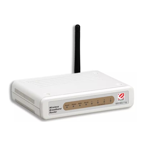
- Page 1 ENHWI-G IEEE 802.11g Wireless Broadband Router User Guide...
- Page 2 Regulatory notes and statements Wireless LAN, Health and Authorization for use Radio frequency electromagnetic energy is emitted from Wireless LAN devices. The energy levels of these emissions however are far much less than the electromagnetic energy emissions from wireless devices like for example mobile phones.
-
Page 3: Fcc Interference Statement
The radiated output power of this Wireless LAN device is far below the FCC radio frequency exposure limits. Nevertheless, this device shall be used in such a manner that the potential for human contact during normal operation is minimized. When nearby persons has to be kept to ensure RF exposure compliance, in order to comply with RF exposure limits established in the ANSI C95.1 standards, the distance between the antennas and the user should not be less than 20 cm. -
Page 4: Ce Mark Warning
The antenna(s) used for this transmitter must be installed to provide a separation distance of at least 20 cm from all persons and must not be co-located or operating in conjunction with any other antenna or transmitter. CE Mark Warning This is a Class B product. -
Page 5: Table Of Contents
TABLE OF CONTENT ... 1 BOUT UIDE Purpose ... 1 Overview of this User’s Guide ... 1 ... 2 NTRODUCTION Applications:... 2 Features: ... 3 NPACKING AND ETUP Unpacking ... 4 Setup... 4 ARDWARE NSTALLATION Front Panel ... 5 Rear Panel... 5 Hardware connections ... - Page 6 2.2.1 Basic ... 24 2.2.2 Authentication ... 25 2.2.3 Advanced... 27 2.3 Status... 27 2.3.1 Device Information... 28 2.3.2 Log... 28 2.3.3 Log Setting ... 30 2.3.4 Statistic ... 31 2.3.5 Wireless ... 32 2.4 Routing... 33 2.4.1 Static ... 33 2.4.2 Dynamic ...
-
Page 7: About This Guide
Identifying External Components. Describes the front panel, rear panel and LED indicators of the Wireless Router. Connecting the Router. Tells how you can connect the Wireless Router to your xDSL/Cable Modem. Technical Specifications. Lists the technical (general, physical and environmental,... -
Page 8: Introduction
INTRODUCTION With the explosive growth of the Internet, accessing information and services at any time, day or night has become a standard requirement for most people. The era of the standalone PC is waning. Networking technology is moving out of the exclusive domain of corporations and into homes with at least two computers. -
Page 9: Features
Features: High speed data transfer rate Supports NAT for share 1 IP address to all LAN user. Supports PPPoE and PPTP protocol for Dial-Up ADSL. Supports 64/128 bit WEP Encryption Supports WPA security Supports DHCP Server / Client. Supports UPnP (Universal Plug and Play). Supports virtual server mapping. -
Page 10: Unpacking And Setup
Broadband Router. Do not place heavy objects on the Broadband Router. Fix the direction of the antennas. Try to place the Wireless Router in a position that can best cover your wireless network. Normally, the higher you place the antenna, the better the performance will be. -
Page 11: Hardware Installation
WLAN (ACT) This indicator lights green when there are wireless devices connected and transmitting data to the Wireless Router. LAN (Link/ACT) These indicators light green when the LAN ports were connected successfully. These indicators blink green while the LAN ports were transmitting data. -
Page 12: Hardware Connections
Antenna There are two 2 dBi Gain Antenna in the rear panel for wireless connection. LAN (1-4) Four RJ-45 10/100Mbps Auto-MDIX ports for connecting to either 10Mbps or 100Mbps Ethernet connections. In the four port broadband router, there is an RJ-45 10/100Mbps Auto-MDIX port for the WAN that will fit the xDSL/Cable modem’s specification need. -
Page 13: Connect The Router Using Wireless Lan
Connect the Router using Wireless LAN 1. Plug in one end of the RJ45 network cable to the xDSL/Cable Modem. 2. Plug in the other end of the RJ45 network cable to the Wireless Internet Broadband Router WAN port. Check the installation The control LEDs of the Wireless Internet Broadband Router are clearly visible and the status of the network link can be seen instantly: 1. -
Page 14: Pc Network Tcp/Ip Setting
PC NETWORK TCP/IP SETTING The network TCP/IP settings differ based on the computer’s operating system (Win95/98/ME/NT/2000/XP) and are as follows. Windows 95/98/ME 1. Click on the “Network neighborhood” icon found on the desktop. 2. Click the right mouse button and a context menu will be show. 3. -
Page 15: Windows 2000
6. Select “None” for the “Gateway address” field. Windows 2000 Double click on the “My computer” icon on the desktop. When “My computer” window opens, open the “Control panel” and then open the “Network dialup connection” applet. Double click on the “Local area network connection” icon. Select “Properties”... -
Page 16: Windows Xp
Windows XP Point the cursor and click the right button on the “My Network Place” icon. Select “properties” to enter the TCP/IP setting window. 1. Set “IP address” to “Obtain an IP address automatically.” 2. Set “DNS” to “Obtain DNS server address automatically.”... -
Page 17: Wireless Broadband Router Configuration
WIRELESS BROADBAND ROUTER CONFIGURATION First make sure that the network connections are functioning normally. This Wireless Broadband Router can be configured using Internet Explorer 4.0 or newer web browser versions. Login to the Wireless Broadband Router through WLAN Before configuring the Wireless Broadband Router through WLAN, make sure that the SSID, Channel and the WEP is set properly. -
Page 18: Quick Setup
Setup wizard is provided as the part of the web configuration utility. User can simply follow the step-by-step process to get the wireless router configuration ready to run in 6 easy steps by clicking on the “Wizard” button on the function menu. - Page 19 Step 2: Choose time zone Select the time zone from the drop down list. Please click “Next” to continue. Step 3: Set LAN connection and DHCP server Set user’s IP address and mask. The default IP is 192.168.1.1. If user likes to enable DHCP, please click “Enabled”.
- Page 20 Step 4: Set Internet connection Select how the router will set up the Internet connection: Obtained IP automatically; Fixed IP address; PPPoE to obtain IP automatically; PPPoE with a fixed IP address; PPTP. Obtain IP automatically (DHCP client): If user has enabled DHCP server, choose "Obtain IP automatically (DHCP client)" to have the router assign IP addresses automatically.
- Page 21 If the Internet Service Providers assign a fixed IP address, choose this option and enter the assigned IP address, subnet mask, gateway IP and DNS IP addresses for your Broadband Router.
- Page 22 PPPoE to obtain IP automatically: If connected to the Internet using a PPPoE (Dial-up xDSL) Modem, the ISP will provide a Password and User Name, and then the ISP uses PPPoE. Choose this option and enter the required information.
- Page 23 PPPoE with a fixed IP address: If connected to the Internet using a PPPoE (Dial-up xDSL) Modem, the ISP will provide a Password, User Name and a Fixed IP Address, choose this option and enter the required information.
- Page 24 PPTP: If connected to the Internet using a (PPTP) xDSL Modem, enter the your IP Address, Subnet Mask, Gateway, Server IP, PPTP Account and PPTP Password, Your Subnet Mask required by your ISP in the appropriate fields. If your ISP has provided you with a Connection ID, enter it in the Connection ID field, otherwise, leave it zero.
- Page 25 The Setup wizard is now completed. The new settings will be effective after the Wireless router restarted. Please click “Restart” to reboot the router. If user does not want to make any changes, please click “Exit” to quit without any changes.
-
Page 26: Advance Setup
Advance Setup LAN Setting The screen enables user to configure the LAN & DHCP Server, set WAN parameters, create Administrator and User passwords, and set the local time, time zone, and dynamic DNS. 2.1.1 LAN & DHCP Server This page leads to set LAN and DHCP properties, such as the host name, IP address, subnet mask, and domain name. -
Page 27: Wan
Start IP: Type an IP address to serve as the start of the IP range that DHCP will use to assign IP addresses to all LAN devices connected to the router. End IP: Type an IP address to serve as the end of the IP range that DHCP will use to assign IP addresses to all LAN devices connected to the router. -
Page 28: Password
2.1.3 Password This screen enables user to set administrative and user passwords. These passwords are used to gain access to the router interface. Administrator: Type the password the Administrator will use to log in to the system. The password must be typed again for confirmation. -
Page 29: Time
2.1.4 Time This screen enables user to set the time and date for the router's real-time clock, select properly time zone, and enable or disable daylight saving. Local Time: Displays the local time and date. Time Zone: Select the time zone from the drop-down list. Daylight Saving: Enables user to enable or disable daylight saving time. -
Page 30: Wireless
Wireless This section enables user to set wireless communications parameters for the router's wireless LAN feature. 2.2.1 Basic This page allow user to enable and disable the wireless LAN function, create a SSID, and select the channel for wireless communications. Enable/Disable: Enables and disables wireless LAN via the router. -
Page 31: Authentication
2.2.2 Authentication This screen enables user to set authentication type for secure wireless communications. Open System allows public access to the router via wireless communications. Shared Key requires the user to set a WEP key to exchange data with other wireless clients that have the same WEP key. This router also supports WPA and WPA-PSK. - Page 32 If WPA is selected, the below screen is shown. Please set the length of the encryption key and the parameters for the RADIUS server. RADIUS Server: 1. Enter the IP address of and the Port used by the Primary Radius Server Enter the Shared Secret, which is used by the Radius Server.
-
Page 33: Advanced
2.2.3 Advanced This screen enables user to configure advanced wireless functions. Beacon Interval: Type the beacon interval in the text box. User can specify a value from 1 to 1000. The default beacon interval is 100. RTS Threshold: Type the RTS (Request-To-Send) threshold in the text box. This value stabilizes data flow. -
Page 34: Device Information
2.3.1 Device Information This screen enables user to view the router LAN, Wireless and WAN configuration. Firmware Version: Displays the latest build of the router firmware interface. After updating the firmware in Tools - Firmware, check this to ensure that the firmware was successfully updated. - Page 35 Click “Last Page” to view the final page of the log Click “Previous Page” to view the page just before the current page Click “Next Page” to view the page just after the current page Click “Clear Log” to delete the contents of the log and begin a new log Click “Refresh”...
-
Page 36: Log Setting
2.3.3 Log Setting This screen enables user to set router logging parameters. SMTP Server: Type the SMTP server address for the email that the log will be sent to in the next field. Send to: Type an email address for the log to be sent to. Click “Email Log Now” to immediately send the current log. -
Page 37: Statistic
2.3.4 Statistic This screen displays a table that shows the rate of packet transmission via the router LAN and WAN ports (in bytes per second). Click “Reset” to erase all statistics and begin logging statistics again. -
Page 38: Wireless
2.3.5 Wireless This screen enables user to view information about wireless devices that are connected to the wireless router. Connected Time: Displays how long the wireless device has been connected to the LAN via the router. MAC Address: Displays the devices wireless LAN interface MAC address. -
Page 39: Routing
Routing This selection enables user to set how the router forwards data: Static and Dynamic. Routing Table enables user to view the information created by the router that displays the network interconnection topology. 2.4.1 Static It enables user to set parameters by which the router forwards data to its destination if user’s network has a static IP address. -
Page 40: Dynamic
Delete: Select one of the entries in the static IP address table at the bottom of the page and click “Delete” to remove the entry. New: Click “New” to clear the text boxes and add required information to create a new entry. -
Page 41: Routing Table
2.4.3 Routing Table This screen enables user to view the routing table for the router. The routing table is a database created by the router that displays the network interconnection topology. Network Address: Displays the network IP address of the connected node. Network Mask: Displays the network (subnet) mask of the connected node. -
Page 42: Access
Access This page enables user to define access restrictions, set up protocol and IP filters, create virtual servers, define access for special applications such as games, and set firewall rules. 2.5.1 MAC Filters Enables user to allow or deny Internet access to users within the LAN based upon the MAC address of their network interface. -
Page 43: Protocol Filter
Update: Click to update information for the user, if user has changed any of the fields. Delete: Select a user from the table at the bottom of the list and click “Delete” to remove the user profile. New: Click “New” to erase all fields and enter new information. 2.5.2 Protocol Filter This screen enables user to allow and deny access based upon a communications protocol list the user creates. - Page 44 Enable: Click to enable or disable the IP address filter. Range Start: Type the minimum address for the IP range. IP addresses falling between this value and the Range End are not allowed to access the Internet. Range End: Type the minimum address for the IP range. IP addresses falling between this value and the Range Start are not allowed to access the Internet.
-
Page 45: Virtual Server
2.5.4 Virtual Server This screen enables user to create a virtual server via the router. If the router is set as a virtual server, remote users requesting Web or FTP services through the WAN are directed to local servers in the LAN. The router redirects the request via the protocol and port numbers to the correct LAN server. -
Page 46: Special Ap
Update: Click to update information for the virtual server if user have selected a list item and have made changes. Delete: Select a list item and click “Delete” to remove the item from the list. New: Click “New” to erase all fields and enter new information. 2.5.5 Special AP This screen enables user to specify special applications, such as games, that require multiple connections that are inhibited by NAT. -
Page 47: Dmz
● Protocol: Select the protocol (TCP, UDP, or ICMP) that can be used to access the application. ● Port Range: Type the port range that can be used to access the application in the text boxes. ● Incoming: Defines which incoming communications users are permitted to connect with. -
Page 48: Firewall Rule
Enable: Click to enable or disable the DMZ. DMZ Host IP: Type a host IP address for the DMZ. The computer with this IP address acts as a DMZ host with unlimited Internet access. Apply: Click to save the settings. 2.5.7 Firewall Rule This screen enables user to set up the firewall. - Page 49 Destination: Defines the destination of the incoming packet that the rule is applied ● Interface: Select which interface (WAN or LAN) the rule is applied to. ● IP Range Start: Type the start IP address that the rule is applied to. ●...
-
Page 50: Management
Management Management enables user to set up Remote Management feature. 2.6.1 Remote Management This screen enables user to set up remote management. Using remote management, the router can be configured through the WAN via a Web browser. A user name and password are required to perform remote management. -
Page 51: Tools
Tools This page enables user to restart the system, save and load different settings as profiles, restore factory default settings, run a setup wizard to configure router settings, upgrade the firmware, and ping remote IP addresses. 2.7.1 Reset Click “Restart” to restart the system in the event the system is not performing correctly. - Page 52 2.7.2 Settings This screen enables user to save settings as a profile and load profiles for different circumstances. User can also load the factory default settings, and run a setup wizard to configure the router and router interface. Save Settings: Click “Save” to save the current configuration as a profile that can load when necessary.
- Page 53 2.7.3 Firmware This screen enables user to keep the router firmware up to date. Please follow the below instructions: Download the latest firmware from the manufacturer's Web site, and save it to disk. Click “Browse” and go to the location of the downloaded firmware file. Select the file and click “Upgrade”...
- Page 54 2.7.4 Ping Test The ping test enables user to determine whether an IP address or host is present on the Internet. Type the host name or IP address in the text box and click Ping.
-
Page 55: Technical Specifications
TECHNICAL SPECIFICATIONS Standards Protocol Radio Technology Data Transfer Rate Topology Receiver Sensitivity TX Power Network Cables Frequency Range Modulation Schemes Security Channels Number of Ports DC inputs Power Consumption Temperature Humidity Dimensions EMI: General IEEE 802.3u 100BASE-TX Fast Ethernet IEEE 802.11g; IEEE 802.11b CSMA/CD IEEE 802.11g Orthogonal Frequency Division Modulation 802.11b: 1, 2, 5.5, 11Mbps (auto sense)