Table of Contents
Advertisement
Advertisement
Table of Contents

Related Manuals for Encore ENMGS-24+4


Summary of Contents for Encore ENMGS-24+4
-
Page 1: User Guide
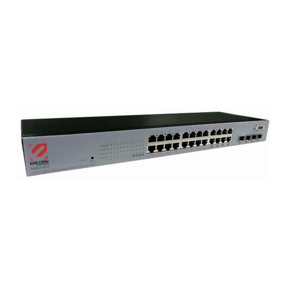
ENMGS-24+4 24 Port Gigabit Web Smart Switch w/ 4 port mini GBIC User Guide... -
Page 2: Fcc Certifications
FCC Certifications This Equipment has been tested and found to comply with the limits for a Class A digital device, pursuant to part 15 of the FCC Rules. These limits are designed to provide reasonable protection against harmful interference when the equipment is operated in a commercial environment. -
Page 3: Table Of Contents
Table of Contents UNPACKING INFORMATION INTRODUCTION ...4 ENERAL ESCRIPTION ...5 EATURES ...5 RONT ANEL LEDs Definition ...5 ...7 ANEL INSTALLATION ESKTOP NSTALLATION ... 8 MOUNT NSTALLATION NSTALLING ETWORK ABLES FUNCTIONAL DESCRIPTION UMBO RAME ... 10 ONTROL AND IRROR ... 10 VLAN ... - Page 4 ... 27 ISCOVERY ... 28 TATISTICS VERVIEW ... 28 ETAILED TATISTICS ... 29 ESTART ... 29 ACTORY EFAULT ... 29 MART ... 30 OFTWARE PLOAD PRODUCT SPECIFICATIONS APPENDIX- COMMAND LINE INTERFACE TART UP AND ERMINAL CONFIGURATION OGIN OGOUT ROCEDURES ... 33 OMMAND IERARCHY ...
-
Page 5: Unpacking Information
Unpacking Information Thank you for purchasing the 16/24-Port Gigabit Web Smart Switch with 4-Port Mini-GBIC. Before you start, please verify that your package contains the following items: 1. One 16/24-Port Gigabit Web Smart Switch with 4-Port Mini-GBIC 2. One power cord 3. -
Page 6: Key Features
The Front Panel The front panel consists of the ports and LED indicators. Please refer to the following paragraph for information. LEDs Definition LED for the device: The switch provides a power LED for the device. Steady Green Power Status Operation... - Page 7 LED for each port: The switch provides one “1000M” LED and one “10/100M” LED for each port. 1000M LED: Shows the current transmitting/receiving speed of the port. 10/100M LED: Shows the link status and the activities on the port. Status...
-
Page 8: The Rear Panel
240VAC, 50/60Hz. Please make sure that your outlet standard to be within this range. To power on the switch, please plug the female end of the power cord firmly into the receptacle of the switch and the other end into an electric service outlet. -
Page 9: Installation
Installation This switch can be placed on your desktop directly, or mounted in a rack. Please refer to the instructions for installation. Before installing the switch, we recommend: The switch is placed with appropriate ventilation environment. A minimum 25mm space around the unit is recommended. -
Page 10: Installing Network Cables
1. Crossover or straight-through cable: All the ports on the switch support Auto-MDI/MDI-X crossover cables can be used as the media to connect the switch with PCs as well as other devices like switches, hubs or router. 2. Category 3,4,5 or 5eUTP/STP cable: To make a valid connection and obtain the optimal performance. -
Page 11: Functional Description
Functional Description Jumbo Frame With Jumbo Frame supported, it is allowed for the switch to transport identical data in fewer frames. Hence helps to ensure fewer overheads, shorten processing time, and reduce interrupts. Note: To enable Jumbo Frame, Flow Control should be enabled in advance. -
Page 12: Management Guide
Manage the device via WEB browser To access the Web-based management interface, you should configure the management station with an IP address and subnet mask that compatible to your switch. The factory default value of the switch: IP: Subnet Mask: Default Gateway:... - Page 13 1. Running your Web Browser and enter the IP address “192.168.1.1” in the Address field. 2. Key in the user name and password to pass the authentication. The factory default value of User Name and Password is “admin”.
-
Page 14: Homepage
Homepage After authentication procedure, the “SYSTEM Configuration” page shows up as the Homepage. You may click the hyperlinks on the left side of each page to get access to each management functions. -
Page 15: System
System The System window provides the switch information and allows users to configure the switch properties. Items MAC Address The MAC address of this device.. S/W Version The software version of this device. IP Address Setup the IP address of the switch... -
Page 16: Port
Port This Port Configuration page shows the link status of each port and allows users to configure speed, flow control and Max frame size for each port. Items Link Shows the link status of each port. The column lights green with the link speed while there is valid connection on this port. - Page 17 functioning. Flow Control Mark the checkbox to enable the FDX Flow control, or unmark to disable. Max Frame length To adjust the size of Jumbo Frame. The length is 1518 bytes. The Maximum value can be up to 9216 bytes. To save the configuration of the system, click “Apply”...
-
Page 18: Vlan
VLAN VLAN divides the network members into groups to reduce packets collisions and improve the network efficiency. The switch supports 802.1Q tag-based VLAN. Please follow the instructions to configure. To add new VLAN groups, 1. Fill in a VLAN id from 2 to 4094 in the “VLAN\Port” column. - Page 19 Note: 1. When a port is configured to a specific VLAN group, a PVID that corresponding to the VLAN id will be assigned automatically to this port. (Ex, when you make port 3 of a VLAN with VLAN id “2”, the PVID “...
-
Page 20: Pvid
PVID When the VLAN-enabled switch receives a tagged packet, the packet will be sent to the port’s default VLAN according to the PVID (port VLAN ID) of the receiving port. Items Port Port Number 1~16/24 Egress Select “tagged” in the drop list to enable the PVID checking and tag inserting of one port, and select “untagged”... -
Page 21: Aggregation/ Trunk Configuration
Aggregation/ Trunk Configuration To set up the Port trunk groups, put the ports number into the same Aggregation group. There are eight groups to choose. Don’t forget to click the “Apply” to save the setting. There are three aggregation modes for you to setup, SMAC, DMAC, and XOR. SMAC mode selects the path of packets according to source MAC while DMAC mode selects path according to destination MAC. -
Page 22: Quality Of Service
Quality of Service QoS enhances the communication quality by giving different precedence to classified packets. This switch provides port-based, tag-based and DSCP QoS modes: Port-based mode QoS: The port-based QoS allows users to configure certain ports as high or low priority. - Page 23 Tag based QoS: The Tag based QoS decides packet priority according to the tags that adding on the packets. To configure Tag Based QoS configuration: Select “Tagged” in the “Mode” column for those ports that are going to perform tag-based QoS. Click the “Apply” button. Click the “Tag priority”...
- Page 24 DSCP mode QoS: The DSCP mode QoS gives packet priority by the types of the incoming packets. We distinguish those packets according to the “Delay”, “Throughput” and “Reliability” information attaching on the packet. The types are listed as the following table: Bit 0 (Delay) Bit 1 (Throughput) 0 (Normal)
-
Page 25: Mirror
Mirror The Mirror function copies all the packets that are transmitted by the source port to the destination port. It allows administrators to analyze and monitor the traffic of the monitored ports. Mirror Configuration: 1. Select those ports that are going to be monitored by marking the checkboxes in “Monitor Port”... -
Page 26: Rate Limit
Rate Limit This “Rate Limit” page allows users to limit the bandwidth for each port and configure the rules for Storm Control, which limits the flow of broadcast and multicast To perform storm control: 1. Click on each drop list to specify a speed for each frame type. 2. -
Page 27: Snmp
SNMP This device supports SNMP-management, which allows network administrators to monitor and configure this device with SNMP software. To allow this device to be managed via SNMP: 1. Select “enable” in the drop list. 2. Specify a trap IP. A trap IP is the destination port for sending trap information, which is usually the IP address of network administrators. -
Page 28: Discovery
Discovery After installing series of our switches, the discovery management tool helps users to search and get access to those switches within the LAN. Note. The discovery tool lists the Maximum 16 devices respectively for auto and manual modes. Auto Search 1. -
Page 29: Statistics Overview
Statistics Overview The Statistics Overview is provided for users to see the general transmitting and receiving status of each port. You may click the “Clear” button to clean all statistics or click the “Refresh” button to renew the statistics. Detailed Statistics The Detailed Statistics is provided for users to see the detailed transmitting and receiving status of each port. -
Page 30: Restart
Restart Restart: To restart the system, click the “Yes” button. The system restarts and shows the authentication window. Please fill in the username and password to continue. Factory Default Restore Factory Default: To restore the factory default value, click the Yes button. Note: The IP address of the device will also be configured as factory-default setting, which is 192.168.1.1. -
Page 31: Software Upload
Software Upload This “Software Upload” page allows users to upgrade firmware for this switch. To perform firmware upgrade: 1. Click the “Browse” button 2. Locate the firmware file 3. Click the “Upload” button to execute. Note: This new firmware is going to be applied on the other flash that you select in “Smart Boot”, that is, the new firmware is going to be applied on... -
Page 32: Product Specifications
Product Specifications Standard IEEE802.3 10BASE-T IEEE802.3u 100BASE-TX IEEE802.3x full-duplex operation and flow control IEEE802.3ab/z 1000BASE-T IEEE802.1Q VLAN interoperability IEEE802.1p Priority Operation Interface 16/24* 10/100/1000Mbps auto MDI/MDI-X RJ-45 switching ports 4* SFP( mini-GBIC) port 1 * Restore Default Button Cable RJ-45 (10BASE-T): Category 3,4,5 UTP/STP Connections RJ-45 (100BASE-TX): Category 5 UTP/STP RJ-45 (1000BASE-T): Category 5,5e or enhanced UTP/STP... -
Page 33: Command Line Interface
Appendix- Command Line Interface Start-up and Terminal configuration To start-up the command line interface, please connect a PC COM port to the RS-232 connector and activate a terminal emulation software (e.g. HyperTerminal of Windows.) The terminal emulation software should be started as the following configuration: Data rate: 115200 baud Data format: 8 data bits, 1 stop bit and no parity... -
Page 34: Command Hierarchy
Command Hierarchy After logging in, press ? + <enter> to show the 9 command groups. System - System commands Console - Console commands Port - Port commands VLAN - VLAN commands Aggr - Aggregation commands - QoS commands Mirror - Mirror commands - IP commands SNMP - SNMP commands... -
Page 35: Command Description
Syntax: System Configuration [all] Description: Show system name, username, password, software version and management MAC address. Optionally show the full configuration [all]: Show the total switch configuration (default: System configuration only) System Restore Default [keepIP] Description: Restore factory default configuration. -
Page 36: Console Commands
System Systemname [<name>] Description: Set or show the system name. [<name>]: String of up to 16 characters (default: Show system name). System Reboot Description: Reboot the switch. Console Commands Commands at Console level: Console Configuration Console Timeout [<timeout>] Console Prompt [<prompt string>]... -
Page 37: Port Commands
Port Commands Commands at Port level: Port Configuration [<portlist>] Port Mode [<portlist>] [<mode>] Port Flow Control [<portlist>] [enable|disable] Port Admin [<portlist>] [enable|disable] Port MaxFrame [<portlist>] [<framesize>|reset] Port Statistics [<portlist>] [clear] ------ #Note: If your want to change maxframe bigger than 1518. The [Flow Control] should be enabled! Port Configuration [<portlist>] Description:... - Page 38 Port Admin [<portlist>] [enable|disable] Description: Set or show the admin state for the port. [<portlist>] : Port list (default: All ports). [enable|disable]: Enable or disable admin state (default: Show admin state). Port MaxFrame [<portlist>] [<framesize>|reset] Description: Set or show the maximum frame size in bytes (including FCS) for frames received on the port.
-
Page 39: Vlan Commands
VLAN Commands Commands at VLAN level: VLAN Configuration [<portlist>] VLAN Add <vidlist> [<portlist>] VLAN Delete <vidlist> VLAN Lookup <vidlist> VLAN Egress [<portlist>] [untagged|tagged] VLAN PVID [<portlist>] [<vid>|none] VLAN OnlyTag [<portlist>] [enable|disable] VLAN Configuration [<portlist>] Description: Show the VLAN egress mode, port VLAN ID and accepted frame type for the port and the permanently stored VLAN table. - Page 40 VLAN Egress [<portlist>] [untagged|tagged] Description: Set or show the VLAN egress mode setting for the port. Egress untagged ports will strip the VLAN tag from received frames. Egress tagged ports will not strip the tag from received frames [<portlist>]: Port list (default: All ports). [tagged|untagged]: (default: Show egress tag setting).
-
Page 41: Aggregation Commands
Aggregation Commands Commands at Aggr level: Aggr Configuration Aggr Add <portlist> Aggr Delete <portlist> Aggr Lookup <portlist> Aggr Mode [smac|dmac|xor] Aggr Configuration Description: Shows the aggregation groups and the aggregation mode. Aggr Delete <portlist> Description: Delete link aggregation group. <portlist>: Port list. Aggregations including any of the ports will be deleted. Aggr Lookup <portlist>... -
Page 42: Qos Commands
QoS Commands Commands at QoS level: QoS Configuration [<portlist>] QoS Mode [<portlist>] [tag|port|diffserv] QoS Port [<portlist>] [<class>] QoS Tagprio [<portlist>] [<tagpriolist>] [<class>] QoS DiffServ [<dscpno>] [<class>] <class> range: low|normal|medium|high QoS Configuration [<portlist>] Description: Show the configured QoS mode and the priority setting of all ports. [<portlist>]: Port list (default: All ports). -
Page 43: Mirror Commands
QoS DiffServ [<dscpno>] [<class>] Description: Set or show the IP Differentiated Services mapping. [<dscpno>]: IP DSCP number, 0-7. [<class>] : range: low|normal|medium|high Mirror Commands Commands at Mirror level: Mirror Configuration Mirror Port [<port>] Mirror Source [<portlist>] [enable|disable] Mirror Configuration Description: Show the mirror destination port and mirror mode for source ports. -
Page 44: Ip Commands
IP Commands Commands at IP level: IP Configuration IP Setup [<ipaddress> [<ipmask> [<ipgateway>]]] [<vid>] IP Web management [enable|disable] IP Configuration Description: Show IP configured IP address, mask, gateway, VLAN ID and mode. IP Setup` Description: Setup or show IP configuration. [<ipaddress>]: IP address. -
Page 45: Ratelimit Commands
SNMP Setup [enable|disable] Description: Activate or deactivate the SNMP. [enable|disable]: Enable/disable SNMP (default: Show SNMP mode). SNMP Trap [<IP Address>] Description: Set or show SNMP traps destination. <IP Address>: IP address to send traps to. (default: Show trap configuration) Ratelimit Commands Commands at Ratelimit level: Ratelimit Configuration Ratelimit Setup <traffic type >... - Page 46 Ratelimit Egress [<portlist>] [enable|disable] [<rate>] Description: Set or show the egress configuration. [<portlist>] : Port list (default: All ports). [enable|disable] : Enable or disable egress. [<rate>] : Disable or set leaky bucket rate in Kbit/s [128/256/512/1024/2048/3072k] (default: Show egress rate). Ratelimit Ingress[<portlist>] [enable|disable] [<rate>] Description: Set or show the ingress configuration.