Table of Contents
Advertisement
Quick Links
Advertisement
Table of Contents

Related Manuals for Acer RL100


Summary of Contents for Acer RL100
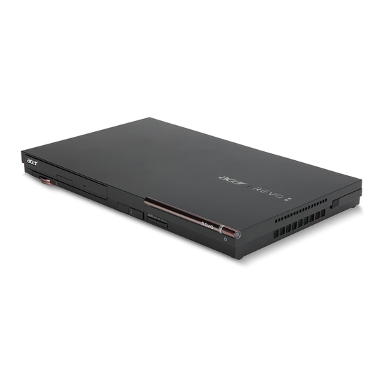
- Page 1 Acer Aspire RL100 Service Guide PRINTED IN TAIWAN...
-
Page 2: Revision History
Revision History Please refer to the table below for the updates made on this service guide. Date Chapter Updates... - Page 3 Copyright Copyright © 2010 by Acer Incorporated. All rights reserved. No part of this publication may be reproduced, transmitted, transcribed, stored in a retrieval system, or translated into any language or computer language, in any form or by any means, electronic, mechanical, magnetic, optical, chemical, manual or otherwise, without...
- Page 4 Any Acer Incorporated software described in this manual is sold or licensed "as is". Should the programs prove defective following their purchase, the buyer (and not Acer Incorporated, its distributor, or its dealer) assumes the entire cost of all necessary servicing, repair, and any incidental or consequential damages resulting from any defect in the software.
- Page 5 Conventions The following conventions are used in this manual: SCREEN MESSAGES NOTE WARNING CAUTION IMPORTANT Denotes actual messages that appear on screen. Gives additional information related to the current topic. Alerts you to any physical risk or system damage that might result from doing or not doing specific actions.
-
Page 6: Fru Information
Service Guide. For ACER-AUTHORIZED SERVICE PROVIDERS, your Acer office may have a DIFFERENT part number code to those given in the FRU list of this printed Service Guide. You MUST use the list provided by your regional Acer office to order FRU parts for repair and service of customer machines. -
Page 7: Table Of Contents
Table of Contents Chapter 1 - System Tour Features ............1 System Components . - Page 8 BIOS Flashing and Recovery ......... . .53 Undetermined Problems .
-
Page 9: Chapter 1 - System Tour
System Tour Features Below is a brief summary of the computer’s many features. NOTE: The features listed in this section is for your reference only. The exact configuration of the system depends on the model purchased. Processor One S1G4 socket ... -
Page 10: Operating System And Software
Windows 7 Home Premium X64 Windows 7 Embedded 32 bit Linux 2.6 or higher FreeDOS Applications Acer eRecovery Management Acrobat Reader Acrobat Flash Player Acer Revo Arcade McAfee Internet Security ... -
Page 11: System Components
System Components This section is a virtual tour of the system’s interior and exterior components. Front Panel Icon Chapter 1 Component Wireless touchpad eject button Volume wheel Wireless touchpad battery indicator* Wireless touchpad (mouse mode and keyboard mode) Optical disc drive USB RF 2.4 GHz receiver Media card reader (selected models only) Power button... -
Page 12: Rear Panel
Rear Panel Icon Component Power socket RJ-45 Ethernet connector HDMI port S/PDIF port Aerial connector (selected models only) Microphone/speaker-out/line-in jack Speaker or headphone jack USB port Chapter 1... -
Page 13: Internal Components
Internal Components Component Heatsink WLAN module Hard disk drive Optical drive System fan Chapter 1... -
Page 14: System Led Indicator
System LED Indicator This section describes the system LED indicator. LED indicator Color Wireless touchpad battery indicator — LED status Description Charging Flashing Battery level low — Battery is fully charged Chapter 1... -
Page 15: Chapter 2 - System Utilities
System Utilities CMOS Setup Utility CMOS setup is a hardware configuration program built into the system ROM, called the complementary metal- oxide semiconductor (CMOS) Setup Utility. Since most systems are already properly configured and optimized, there is no need to run this utility. You will need to run this utility under the following conditions. When changing the system configuration settings ... -
Page 16: Entering Cmos Setup
Entering CMOS setup Turn on the computer and the monitor. If the computer is already turned on, close all open applications, then restart the computer. During POST, press Delete. If you fail to press Delete before POST is completed, you will need to restart the computer. The Setup Main menu will be displayed showing the Setup’s menu bar. -
Page 17: Setup Utility Menus
Setup Utility Menus CMOS Setup Utility - Copyright (C) 1985-2010, American Megatrends, Inc. ► Product Information ► Standard CMOS Features ► Advanced BIOS Features ► Advanced Chipset Features ► Integrated Peripherals ► Power Management Setup :Move F1:General Help The Setup Main menu includes the following main setup categories. Product Information ... -
Page 18: Product Information
Product Information The Product Information menu displays basic information about the system. These entries are for your reference only and are not user-configurable. Processor Type AMD Athlon(TM) II Neo K325 Dual-Core Processor Processor Speed System Memory Product Name System Serial Number System BIOS Version BIOS Release Date Asset Tag Number... -
Page 19: Standard Cmos Features
Standard CMOS Features System Date System Time ► SATA Port 1 ► SATA Port 2 Halt On :Move F1:General Help Parameter Description System Date Set the date following the weekday-month-day-year format. System Time Set the system time following the hour-minute-second format. SATA Port 1/2 Displays the status of auto detection of the AHCI device. -
Page 20: Advanced Bios Features
Advanced BIOS Features Quick Boot Quiet Boot 1st Boot device 2nd Boot device 3rd Boot device 4th Boot device ► Hard Disk Drive Priority ► Optical Disk Drive Priority ► Removable Device Priority ► Network Device Priority Bootup Num-Lock Boot Sector Virus Protection :Move F1:General Help Parameter... - Page 21 Hard Disk Drive Priority This feature allows you to specify the boot sequence from all available hard disk drives. Hard Disk Drives 1st Drive :Move F1:General Help Optical Disk Drive Priority This feature allows you to specify the boot sequence from all available CD/VD drives. CD/DVD Drives 1st Drive :Move...
-
Page 22: Removable Device Priority
Removable Device Priority This feature allows you to specify the boot sequence from all available removable drives. Removable Drives 1st Drive :Move F1:General Help Network Device Priority This feature allows you to specify the boot sequence from all available network devices. Network Drives 1st Drive :Move... -
Page 23: Advanced Chipset Features
Advanced Chipset Features AMD Cool’n’Quiet AMD-V :Move F1:General Help Parameter Description AMD Cool’n’Quiet Enables or disables the AMD Cool’nQuiet Technology. AMD-V Enables or disables the AMD Virtualization Technology (VT) availability. Chapter 2 CMOS Setup Utility - Copyright (C) 1985-2010, American Megatrends, Inc. Advanced Chipset Features [Enabled] [Enabled]... -
Page 24: Integrated Peripherals
Integrated Peripherals Onboard SATA Controller Onboard SATA Mode Onboard USB Controller Legacy USB Support USB Storage Emulation Onboard Audio Controller Onboard LAN Controller Onboard LAN Option ROM :Move F1:General Help Parameter Description Onboard SATA Controller Enables or disables the onboard SATA controller. Onboard SATA Mode Select an operating mode for the onboard SATA. -
Page 25: Power Management Setup
Power Management Setup ACPI Suspend Mode Deep Power Off Mode Power On by RTC Alarm Power On by Onboard LAN Wake Up by USB KB/Mouse Restore On AC Power Loss :Move F1:General Help Parameter Description ACPI Suspend Mode Select an ACPI state used for System Suspend. Deep Power Off Mode Enables or disables the deep power off mode. -
Page 26: Pc Health Status
PC Health Status CPU Temperature System Temperature CPU Fan Speed CPU Core VGA Core Smart Fan :Move F1:General Help Parameter Description Smart Fan Enables or disables the smart system fan control function. CMOS Setup Utility - Copyright (C) 1985-2010, American Megatrends, Inc. PC Health Status :61 C/141 F :51 C/123 F... - Page 27 Frequency/Voltage Control Clock to All DIMM/PCI/PCIE Spread Spectrum :Move F1:General Help Parameter Description Clock to All DIMM/PCI/PCIE Enables or disables clock to all DIMMs, PCI, or PCIE. Spread Spectrum Enables or disables the reduction of the mainboard’s EMI. Note: Remember to disable the Spread Spectrum feature if you are overclocking.
-
Page 28: Bios Security Features
BIOS Security Features Supervisor Password :Not Installed User Password Change Supervisor Password Change User Password :Move F1:General Help Parameter Description Supervisor Password Indicates the status of the supervisor password. User Password Indicates the status of the user password. Change Supervisor Supervisor password prevents unauthorized access to the BIOS Setup Utility. - Page 29 Removing a system password Use the up/down arrow keys to select password parameter (Change Supervisor Password or Change User Password) menu then press Enter. Enter the current password then press Enter. Press Enter twice without entering anything in the password fields. Chapter 2...
-
Page 30: Load Default Settings
Load Default Settings The Load Default Settings menu allows you to load the default settings for all BIOS setup parameters. Setup defaults are quite demanding in terms of resources consumption. If you are using low-speed memory chips or other kinds of low-performance components and you choose to load these settings, the system might not function properly. - Page 31 Save & Exit Setup The Save & Exit Setup menu allows you to save changes made and close the Setup Utility. ► Product Information ► Standard CMOS Features ► Advanced BIOS Features ► Advanced Chipset Features ► Integrated Peripherals ► Power Management Setup :Move F1:General Help Chapter 2...
-
Page 32: Exit Without Saving
Exit Without Saving The Exit Without Saving menu allows you to discard changes made and close the Setup Utility. ► Product Information ► Standard CMOS Features ► Advanced BIOS Features ► Advanced Chipset Features ► Integrated Peripherals ► Power Management Setup :Move F1:General Help CMOS Setup Utility - Copyright (C) 1985-2010, American Megatrends, Inc. -
Page 33: Updating The Bios
Updating the BIOS The BIOS flash update is required for the following conditions: New versions of system programs New features or options Restore a BIOS when it becomes corrupted NOTE: Observe the following when using the Flash utility to update the system BIOS flash ROM. - To perform a Windows-based BIOS flash, you should find the Flash utility on the system drive. - Page 34 Chapter 2...
-
Page 35: Disassembly Requirements
System Disassembly This chapter contains step-by-step procedures on how to disassemble the desktop computer for maintenance and troubleshooting. Disassembly Requirements To disassemble the computer, you need the following tools: Wrist grounding strap and conductive mat for preventing electrostatic discharge Flat-blade screwdriver ... -
Page 36: Pre-Disassembly Procedure
Pre-disassembly Procedure Before proceeding with the disassembly procedure, perform the steps listed below: Turn off the system and all the peripherals connected to it. Unplug the AC adapter and all power and signal cables from the system. Unplug all peripheral cables from the system. Place the system unit on a flat, stable surface. -
Page 37: External Module Disassembly
External Module Disassembly Removing the USB RF Receiver Pull the USB RF receiver out of the port. Removing the Card Reader Dummy Card Push against the card, as if you were pushing it further into the slot, letting the card spring out. Remove the card from the slot. -
Page 38: Removing The Wireless Touchpad
Removing the Wireless Touchpad Slide the wireless touchpad eject button to eject the wireless touchpad. Pull the wireless touchpad out of the bay. Removing the Dummy Stand Slide the dummy stand off the slot. Chapter 3... -
Page 39: Main Unit Disassembly
Main Unit Disassembly The flowchart illustrate the entire disassembly sequence. Observe the order of the sequence to avoid damage to any of the hardware components. Chapter 3... -
Page 40: Removing The Top Cover
Screw List Code MECH TRUSS M3*L4 NI Removing the Top Cover Perform the pre-disassembly procedure described on page 28. Remove the four screws (A) securing the top cover. Screw (Quantity) M3L4 HEX FLAT (4) Pry loose the top cover from the lower cover and remove the top cover. Screw M3L4 HEX FLAT M2*2... -
Page 41: Removing The Optical Drive
Removing the Optical Drive Remove the top cover. Refer to the previous section for instructions. Remove the two screws (B) securing the optical drive. Screw (Quantity) MECH TRUSS M3*L4 NI (2) Remove the screw (C) that holds the bracket to the optical drive and system. Screw (Quantity) M2*2 (1) Chapter 3... - Page 42 Lift the optical drive off the mainboard and remove the bracket. Remove the screws (C) securing the two brackets to the optical drive. Screw (Quantity) M2*2 (3) Remove the brackets. Color Torque 1.5 0.2 kgf-cm Silver Part No. 86.9AJ32.2R0 Chapter 3...
-
Page 43: Removing The Heatsink
Remove the optical drive cover. Removing the Heatsink WARNING:The heatsink becomes very hot when the system is on. NEVER touch the heatsink with any metal or with your hands. See “Removing the Top Cover” on page 32. Use a long-nosed screwdriver to loosen the four screws on the heatsink. Lift the heatsink off the mainboard. -
Page 44: Removing The Fan
Lay it down in an upright position—with the thermal patch facing upward. Do not let the thermal patch on the heatsink touch the work surface. Use an alcohol pad to wipe off the thermal grease from both the heatsink and the processor. Removing the Fan WARNING:The fan becomes very hot when the system is on. -
Page 45: Removing The Wlan Module
Remove the fan from the mainboard. Removing the WLAN Module See “Removing the Top Cover” on page 32. Disconnect the black antenna from the main connector and the white antenna from the auxiliary connector on the WLAN module. Remove the screw (D) securing the WLAN module. Screw (Quantity) M2 CAP L4 NI (1) Chapter 3... -
Page 46: Removing The I/O Board
Detach the module out of the slot. NOTE: When attaching the antennas back to the WLAN module, make sure the cables are arranged properly. Removing the I/O Board See “Removing the Top Cover” on page 32. Peel the tape off the I/O board and move the antenna cables away from the board. Open the I/O board cable connector and disconnect the cable. -
Page 47: Removing The Mainboard
Remove the two screws (B) securing the I/O board. Screw (Quantity) MECH TRUSS M3*L4 NI (2) NOTE: The I/O board has been highlighted with a yellow rectangle as above image shows. Please detach the board and follow local regulations for disposal. Detach the I/O board. -
Page 48: Removing The Memory Module
Remove the three screws (B) securing the mainboard. Screw (Quantity) MECH TRUSS M3*L4 NI (3) NOTE: The mainboard has been highlighted with a yellow rectangle as above image shows. Please detach the mainboard and follow local regulations for disposal. Lift the board off the base cover. Removing the Memory Module IMPORTANT:Before removing any DIMM, make sure to create a backup file of all important data. -
Page 49: Removing The Tv Tuner Card
Push out the latches on both sides of the DIMM socket to release the DIMM. Remove the DIMM module. NOTE: The DIMM has been highlighted with a yellow rectangle as above image shows. Please detach the DIMM and follow local regulations for disposal. Removing the TV Tuner Card See “Removing the Mainboard”... -
Page 50: Removing The Battery
Remove the screw (D) securing the TV tuner card. Screw (Quantity) SCRW M2 CAP L4 NI (1) Detach the card out of the slot. Removing the Battery See “Removing the Mainboard” on page 39. Detach the battery cable. Color Torque 4.5 ... -
Page 51: Removing The Hard Disk Drive
Remove the battery. NOTE: The battery has been highlighted with a yellow circle in the previous image. Detach the battery and follow the local regulations for disposing it. Removing the Hard Disk Drive See “Removing the Mainboard” on page 39. Remove the four screws (B) securing the hard disk drive module. - Page 52 Detach the hard disk drive from its connector and lift it off the mainboard. Chapter 3...
-
Page 53: Hardware Diagnostic Procedure
This chapter provides instructions on how to troubleshoot system hardware problems. Hardware Diagnostic Procedure IMPORTANT:The diagnostic tests described in this chapter are only intended to test Acer products. Non-Acer products, prototype cards, or modified options can give false errors and invalid system responses. -
Page 54: System Check Procedures
Verify that components are properly seated. Verify that all cable connectors inside the system are firmly and correctly attached to their appropriate connectors. Verify that all components are Acer-qualified and supported. 10. Replace the system covers. 11. Power on the system. -
Page 55: Checkpoints
Checkpoints A checkpoint is either a byte or word value output to I/O port 80h. The BIOS outputs checkpoints throughout bootblock and Power-On Self Test (POST) to indicate the task the system is currently executing. Checkpoints are very useful in aiding software developers or technicians in debugging problems that occur during the pre- boot process. -
Page 56: Bootblock Recovery Code Checkpoints
Bootblock Recovery Code Checkpoints The Bootblock recovery code gets control when the BIOS determines that a BIOS recovery needs to occur because the user has forced the update or the BIOS checksum is corrupt. The following table describes the type of checkpoints that may occur during the Bootblock recovery portion of the BIOS. NOTE: Checkpoints may differ between different platforms based on system configuration. -
Page 57: Post Code Checkpoints
POST Code Checkpoints The POST code checkpoints are the largest set of checkpoints during the BIOS preboot process. The following table describes the type of checkpoints that may occur during the POST portion of the BIOS. NOTE: Please note that checkpoints may differ between different platforms based on system configuration. Checkpoints may change due to vendor requirements, system chipset or option ROMs from add-in PCI devices. - Page 58 Checkpoint Initialize RTC date/time. Test for total memory installed in the system. Also, Check for DEL or ESC keys to limit memory test. Display total memory in the system. Mid POST initialization of chipset registers. Detect different devices (Parallel ports, serial ports, and coprocessor in CPU, ... etc.) successfully installed in the system and update the BDA, EBDA…etc.
-
Page 59: Dim Code Checkpoints
DIM Code Checkpoints The Device Initialization Manager (DIM) gets control at various times during BIOS POST to initialize different system busses. The following table describes the main checkpoints where the DIM module is accessed. NOTE: Checkpoints may differ between different platforms based on system configuration. Checkpoints may change due to vendor requirements, system chipset or option ROMs from add-in PCI devices. -
Page 60: Beep Codes
Beep Codes Beep codes are used by the BIOS to indicate a serious or fatal error to the end user. Beep codes are used when an error occurs before the system video has been initialized. Beep codes will be generated by the system board speaker, commonly referred to as the PC speaker. -
Page 61: Bios Flashing And Recovery
BIOS Flashing and Recovery This section includes two ways to recover the BIOS, using a Windows-based Flash utility or DOS-based Flash utility. Windows-based BIOS recovery Locate the WinFlash utility on the computer’s local disk. (1). Open Local Disk C on the computer. (2). - Page 62 After the BIOS update is completed, the “Program ended normally “ message displays. Restart the system. As soon as the POST starts, press Delete to enter the Setup Utility. Select Load Default Settings, then press Enter. Select Ok, then press Enter. 10.
- Page 63 DOS-based BIOS Recovery Create a bootable USB storage device. (1). Connect the USB storage device to a USB port on the computer. (2). Copy the DOS Flash utility to the USB storage device. The utility should contain the “AFUDOS.exe”, “Flash.bat”, and “Flash.ROM” files. (3).
- Page 64 11. After the BIOS update is completed, the “Program ended normally “ message displays. 12. Restart the system. 13. As soon as the POST starts, press Delete to enter the Setup Utility. 14. Select Load Default Settings, then press Enter. 15.
-
Page 65: Undetermined Problems
Follow procedures below to isolate the failing FRU. Do not isolate non-defective FRU. Power off the computer. Visually check them for damage. If any problems are found, replace the FRU. Remove or disconnect all of the following devices: Non-Acer devices Printer, mouse, and other external devices ... - Page 66 Chapter 4...
-
Page 67: System Block Diagram
Chapter 5 System Block Diagram and Board Layout System Block Diagram Chapter 5... -
Page 68: Mainboard Layout
Mainboard Layout Top view Code SKT4 SKT6 SKT3 SKT1 and SKT2 CPUFAN1 Description Aerial connector S/PDIF connector HDMI connector LAN connector Power adapter connector WLAN module connector N11M-PT1 AMD ASB2 CPU 2.5” HDD connector BIOS SPI ROM USB ports NForce MCP61 I/O board cable connector CPU fan power connector Chapter 5... -
Page 69: Bottom View
Bottom view Code 2, 3 CN2 and CN6 SKT5 Chapter 5 Description SD card connector SoDIMM slot TV tuner card connector... - Page 70 Chapter 5...
-
Page 71: Chapter 6 - Fru (Field Replaceable Unit) List
To scrap or to return the defective parts, follow the local government ordinance or regulations on how to dispose it properly, or follow the rules set by your regional Acer office on how to return it. This document will be updated as more information about the FRU list becomes available. -
Page 72: Exploded Diagram
Exploded Diagram Chapter 6... - Page 73 Chapter 6 Part Name Nut insert M3L3 Top cover Top deco lens Top deco 2 Power button Top cover deco Bottom case assembly Bottom mesh Bottom cover Rubber foot USB cover ODD logo ODD cover ODD button Keyboard latch cap Keyboard latch spring Keyboard latch Rear base...
-
Page 74: Fru List
HLDS Super-Multi DRIVE 12.7mm Tray DL 8X GT31N (R5-1) LF W/O bezel SATA GT31N PLDS Super-Multi DRIVE 12.7mm Tray DL 8X DS-8A5SH LF+HF W/ O bezel SATA DS-8A5SH NVIDIA IC VGA N11M-PT1-S-B1 BGA 533P WLAN Part Name Acer Part No. MB.SES01.001 23.10427.001 23.10428.001 60.3CQ01.001 KC.AKB02.325 KN.1GB07.004 KN.2GB07.004... - Page 75 Lite-On WN6602RH, Ralink RT3090, Half-size 802.11 b/g/n (mini- card)(half size) TV TUNER CARD AverMedia A336-D Mini-Card WW Analog + DVB-T Digital AverMedia A336-A Mini-Card WW Analog + ATSC Digital POWER CORD Power cord Chapter 6 NI.10200.034 TU.10500.052 TU.10500.051 27.01518.A11...
- Page 76 Chapter 6...
-
Page 77: Appendix A - Technical Specifications
Technical Specifications This section provides technical specifications for the system. Processor AMD Athlon™ II Neo Dual-Core Item Model number Frequency (MHz) System Bus Speed (MHz) Wattage L2 Cache Size Socket Process Technology System Board Major Chips Item Specification System core logic AMD processor + nVIDIA MCP61D Video controller nVidia N11M-PT1... - Page 78 System BIOS Item Specification BIOS vendor American Megatrends Inc. BIOS version P0611-D04 Hard Disk Drive Item Specification Vendor Model no. WD1600BEVT-22A23T0 WD2500BEVT-22A23T0 WD3200BEVT-22A23T0 WD5000BEVT-22A0RT0 Capacity (GB) 160, 250, 320, 500 Interface SATA 3 Gb/s Size 2.5-inch Transfer rate (Gb/s) Spindle speed (RPM) 5400 Cache (MB) Video Interface...
- Page 79 Input Devices Item Controller Connectors Optical Drive BD Combo Module Item Vendor Model name Drive type Write Speed Read Speed Appendix A Specification SIO ITE 8755/ITE8758 Four USB ports (two on front and two on rear) Specification HLDS PLDS CT21N DS-8A5SH BD-Combo BD-Combo...
- Page 80 BD Combo Module Item Data Transfer Rate Access Time Buffer Size Interface Type Super Multi Item Vendor Model Name Drive Type Write Speed Read Speed Data Transfer Rate Access Time Buffer Size Interface Type Specification BD-ROM 35.965 Mbits/s DVD-ROM 1.85Mbytes/s CD-ROM 150KB/s BD-ROM: 200 ms typ CD: 130 - 250 ms typ...