Buffalo AirStation WBR2-G54 User Manual
Wireless cable/dsl router-g
Hide thumbs
Also See for AirStation WBR2-G54:
- Quick setup manual (10 pages) ,
- Brochure & specs (2 pages) ,
- Specification sheet (2 pages)
Table of Contents
Advertisement
Quick Links
Advertisement
Table of Contents

Related Manuals for Buffalo AirStation WBR2-G54


Summary of Contents for Buffalo AirStation WBR2-G54
-
Page 1: User Manual
User Manual Wireless Cable/DSL Router-G WBR2-G54 www.buffalotech.com/wireless... -
Page 2: Table Of Contents
Introduction ......05 Installation / Setup ..... . 11 Antenna Installation. - Page 3 Network Settings..... 45 Routing Setup ....45 Address Translation .
- Page 4 Table of Contents Specifications ......71 Troubleshooting ......76 Glossary .
-
Page 5: Introduction
This manual, which describes the most common configurations, introduces you to the AirStation Cable/DSL Router, and will help you connect to your network quickly. The WBR2-G54 router, is a wireless 4-port router small/medium business (SMB) network device that complies with the 2.4GHz IEEE 802.11g standard specification on wireless LANs. The WBR2- G54 supports enhanced built-in NAT/SPI firewall functions and is used as a multi-functional router/... -
Page 6: Airstation Wireless Network Features
• SOHO/SMB routing and firewall functions provide a safer private networking environment, includ- ing support for MS NetMeeting and MSN-Messenger. • Additional SPI Firewall Functions - DMZ, intrusion detection and notification • Syslog transmits some or all system activities to a central Syslog server. •... -
Page 7: Home Networking
- Packet monitoring and filtering by MAC address, IP address and port. - PPPoE support - WDS support • Buffalo’s easy web interface configuration • Broadband router static and dynamic routing methods between WAN and LAN based on updated routing tables. An economical way to bridge multiple networks. •... - Page 8 Introduction neously. Buffalo AirStation wireless access points enable sharing broadband by simply connecting the AirStation to a DSL or CATV modem to: • Share files and printers • Access and share the Internet • Share media files SOHO/SMB Networking With high-speed DSL or CATV connections readily available, many users can work effectively from a home office, connected securely to a corporate network.
-
Page 9: System Requirements
The LAN or Wired MAC address is the default ESS-ID (SSID) of the AirStation. The LAN MAC address is clearly labeled on the back of the AirStation. offi ce. Connect the Buffalo AirStation Broadband router AP to a CATV or DSL modem in order to: •Share broadband access •Share fi... -
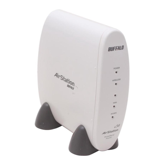
Page 10: Product Views
• Any Wi-Fi (wireless) compatible computer with a Web Browser Internet Explorer or Netscape 4.5 or later. (Safari 1.0 is supported with Macintosh OS X.2) AirStation WBR2-G54 Package Contents The AirStation WBR2-G54 package consists of the following items. 1. WBR2-G54 Base Station 2. AC adapter and power cable 3. -
Page 11: Installation / Setup
If you do not agree to all of the terms of the Software Li- cense Agreement, do not download, copy or install the AirStation software. It is the policy of Buffalo Technology to improve... - Page 12 you to combine and share wired and wireless computers and printers with the high-speed internet connection. 1. Power down the cable or DSL modem and the computer which will be used to configure the AirStation router. 2. Plug the cable or DSL’s LAN Ethernet cable into the AirStation’s WAN port. Initially, you may need to unplug this cable from your computer, hub or other router.
-
Page 13: Antenna Installation
To install the antenna, slide the antenna connector door on the back of the WBR2-G54 to the right. This will expose the MC Connector. Attaching the antenna is simple, just insert the antenna’s MC Connector into the WBR2-G54’s MC Con- nector and firmly push it in until it snaps into place. -
Page 14: Standard Settings
Introduction Confi guring the AirStation using a standard web browser requires basic wireless confi guration knowledge. Setup includes manual wireless confi guration and basic administrative management. Setup Preparation Setup Preparation Initial Settings Login will eliminate possible setup problems due to any issues with the wireless adapter on the computer being used to confi... -
Page 15: Open The Setup Screen
Open the Setup Screen • Connect the WBR2-G54 according to the wiring instructions in Section 2. • The WBR2-G54 has a default LAN IP address of 192.168.11.1 and Subnet Mask of 255.255.255.0. ■ Note: The computer used to configure the AirStation should be set to obtain an IP address automatically using a DHCP server. -
Page 16: Enter Isp Information
Initial Settings Screen Initial DSL button Screen Standard Settings Enter ISP information • Click the appropriate button to select the type of broadband access. (Users more experienced in networking may choose to select the Ad- vanced button and skip to Section 4.) •... - Page 17 Manual DSL IP Settings Screen DSL PPPoE Settings Screen Standard Settings Enter IP Address Manually - Enter the IP Address given by the ISP. - Use ‘Enter IP Address Manually’ if the ISP requires use of a static IP address. PPPoE Connection - Enter the PPPoE information provided by the ISP.
- Page 18 Initial CATV Settings Screen Manual IP Address Settings Standard Settings CATV (Cable) Button Select the appropriate connection method. Automatic IP Assignment by ISP - Select ‘Automatic IP Assignment by ISP’ if your ISP’s DHCP server assigns an IP address automatically. Enter IP Address Manually - Select ‘Enter IP Address Manually’...
- Page 19 Auto IP/ Manual DNS Settings Line Test Tab Standard Settings The IP Address is Acquired Au to mat i cal ly but DNS Server Address is Entered Manually - Select ‘IP address is acquired automatically but DNS server address is entered manually’ if the ISP’s DHCP server supplies an IP address but not DNS server addresses.
- Page 20 Standard Settings Security Security Tab The Security Tab offers three Simple Security Settings. Follow the in struc tions in each screen to enter WEP keys, MAC Address Filtering and the degree of fi rewall security for the AirStation.
- Page 21 Simple WEP Setup. - Select the desired encryption and enter an appropriate WEP key to encrypt your network. See the section on Wireless LAN Security starting on ‘Page 22’ for more information on encryption. Simple MAC Address Filter. - Select ‘Limit’ to use MAC fi lter- ing.
- Page 22 Ap pli ca tion Ap pli ca tion Standard Settings Applications The Application Tab offers setup for special ap- plications such as games, MS NetMeeting and MSN Messenger. Then follow the on-screen menus to confi gure the AirStation for the applica- tion.
- Page 23 Web Gaming Setup -Enter the ports(refer to Game documentation) the game runs on, and enter the Local IP Ad- dress of the PC that plays the game. Although your AirStation will function fi ne using only the Standard Settings, you may wish to explore more advanced options.
-
Page 24: Aoss Setup
Configure your WBR2-G54's internet con- ◗ nection by referring to the instructions in the WBR2-G54's Quick Setup Guide. Once the WBR2-G54 has been config- ◗ ured, follow the directions to install your wireless client device and its drivers if necessary. Certain wireless client adapt- ers require client software to configure... - Page 25 To begin the configuration, press the AOSS button on ◗ the back of the WBR2-G54 for 3-5 seconds. The AOSS light will begin to flash when the AOSS mode has been enabled. You can stop pressing the button at this point.
- Page 26 Additional AOSS Information: Only one AOSS wireless client adapter can be configured to the AOSS router at a time. Thus, ◗ the button will need to be repressed for each additional AOSS wireless client adapter that will be connected. It is not necessary to AOSS client devices that have already been configured via AOSS, unless ◗...
-
Page 27: Advanced Setup
LAN Settings Wireless Settings up to 32 al pha nu mer ic characters for the ESS-ID (case sensitive). By default the ESS-ID is the LAN Mac address of the AirStation. ■ Note: Roaming - When multiple AirStations have an identical ESS-ID, WEP key (if WEP is used), (and channel in WDS mode) , client computers may Roam between the AirStations. -
Page 28: Advanced Settings
ping channels. Channels 1, 6 and 11 are non-overlapping. If there are multiple APs in close proximity using the same channel, there may be interference. In this case, change to a non-overlapping channel. Privacy Separator - Enable or disable communication between wireless clients. If you choose to use this feature, every wireless client that is associated to the AirStation will not be able to commu- nicate with any other wireless clients. -
Page 29: Wireless Lan Security
may delay wireless communication. The default value of 1 is recommended. Wireless output power - Confi gure output power of the AirStation. Decrease wireless output power to shrink the wireless communication range. The default setting of 100% is recommended unless decreased range is desired Wireless LAN Security Broadcast SSID - Enable or Disable the SSID (ESS-ID) from being broadcasted. - Page 30 Advanced Settings cryption key should be entered. - TKIP - Uses TKIP (Temporal Key Integrity Protocol) for data encryption. The encryption key is renewed every “Re-key interval” when “TKIP” is selected. WEP - When the WEP (Wired Equivalent Protection) encryption standard is implemented into a wireless network, a WEP key is used between the client and access point to successfully encrypt, transmit and decrypt data.
- Page 31 Advanced Settings Characteristics: - The Initialization Vector is expanded from 24-bits to 48-bits. - The Initialization Vector is randomized. - Uses a different RC4 key for every packet. TIKIP requires an 8 to 63 character passphrase in ASCII or 64 digits hexadecimal key. Example 1: [ airstation -WPA-PSK ] Example 2: [0123456789abcdef0123456789abcdef0123456789abcdef0123456789abcdef] WPA Group Rekey Interval - When TKIP is selected, the encryption key is renewed at this inter-...
-
Page 32: Lan Port
LAN Port LAN Port Settings Settings the IP address is changed, then the DHCP scope must be changed to match. DHCP Server Function - Allows administrator to enable/disable the DHCP server function for the AirStation LAN side. Select Use to enable and Do not use to disable the function. Once Use is selected, the assigned IP address range can be specifi... -
Page 33: Dhcp Server
DHCP Server DHCP Server Settings Settings server is turned off, all client PC’s must have unique, static IP addresses and valid network settings manually entered. Check with your LAN administrator for static IP information. Assigned IP address (Range As sign ment) - Sets the beginning address and range of addresses to be assigned by the AirStation’s DHCP server function. - Page 34 Advanced Settings Lease duration - Specifies the time in hours (1-999) an assigned IP address is valid. If the client computer does not request a renewal of IP address before the lease period expires, the AirStation can issue the IP to another client computer. Default Gateway - Allows administrator to use the Default Gateway address (the AirStation’s IP address), assign a specific Gateway address, or block clients from Gateway notification.
- Page 35 Advanced Settings Manual IP Manual IP and MAC Address and MAC As sign ment - Allows adminis- Address trator to add additional leased Assignment IP addresses tied to a specifi c Settings MAC address. When a spe- cifi c MAC address connects to the AP, the IP address speci- fi...
-
Page 36: Wireless Mac Filtering
Advanced Settings Wireless MAC Filter Wireless MAC Filter Wireless PC’s Connection - Select Enable to restrict wireless connections to the registered adapters in the list. Select Disable to disable MAC address fi ltering. Press the Preset button to enter the MAC Address registration menus. - Page 37 Advanced Settings Registration for MAC Ad- Register for Allowable PC’s dresses - MAC access MAC Address restriction set up in LAN. Input the MAC addresses that are allowed to communicate with the AirStation. MAC address list - Displays a table list of all MAC addresses allowed to communicate with the AirStation.
-
Page 38: Wireless Bridge (Wds)
Wireless Bridge (WDS) Settings ■ Note: All AirStations must support WDS and be on the same channel. For roaming support, use the same SSID on all devices. Add AirStation (wireless MAC Address): Allows administrator to input the wireless MAC address of AirStations for Bridge (WDS) communication. - Page 39 Wireless Bridge (WDS) Settings Repeat this process on every other AirStation used in Bridge (WDS) mode. Advanced Settings To enable WDS, set the Wire- less Bridge (WDS) function to Enable. Enter the Wireless MAC address of the AirStation to communicate with in the form of two characters separated by a colon and click Add.
-
Page 40: Wan Settings
WAN port WAN port Setup Setup ministrator to select DHCP server, PPPoE, or manual setting for the WAN port of the AirStation. ministrator to select DHCP server, PPPoE, or manual setting for the WAN port of the AirStation. Auto IP assignment from DHCP server - acquire the IP address automatically from the DHCP server. Use PPPoE client - If selected, the in for ma tion listed below must be entered. - Page 41 Advanced Settings PPPoE Setting (for enabling PPPoE Client function) - Allows administrator to use PPPoE as specified by the ISP. The following parameters should be entered for PPPoE Settings: Name of Connection - Enter the name of your connection. User Name - Enter the user name (up to 64 alphanumeric characters) for PPPoE authorization. Password - Enter the password provided by your ISP (up to 64 alphanumeric characters).
- Page 42 PPPoE Settings Screen once per minute. If there is no reply within six minutes, the client disconnects. Set to Disable if frequent disconnection occurs. Activation - Enable/disable registered connection settings. If disabled, the connection is not per- mitted. Advanced Settings Authorization - Authorization method for accessing the ISP’s PPPoE server.
-
Page 43: Wan Network
Network of Network of as sign ment from DHCP Server is selected in the WAN Port section, a gateway IP is assigned automatically, provided the DHCP server is set to provide one. DNS Server Address - Enter the primary and secondary DNS address(es) of the server to be used by the AirStation for DNS resolution. - Page 44 Advanced Settings Port Number for WEB Settings - Set a specific port number when remote setup of the AirStation is planned. Using port 80 allows the AirStation to be accessed from the internet by connecting to http://xxx.xxx.xxx.xxx (where xxx.xxx.xxx.xxx is your WAN IP address). You will need to configure the NAT (Adress Translation Settings) to forward PORT 80 back to the AirStation.
-
Page 45: Network Settings
Routing Setup RIP transmission to WAN - Allows RIP transmission or None (no RIP) to WAN Display current information - Allows administrator to view and delete routing information. Click Add Route to Add a Routing Table Entry •Destination address - Network IP address and subnet mask. Advanced Settings Network Settings Routing Setup... - Page 46 Advanced Settings Add Routing • Gateway - Address through Table Entry which the packet passes be- fore it reaches the des ti na tion address. • Metric - Number of routers (1-15) to be passed before the packet reaches its destination.
-
Page 47: Address Translation
Address Address Translation Translation Setup Setup • Static IP address translation -When the WAN requests connection to the LAN, the WAN IP address of the AirStation is translated into the IP address of the LAN computer. Log Output - Set ‘Log Output’ to log discarded packets. Otherwise, a dropped packed is not logged. - Page 48 IP address of DMZ - Allows administrator to set the DMZ (De-Militarized Zone) address. Incoming packets containing no recognizable destination port information will be re di rect ed to the DMZ’s IP address. Display/Delete NAT Table - Allows ad min is tra tor to delete NAT tables. Add NAT Table Group - Specify a group (up to 16 characters) that the NAT rule belongs.
- Page 49 Advanced Settings Some network applications (online games or streaming software) require adding Address Transla- tion tables; consult the software’s documentation for port information). Protocol (WAN): • All - Selects all IP protocols. • ICMP - Network Diagnostic Protocol (1). • Manual - Specify the protocol number (0-65535). •...
-
Page 50: Packet Filter
Packet Packet Filter Filter Setup Setup • Prohibit setup via wireless bridge access point - Prohibits a personal computer connected to another AirStation in a wireless bridge. • Prohibit NBT and Microsoft-DS routing - Prevent unexpected external access via Microsoft network sharing. - Page 51 Basic Filter Basic Filter Setting Setting Advanced Settings Use this fi lter when the commu- Use this fi lter when the commu- nication speed goes down using nication speed goes down using a network application like E-mail, a network application like E-mail, FTP and WEB.
-
Page 52: Ip Filter Setting
IP Filter IP Filter setting setting • WAN side - packets coming from the WAN side will be fi ltered. • WAN side - packets coming from the WAN side will be fi ltered. • LAN side - packets from the LAN side will be fi ltered. Are : •... - Page 53 no longer have access to the AirStation confi guration screens. This function prohibits setup from a wireless or wired computer. The AirStation can be returned to the factory default settings by holding down the INIT button on the back of the unit for fi ve seconds or until the red DIAG light becomes solid.
- Page 54 Advanced Settings ■ Note: If configuring from a wireless computer, add your MAC address to the list of authorized wireless LAN PCs. The MAC address must be in two-digit groups separated by colons. Example: 00:40:26:00:11:22 Click Apply when settings are complete.
-
Page 55: Intrusion Detector
Intrusion Detector Setup • Notifi cation email address - Enter des ti na tion email address • Sender email address - Enter the email address that will send the email. This is the name that will appear as the sender when the email is read. This email can be made up (e.g. DETECTOR@AIRSTATION Advanced Settings Intrusion Detector... - Page 56 • Sender email server address - Enter the SMTP Server address. • Receiving email server authorization - Enter the POP3 Server address, User name and Password. This is only required if your SMTP server requires POP verification before it allows email to be sent. Consult your ISP or mail server support for more information.
-
Page 57: Upnp
Advanced Settings UPnP UPnP Setting Select Use to enable UPnP (Universal Plug and Play). When a computer with UPnP support connects to the AirSta- tion, that computer automati- cally receives confi guration information from the AirStation. -
Page 58: Management
System Information with other access points. This is the best place to determine the wireless MAC address. • LAN Displays the AirStation LAN settings • WAN Displays the AirStation WAN settings • Default Gateway Displays the default gateway settings Advanced Settings Management System Information System information of the... -
Page 59: Change Password
• WAN side IP address auto acquisition WAN (Internet) side DHCP server. Press Release to release current DHCP WAN information. Press Renew to obtain WAN information from the DHCP server. NOTE: If a manual IP is assigned to the WAN port, this feature is not displayed. Name and Name and Password... -
Page 60: Time Setup
• New Password - Enter new password. Enter up to eight alphanumeric characters (case sensi- tive) • Confi rm Password - Reenter the new password for confi rmation Time Setup Screen Advanced Settings Time setup Time setup - Enter the current date and time, and click Set. -
Page 61: Traffic Information
Advanced Settings Packet Traffi c Packet Traf- Information fi c Informa- tion Displays number of packets sent and received for: Wired WAN Wired LAN Wireless LAN Click Refresh to start update the transfer packet log. -
Page 62: Client Monitor
Client Client Monitor Monitor Screen Screen Clients that have static IP addresses will not appear in the Client Monitor. Advanced Settings Client Monitor Displays the wired and wireless clients (computers) that are accessing the AirStation. • MAC address - Shows the client’s MAC address. -
Page 63: Ping Tool
PING Test Performs a PING test from the AirStation to a LAN or WAN address. PING Test PING Test Advanced Settings Enter the target IP address and click OK (e.g. 192.168.11.2 - OR- www.buffalotech.com) If the test results in an error, then verify you correctly inputted the address and check your connections. -
Page 64: Log Information
Advanced Settings Log Information Information Display log info level - Select Screen Error and/or Notify to spec- ify the types of reports to be logged by the AirStation. Display log info - Select the specifi c reports to be logged. Log information - Displays recorded logs. -
Page 65: Syslog Transfer
Advanced Settings Syslog Transfer Syslog Transmitting Screen Select Use or Do not use to enable or disable the AirStation’s ability to transmit information to a Syslog server. • Syslog Server - Enter the IP address of the Syslog server. • Log Information Level - Select Error and/or Notice to specify the types of reports to be sent to the Syslog server. -
Page 66: Save/Restore Settings
Save/ Save/ Restore Restore Settings Settings Screen Screen Advanced Settings Save/Restore Settings Save current settings - Click Save to open the fi le saving dialog and save the current AirStation settings to a fi le. Restored saved settings - Restores settings from a fi le that has been saved. -
Page 67: Reboot/Reload Settings
Advanced Settings Reboot/Reload Defaults Initialization/ Reboot Click Restart to reboot AirStation Click Restore to reset the AirStation to default factory settings. ■ Note: Resetting to default factory settings will erase all settings and passwords previously entered. The AirStation will return to the condition it was in when fi... -
Page 68: Firmware Updates
Firmware Firmware Update Update Advanced Settings Firmware Update Firmware fi le name - Click Browse to browse to the path and fi lename for the new fi rmware. Click Firmware Update to load fi rmware to the AirStation. ■ Note: Firmware update does not erase current user settings. -
Page 69: Aoss
Advanced Settings AOSS AOSS Client Table - Displays the clients connected via AOSS. The ‘Disconnect’ button disconnects the client from the AOSS router by using MAC Address filtering. Once disconnected, the client will still appear in the client list but will appear as disconnected. - Page 70 AOSS AOSS Start AOSS Process- Click AOSS icon to begin the AOSS sequence. This starts the AOSS process just like pressing the AOSS button. Stop AOSS Process- Click AOSS icon to stop AOSS operation. Stopping the AOSS function will turn off AOSS and return the router to non-AOSS function.
-
Page 71: Specifications
For more information, please consult: • The AirStation website at: http://www.buffalotech.com - for frequently asked questions (FAQ’s) and Software Updates. WBR2-G54 BASE STATION SPECIFICATIONS Physical Specifications Dimensions W3 x H6.75 x D6.1in. (76 x 171 x 155mm) Weight 1 lb. (620g) Temperature &... -
Page 72: Regulatory Information
Specifications Regulatory Information Wireless communication is often subject to local radio regulations. Although AirStation wireless networking products have been designed for operation in the license-free 2.4 GHz band, local radio regulations may impose limitations on the use of wireless communication equipment. Networking Characteristics Compatibility •... - Page 73 Modulation Technique Direct Sequence Spread Spectrum • ODFM for High Transmit Rate • DQPSK for Standard Transmit Rate • DBPSK for Low Transmit Rate Spreading 11-chip Barker Sequence Nominal Output Power 13.5 dBm Transmit Rate / Range High Speed 54 Mbps Medium Speed 36 Mbps Standard Speed 2 Mbps Low Speed 1 Mbps...
- Page 74 Specifications 400 m (1300 ft.) 550 m (1750 ft.) Semi-Open Office Environment 50 m (165 ft.) 70 m (230 ft.) 90 m (300 ft.) 115 m (375 ft.) Closed Office 25 m (80 ft.) 35 m (115 ft.) 40 m (130 ft.) 50 m (165 ft.) Receiver Sensitivity -83 dBm -87 dBm -91 dBm -94 dBm (depends on data rate) Delay Spread (at FER of <1%) 65 ns 225 ns 400 ns 500 ns (depends on data rate)
- Page 75 ■ Note: The range values listed in Table “Radio Characteristics” are typical distances as measured at Buffalo Technology AirStation laboratories. These values are provided for your guidance but may vary according to the actual radio conditions at the location where the AirStation product is installed.
-
Page 76: Troubleshooting
Common Problems: • Out of range, client cannot connect to the AirStation. • Configuration mismatch, client cannot connect to the AirStation. • Absence or conflict with the Client Driver. • Conflict of another device with the AirStation hardware. B.1.1 LED Activity B Monitoring LED activity helps identify problems. - Page 77 Table B.1.1 DIAG LED Activity Table DIAG LED Display Time Continuous Red Starting Red flash, 3 times Starting Red flash, 4 times Starting B. 1.2 LEDs Work But Client PC Cannot Connect to Network If the LEDs indicate that the network is working properly (Power LED is on, Transmit/Receive LED blinks), check the TCP/IP settings of the network.
- Page 78 • If the wireless adapter protocol is not yet installed, click the Add button and select the TCP/IP protocol from the list. Refer to Windows Help for more information. • If the wireless adapter protocol is installed, select the protocol and click the Properties button. Verify the parameters match the settings provided by your LAN Administrator.
- Page 79 Troubleshooting Troubleshooting WDS (Step-by-Step Instructions) The most common issue with WDS installations is using the wrong MAC address. The proper MAC Ad- dress for the access points is the ‘Wireless MAC Address’. The best place to document this is under the ‘System Information’...
- Page 80 The following is a list of good practices with WDS: 1. Start the wireless bridge system with only two access points and then add more access points. 2. Setup all access points in the wireless bridge in close proximity before they are deployed to their proper location.
- Page 81 5. Click on the ‘LAN port’ link on the left. 6. Check that the ‘LAN side IP address’ values are correct for your network, or leave them as default. Record the ‘LAN side IP address’. Press the ‘Set’ button if any settings on this page have been set. 7.
- Page 82 15. Click on the ‘Wireless bridge (WDS)’ link on the left. 16. Enable the WDS function and press the ‘Set’ button. 17. Enter the Wireless MAC Address of the first access point (which was recorded on Step 8) into the field that say ‘MAC Address of AirStation(Wireless)’...
- Page 83 29. At the top of the page, press the ‘Apply’ button. 30. Once the router has rebooted, click on the ‘Management’ tab on the left. 31. Click on the ‘PING test’ link on the left. 32. In the ‘Destination’ field enter the IP address of the second access point and press the ‘OK’ button. a.
-
Page 84: Glossary
10BaseT or 100BaseTx: 802.3 based Ether- net network that uses UTP (Unshielded twisted pair) cable and a star topology. 10 is 10 Mbps and 100 is 100 Mbps. 802.1x: The standard for wireless LAN authenti- cation used between an AP and a client. 802.1x with EAP will initiate key handling. - Page 85 Driver: Software that interfaces a computer with a specific hardware device. DSSS (Direct Sequence Spread Spectrum): Method of spreading a wireless signal into wide frequency bandwidth. DTE (Data Terminal Equipment): Device that con10BaseT or 100BaseTx: 802.3 based Ethernet network that uses UTP (Unshielded twisted pair) cable and a star topology.
- Page 86 IP (Internet Protocol) Address: A unique 32- binary-digit number that identifies each sender or receiver of information sent in packets. Infrastructure: A wireless network or other small network in which the wireless network devices are made a part of the network through the Access Point.
- Page 87 PCI (Peripheral Component Interconnect): A bus that is connected directly to the CPU. PCMCIA (Personal Computer Memory Card International Association) Card: Remov- able module that adds features to a portable computer. Ping (Packet Internet Groper): An Internet utility used to determine whether a particular IP address is online.
- Page 88 Script: A macro or batch file containing instruc- tions and used by a computer to perform a task. Server: Any computer that makes files or peripheral devices available to users of the network and has a resident Network OS. SMTP (Simple Mail Transfer Protocol): The protocol used to define and deliver electronic mail (E-mail) from one location to another.
- Page 89 Glossary WAN (Wide Area Network): A networking sys- tem covering a wide geographical area. WEP (Wired Equivalent Privacy): An encryp- tion method based on 64 or 128-bit algorithm. Web Browser: A software program that allows viewing of web pages. Wi-Fi (Wireless Fidelity): An organization that tests and assures interoperability among WLAN devices.
-
Page 90: Fcc Information
Federal Communication Commission Interference Statement This equipment has been tested and found to comply with the limits for a Class B digital device, pursuant to Part 15 of the FCC Rules. These limits are designed to provide reasonable protection against harmful interference in a residential installation. This equipment generates, uses and can radiate radio frequency energy and, if not installed and used in accordance with the instructions, may cause harmful interference to radio communications. -
Page 91: Important Note
IMPORTANT NOTE: Federal Communication Commission Interference Statement This equipment has been tested and found to comply with the limits for a Class B digital device, pursuant to Part 15 of the FCC Rules. These limits are designed to provide reasonable protection against harmful interference in a residential installation. - Page 92 This transmitter must not be co-located or operating in conjunction with any other antenna or transmitter. BUFFALO declared that WBR2-G54 is limited in CH1~11 by specified firmware controlled in USA. Safety This equipment is designed with the utmost care for the safety of those who install and use it.
-
Page 93: Warranty Information
fitness of a particular purpose are limited in duration to the above period. Under no circumstances shall Buffalo Technology/(Melco Inc.) be liable in any way to the user for damages, including any lost profits, lost savings or other incidental or consequential damages arising out of the use of, or inability to use the Buffalo products. -
Page 94: Contact Information
Contact Information ADDRESS Buffalo Technology (USA), Inc. 4030 West Braker Lane, Suite 120 Austin, TX 78759-5319 GENERAL INQUIRIES Monday through Friday 8:30am-5:30pm CST Direct: 512-794-8533 | Toll-free: 800-456-9799 | Fax: 512-794-8520 | Email: sales@buffalotech. TECHNICAL SUPPORT North American Technical Support by phone is available 24 hours a day, 7 days a week. (USA and Canada). - Page 95 4030 W. Braker Ln. Suite 120 Austin, Texas 78759 Tel: 800-456-9799 Fax: 512-794-8606 Technical Support is available 24 hours a day, 7 days a week (USA / Canada) Toll-Free: 866-752-6210 email: info@buffalotech.com ©2004, Buffalo Technology (USA), Inc.