
Summary of Contents for Interlogix VT1410
- Page 1 VR1410 VT1410 VR1410WDM VT1410WDM VT1410-R3 VR1410-R3 IFS Fiber Module Installation & Operation Instructions P/N 1063582 • REV B • ISS 25APR12...
- Page 2 VR1400 SERIES CURRENT I Out I In VT1400 SERIES CURRENT I in I Out...
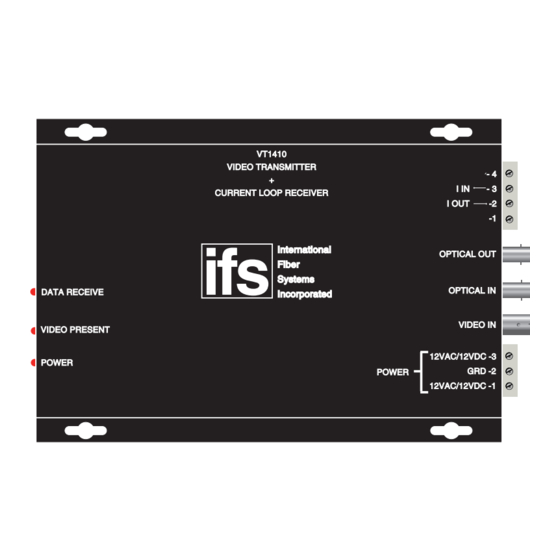
- Page 3 Video source VT1410 VIDEO TRANSMITTER I IN CURRENT LOOP RECEIVER I OUT International OPTICAL OUT Fiber Systems OPTICAL IN DATA RECEIVE Incorporated VIDEO IN VIDEO PRESENT 12VAC/12VDC -3 POWER GRD -2 POWER 12VAC/12VDC -1 VR1410 VIDEO RECEIVER + CURRENT LOOP XTMR...
- Page 4 VT1400 Data Receive LED illuminates B Video Present LED illuminates Power LED illuminates VR1400 Data In LED illuminates Video Out / AGC LED illuminates Power LED illuminates NOTE: WITHOUT PROPER FIBER CONNECTION, LED's DO NOT INDICATE CORRECT OPERATIONAL STATUS OF THE UNIT.
-
Page 5: Fcc Compliance
FCC Compliance This device complies with Part 15 of the FCC Rules. Operation is subject to the following two conditions: (1) This device may not cause harmful interference, and (2) this device must accept any interference received, including interference that may cause undesirable operation. Changes or modifications not expressly approved by International Fiber Systems, Inc. -
Page 6: Technical Support
888.329.0332 Note: Be ready at the equipment before calling. Online Another great resource for assistance with your Interlogix product is our online publication library. To access the library, go to our website at the following location: http://www.interlogix.com/transmission Many Interlogix documents are provided as PDFs (portable document format). To read these documents, you will... - Page 7 Product Disassembly Instructions for WEEE Per European Directive 2002/95/EC Waste Electrical and Electronic Equipment Required Tools: One number 2 Phillips (crosstip) screwdriver. One number 2 flat screwdriver. For the enclosed box version: 1. Locate and remove box cover securement screws. Usually, but not limited to, at least 4 screws.
- Page 8 Copyright © 2011 UTC Fire & Security. All rights reserved. Trademarks and Interlogix and IFS names and logos are trademarks of patents UTC Fire & Security. Other trade names used in this document may be trademarks or registered trademarks of the manufacturers or vendors of the respective products.