Crown CE-2000 Specifications
Architectural & engineering specifications ce series
Hide thumbs
Also See for CE-2000:
- Supplementary manual (1 page) ,
- Service manual (581 pages) ,
- Reference manual (52 pages)
Advertisement
Quick Links
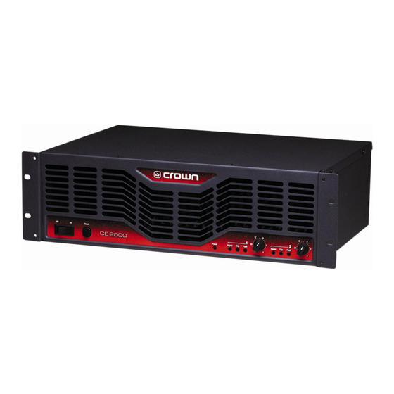
CE 2000
CE 2000 (60-Hz models)
®
The Crown
CE 2000 power amplifier shall be a solid-state two-channel
model.
The outputs shall be switchable as stereo or bridged-mono modes of
operation. The bridged-mono mode shall bridge the outputs to provide
increased output voltage.
The output impedance of each channel shall be less than 10 milliohms in
series with less than 2 microhenries in stereo mode.
The amplifier shall contain controlled slew-rate voltage circuitry to protect
it against radio frequency interference burnouts. It shall also be protected
from current overload at its output stage. The slew rate of the amplifier
shall be greater than 30 volts per microsecond in stereo mode.
The amplifier shall temporarily go into a stand-by mode if its power trans-
former becomes excessively hot and shall automatically resume normal
operation once it has cooled to a safe operating temperature.
Front-panel controls shall include an enable on/off switch, a detented input
level control for each channel and a reset switch.
Rear-mounted controls shall include an Input Sensitivity switch for each
channel to select between 1.4 V or a fixed voltage gain of 26 dB for full
rated output, a Mode switch to select whether the amp is in Bridge Mono
mode or Stereo mode, and an RJ-11 Fault output connector.
Front panel indicators shall include a green Power indicator to show the
amplifier has power, a red Clip indicator for each channel which shall turn
on when distortion of any type becomes audible in the amplifier output,
a red Fault indicator for each channel which will blink under 5 conditions:
1) When the amplifier is first turned powered up, until the unit is ready for
operation. 2) If the heatsinks reach a temperature above normal working
limits. 3) If the transformer thermal protection circuit is activated. 4) If the
amplifier wires develop a short circuit, and 5) should the amplifier output
stage become non-operational. There is also a green Signal indicator for
each channel which shall flash dimly when a low-level signal (> –40 dBm)
is present at the input of the amplifier.
C E
S E R I E S
Architectural & Engineering Specifications
The power amplifier shall meet or exceed the following performance
criteria. Input sensitivity for rated output: 26 dB voltage gain (unbalanced).
Rated FTC output in stereo mode with less than 0.1% THD: 400 watts per
channel (1 kHz) into 8 ohms. Hum and noise: at least 105 dB (A weighted)
below full rated output power. Frequency response: 20 Hz to 20 kHz, 0.1
dB at 1 watt into 8 ohms per channel in stereo mode. Damping factor:
greater than 400 from 10 to 400 Hz into 8 ohms. Phase response: 15 from
20 Hz to 20 kHz at 1 watt.
The amplifier shall be safe when driving any kind of load—even highly
reactive ones.
The power requirements shall be 120 VAC at 60 Hz. At idle, the amplifier
shall draw 90 watts or less.
The amplifier shall have a rugged steel chassis coated with environmentally
friendly powder.
The dimensions of the amplifier shall allow for 19 inch (48.3 cm) EIA
standard (RS-310-B) rack mounting. The amplifier shall be 5.25 inches
(13.34 cm) tall and 12.25 inches (31.11 cm) deep behind the rack-mount-
ing surface.
The amplifier shall weigh 40.3 pounds (18.28 kg) and shall have a center of
gravity approximately 6 inches (15.2 cm) behind the front panel.
The amplifier shall be designated the Crown CE 2000.
Crown International
1718 W. Mishawaka Rd.
Elkhart, IN 46517-9439
TEL: 574-294-8200
FAX: 574-294-8FAX
www.crownaudio.com
Specifications subject to change without prior notice. Latest
information available at www.crownaudio.com.
Crown and Crown Audio are registered trademarks of Crown
International, Inc. Printed in U.S.A.
© 2005 Crown Audio
, Inc.
®
04/05
138306-1
Advertisement


