Bryant TSTAT Installation And Start-Up Instructions Manual
Bryant installation and start-up instructions programmable thermoststate tstat
Hide thumbs
Also See for TSTAT:
- User manual (9 pages) ,
- Homeowner's manual (8 pages) ,
- Installation and start-up instructions manual (8 pages)
Table of Contents
Advertisement
NOTE: Read the entire instruction manual before starting the
installation.
This symbol
indicates a change since the last issue.
INDEX
SAFETY CONSIDERATIONS .....................................................1
INTRODUCTION ..........................................................................1
INSTALLATION CONSIDERATIONS .......................................1
INSTALLATION......................................................................1-12
Location .................................................................................1-2
Set Dip Switches ......................................................................2
Install Thermostat ..................................................................2-3
Set Thermostat Configuration ...............................................3-4
Check Thermostat Operation ................................................4-5
Final Settings ............................................................................5
Checklist....................................................................................5
WIRING DIAGRAMS .............................................................6-12
OPERATIONAL OPERATION ..................................................13
TROUBLESHOOTING ...............................................................13
CONFIGURATION RECORD....................................................14
SAFETY CONSIDERATIONS
Read and follow manufacturer instructions carefully. Follow all
local electrical codes during installation. All wiring must conform
to local and national electrical codes. Improper wiring or installa-
tion may damage thermostat.
Recognize safety information. This is the safety-alert symbol
When you see this symbol on the equipment and in the instruction
manual, be alert to the potential for personal injury.
Understand the signal words DANGER, WARNING, and CAU-
TION. These words are used with the safety-alert symbol. DAN-
GER identifies the most serious hazards which will result in severe
personal injury or death. WARNING signifies a hazard which
could result in personal injury or death. CAUTION is used to
identify unsafe practices which would result in minor personal
injury or product and property damage.
INTRODUCTION
Bryant's 7-day programmable thermostats are wall-mounted, low-
voltage thermostats which maintain room temperature by control-
ling the operation of a heating and air conditioning system.
Separate heating and cooling setpoints, plus auto changeover allow
setback programming for maximum energy savings. All of the
thermostats allow up to 4 time/temperature settings to be pro-
grammed per 24 hr period and store programs for 7 independent
days. Batteries are not required; during a power interruption, the
internal memory stores programs for an unlimited time and the
clock continues to run for at least 72 hrs.
INSTALLATION CONSIDERATIONS
POWER
Note that all TSTAT models require no batteries and are not
"power stealing". They do require 24VAC (R and C terminals) to
be connected for proper operation. Thermostat will not operate
without these 2 connections.
installation and
start-up instructions
PROGRAMMABLE THERMOSTATS
Page
.
—1—
Cancels: II TSTAT-0-11
As an ENERGY STAR Partner, Bryant Heating & Cooling
Systems has determined that this product meets the EN-
ERGY STAR guidelines for energy efficiency.
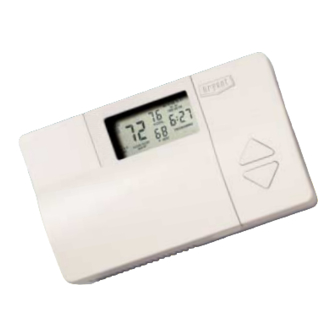
HEIGHT (IN.)
WIDTH (IN.)
4-1/4
Fig. 1—Bryant Programmable Thermostat
MODELS
There are 3 different models. The 9th and 10th letters of the part
number indicate the model. These 2 letters appear on the package
and on the circuit board. Be sure to have the proper thermostat for
the intended application. Models are:
AC - 1-stage cool, 1-stage heat - for AC systems only.
HP - 1-stage cool, 2-stage heat - for either HP or AC with 2-stage
heat.
2S - 2-stage cool, 2-stage heat - for 2-speed AC systems, or
2-stage cool, 3-stage heat - for 2-speed HP systems, or
1-stage cool, 4-stage heat - for 1-speed HP with special
3-stage electric heat.
Use each only for its intended purpose. (See Table 1.)
OUTDOOR TEMPERATURE SENSING
All Bryant programmable thermostats may be equipped with an
optional
outdoor
temperature
TSTATXXSEN01-B. If it is to be used, plan installation so that 2
wires can be run from the thermostat to an outdoor location,
preferably on the north side of the house OR refer to Installation
Instructions included with the outdoor temperature sensor for
simplified connection. Sensor can be mounted to outdoor unit and
existing control wires used for its connection. Details are provided
to the sensor instructions.
INSTALLATION
I. THERMOSTAT LOCATION
Thermostat should be mounted:
• Approximately 5 ft (1.5m) from floor.
TSTAT
II TSTAT-0-19
®
A98427
DEPTH (IN.)
7-1/2
1-3/8
sensor,
Part
9-98
No.
Advertisement
Table of Contents

Related Manuals for Bryant TSTAT


Summary of Contents for Bryant TSTAT
-
Page 1: Installation
72 hrs. INSTALLATION CONSIDERATIONS POWER Note that all TSTAT models require no batteries and are not "power stealing". They do require 24VAC (R and C terminals) to be connected for proper operation. Thermostat will not operate without these 2 connections. -
Page 2: Set Dip Switches
II. SET DIP SWITCHES There is a 4 section DIP switch within the thermostat which must be properly set by the installer. It is easiest to set these 4 switches before the thermostat is mounted to the wall, so STOP and complete the following steps: 1. - Page 3 B. To Enter Configuration Mode: Press and hold FAN button for approximately 10 sec until COOL set point display indicates a flashing 01. The thermostat is now in configuration mode. It will automatically exit this mode if no button is pressed for 3 minutes. Pressing END button will exit configuration mode immediately.
- Page 4 V. CHECK THERMOSTAT OPERATION Before doing the checkout, press HOLD button to turn on HOLD icon, locking thermostat in hold mode. This will assure set points don’t change during the checkout. Outputs for each stage of operation are listed in Table 2. In the table, the actual use of each terminal is underlined for terminals having double use.
- Page 5 If set point is raised more than 5° above room temperature, the staging timer is defeated and the thermostat will call for higher stages within 5 sec. Use this method if there are only 2 stages of heat. If more than 2 stages of heat are available, do not use this method because once the demand exceeds 5°, the thermostat may jump to the highest stage.
- Page 6 —6—...
- Page 7 Y1/W2 24 VAC COMM OUTDOOR SENSOR CONNECTION SUGGESTED DIP SWITCH SETTINGS OFF OFF OFF OFF Fig. 2—Single-Speed Air Conditioner with Single- Stage Furnace—Model AC Thermostat TWO-STAGE OR MODEL AC VARIABLE-SPEED THERMOSTAT FURNACE 24 VAC HOT HEAT STAGE 1 W/W1 W/W1...
- Page 8 Y1/W2 24 VAC COMM OUTDOOR SENSOR CONNECTION SUGGESTED DIP SWITCH SETTINGS OFF OFF OFF OFF Fig. 5—Single-Speed Air Conditioner with Typical Fan Coil—Model AC Thermostat (Single-Stage Heat Control) MODEL HP TYPICAL THERMOSTAT FAN COIL 24 VAC HOT RVS COOLING O/W2...
- Page 9 HEAT STAGE 2 COOL STAGE 1 24 VAC COMM OUTDOOR SENSOR CONNECTION OFF OFF ON OFF A98492 Fig. 10—Two-Speed Air Conditioner with Typical Fan Coil—Model 2S Thermostat MODEL 2S THERMOSTAT TWO-SPEED HEAT PUMP COOL/HEAT STAGE 1 RVS COOLING HEAT STAGE 3...
- Page 10 SENSOR CONNECTION See notes 3, 7, 8, 9, and 11 SUGGESTED DIP SWITCH SETTINGS OFF OFF OFF OFF Fig. 13—Two-Speed Heat Pump with Typical Fan Coil—Model 2S Thermostat MODEL AC THERMOSTAT EASY SELECT TERMINAL BOARD J1 JUMPER 24 VAC HOT...
- Page 11 24 VAC COMM OUTDOOR SENSOR CONNECTION SUGGESTED DIP SWITCH SETTINGS OFF OFF ON OFF Fig. 17—Two-Speed Air Conditioner with Variable-Speed Fan Coil (FK, FV) —Model 2S Thermostat SPLICE MODEL AC THERMOSTAT 24 VAC HOT HEAT STAGE 1 W/W1 COOL STAGE 1 Y/Y2...
- Page 12 MODEL HP SPLICE THERMOSTAT COOL STAGE 1 Y/Y2 HEAT STAGE 1 W/W1 RED (TRAN) Y1/W2 O/W2 HEAT STAGE 2 24 VAC HOT 24 VAC COMM OUTDOOR See notes 2, 10, 11, and 12 SENSOR CONNECTION SUGGESTED DIP SWITCH SETTINGS OFF OFF ON OFF Fig.
- Page 13 1. The AC model thermostat can only control 1-stage cool and 1-stage heat. Dip Switch-C on has no controlling function and can either be ON or OFF. 2. HP and 2S model thermostat MUST have Dip Switch-C ON when installed in air conditioner applications. If required, second-stage heat is controlled by O/W2.
- Page 14 ERROR CODES -- — If the thermostat cannot properly read room temperature, the display will indicate "--" (2 dashes) and all outputs (except the fan if on) will turn off. This is to prevent operation of the equipment if the thermostat has failed.
- Page 15 Room Temperature Offset (-5 to +5: factory default = 0) Enable Auto Mode (Off or On: factory default = On) D) Schedule WAKE TIME HEAT COOL TIME HEAT COOL TIME HEAT COOL TIME HEAT COOL Thermostat Model No. —15— Date SLEEP A98508...
- Page 16 Course descriptions and schedules are in our catalog. CALL FOR FREE CATALOG 1-800-962-9212 [ ] Packaged Service Training © 1998 Bryant Heating & Cooling Systems 7310 W. Morris St. Indianapolis, IN 46231 SERVICE TRAINING • Maintenance • Operating Sequence [ ] Classroom Service Training —16—...