Advertisement
Quick Links
Instruction manual
Safety precautions
This symbol
together with one of the following words "Danger"
or "Warning" indicates the risk level deriving from failure to observe the prescri-
bed safety precautions:
Warns that failure to observe the precautions
DANGER
risk of
involves a risk of electric shock.
electric shock
Warns that failure to observe the precautions involves
DANGER
a risk of damage to persons and/or things.
WARNING
Warns that failure to observe the precautions involves
the risk of damaging the pump and/or the plant.
1. General
The purpose of these instructions is to ensure the correct installation and best
performance of our pumps.
These are single cell centrifugal pumps with built-in filter elements, especially
designed for prefiltering and recirculation of water in swimming pools.
They are designed to operate with clean water at a maximum temperature of 40°C.
All materials used are of top quality; they are subjected to strict, controls and veri-
fied to extremely demanding standards.
Correct compliance with the installation and operation instructions, and with the
electrical connection diagrams, will prevent motor overloads and the consequen-
ces of all types that could otherwise result, consequences for which we decline all
responsability.
The appliance is not intended for use by young children or infirm
persons without supervision. Young children should be supervised to
ensure that they do not play with the appliance.
2. Installation
The installation of our electric pumps is only permitted in swimming pools or
ponds that meet DIN standards VDE 0100 part 702/11.82. In case of doubt,
inquire with an expert.
The pump should be installed as near as possible to water level, in
horizontal position, in order to obtain a minimum suction path and reduce
head losses.
It is not advisable to install the pump at more than 3 m geometrical height
from water level.
Independently of the geometrical height and the power of the model cho-
sen, self-priming times may be up to 10 min.
The pump must be fixed on a firm base, with screws of 6 or 8 mm
diameter, through the prepared holes in the foot.
The pump should be protected from possible flooding and receive dry
ventilation.The pump is to be installed in a manner consistent with the
National Wiring Rules.
3. Installing the lines
The supports of the suction and discharge lines will be independent of those of the
pump.
In the case of plastic lines, ensure tightness of joints and threads with TEFLON
tape alone. Glue or similar products should not be used.
The suction line should have a diameter equal to or greater than that of the
suction mouth of the pump.
The inside of the suction and discharge holes is threaded to a certain depth. This
depth should not be exceeded when screwing on the respective lines. Only new
or clean connectors should be used.
The suction lines should be structured with a slight slant to prevent the formation of
siphons.
4. Electrical connection
The electrical installation should have a multiple separation system with
contact opening of a least 3 mm.
The protection of the system will be based on an RCD (I fn = 30 mA). If
outdoor operation is foreseen, the power supply cord should meet EEC
standards (2) or be of type H07 RN-F as per VDE 0250.
Single-phase motors will be equipped with built-in thermal protection. In the
case of three-phase motors, the user should provide thermal protection
complying with the installation rules in force.
The diagrams in Fig. (1) will allow correct electrical connection.
5. Verifications prior to initial start-up
After making the connections defined in the preceeding section, unscrew
the filter cover and fill the pump prefilter with water to the bottom level of
the suction line.
Verify that the pump shaft turns freely.
Verify that the mains voltage and frequency match those specified on the
nameplate of the pump.
Set the prefilter cover back in place and screw it to a suitable tightness.
Check that the turning direction of the motor matches that specified on the
fan cover. In threephase motors, if the turning direction is incorrect, reverse
two supply phases on the protection panel.
If the motor does not start, try to determine the cause of the irregularity by
consulting the list of common faults and their possible solutions, provided in
this manual.
NEVER RUN THE PUMP DRY.
6. Starting
Open all the gate valves and put the motor under voltage. Wait a reasonable
time to allow self-priming. Verify the breakaway current and suitable adjust the
thermal relay.
7. Maintenance
Our pumps do not require any specific maintenance. It is advisable,
however, to periodically clean the pump filter and to empty the pump housing
in low-temperature periods through the blowoff plug. If the pump is to remain
idle, it is advisable to empty and clean it, and then reinstall the filter cover
with o ring lubricant on the rubber gasket, taking measures to ensure that the
place where the pump is to be stored will remain dry and ventilated.
In the event of breakdown, the user must in no event handle the pump, but
must contact an authorised technical service.
When the time comes to dispose of the pump, it contains no toxic or
contaminating materials. The principal components are duly identified for
selective breaking
.
If the supply cord is damaged, it must be replaced by the manufacturer or it's
service agent or a similarly qualified person in order to avoid a hazard.
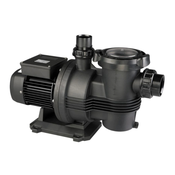
WHISPER Series
TYPHOON C-Series
TYPHOON T-Series
Swimming Pool Pumps
Advertisement

Summary of Contents for Monarch WHISPER Series
- Page 1 WHISPER Series TYPHOON C-Series TYPHOON T-Series Swimming Pool Pumps Instruction manual In the case of plastic lines, ensure tightness of joints and threads with TEFLON tape alone. Glue or similar products should not be used. Safety precautions The suction line should have a diameter equal to or greater than that of the suction mouth of the pump.
- Page 2 SINGLE PHASE SUPPLY 1 - RED 2 - WHITE 3 - BLACK 4 - CAPACITOR 5 - LINE 6 - MOTOR RELAY THREE PHASE SUPPLY 415 V 240 V Fig. 1 A 1 ∼ A 3 ∼ C – η Q max.
- Page 3 POSSIBLE FAULTS, THEIR CAUSES AND SOLUTIONS POSSIBLE PROBLEM SOLUTIONS 1) Pump does not prime. Air entry through suction line. Verify condition of connectors and gaskets of suction line. 2) Pump supplies Inadequate airtightness of filter cover. Clean the filter cover and verify condition of rubber gasket. scant flow.
- Page 4 7. Nothing in this guarantee is intended to have the effect of contracting out of the provisions of the Trade Practices Act (Aust.), the Goods and Consumer Protection Legislation of the various Australian states and Consumers Guarantee Act 1993 (NZ) except to the extent permitted by the various Acts and this guarantee is to be modified to the extent necessary to give effect to that intention.