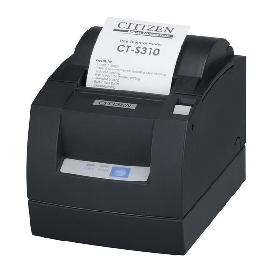
Citizen CT-S310 User Manual
Line thermal printer
Hide thumbs
Also See for CT-S310:
- User manual (136 pages) ,
- Command reference manual (512 pages) ,
- Command reference manual (312 pages)
Table of Contents
Advertisement
Advertisement
Table of Contents

Related Manuals for Citizen CT-S310


Summary of Contents for Citizen CT-S310
- Page 1 LINE THERMAL PRINTER MODEL CT-S310 User’s Manual...
-
Page 2: Declaration Of Conformity
CITIZEN is a registered trade mark of Citizen Holdings Co., Japan CITIZEN es una marca registrada de Citizen Holdings Co., Japón Company names and product names in this manual are trademarks or registered trademarks of relevant companies. Copyright c 2007 by Class A CITIZEN SYSTEMS JAPAN CO., LTD. - Page 3 IMPORTANT: This equipment generates, uses, and can radiate radio frequency energy and if not installed and used in accordance with the instruction manual, may cause interference to radio communications. It has been tested and found to comply with the limits for a Class A computing device pursuant to Subpart J of Part 15 of FCC Rules, which are designed to provide reasonable protection against such interference when operated in a commercial environment.
-
Page 4: General Precautions
Note that CITIZEN SYSTEMS is not responsible for any operation results regardless of missing, error, or misprinting in this manual. Note that CITIZEN SYSTEMS is not responsible for any trouble caused as a result of using options or consumables that are not specified in this manual. - Page 5 After having read this Manual, keep it in a safe, readily accessible place for future reference. Some of the descriptions contained in this manual may not be relevant to some printer models. In order to prevent injury hazard to operators, third parties or damage to property, special warning symbols are used in this user’s manual to indicate important items to be strictly...
- Page 6 • Neglecting these warnings may result in printer failure, overheating, emission of smoke, fire, or electric shock. Do not drop any foreign object nor spill liquid into the printer. Do not place any object on the printer either. Do not drop any metallic object such as paper clip, pin or screw into the printer.
- Page 7 A state where any object is placed on the printer A state where the printer is covered or wrapped by a cloth or bed clothing • Be careful about internal heat buildup, which could cause fire and deform the case.
- Page 8 • The printer may not be immediately shut down in an emergency. Insert the power plug fully into the outlet. If the printer is not to be used for a long time, leave it disconnected from its supply outlet. Hold the plug and connector when plugging or unplugging the power cord or signal cable after turning off the printer and the appliance connected to it.
- Page 9 Do not touch any of the moving parts (e.g., paper cutter, gears, active electrical parts) while the printer is working. In case of trouble do not attempt to repair the printer. Ask CITIZEN SYSTEMS service for repair. Be careful that the paper cover does not entrap your hands or fingers.
-
Page 10: Daily Maintenance
DAILY MAINTENANCE Observe the following precautions for daily maintenance. When cleaning the printer, always turn it off and unplug it from the supply outlet. Use a soft, dry cloth for cleaning the surface of the printer case. For severe stains, use a soft cloth slightly dampened with water. -
Page 11: Table Of Contents
1.1 Features ...9 1.2 Unpacking ...10 1.3 Model Classification ... 10 1.4 Basic Specifications ... 11 2. EXPLANATION OF PRINTER PARTS... 12 2.1 Printer Appearance ... 12 2.2 Paper Cover Inside ... 14 2.3 Other Built-in Functions ... 14 3. PREPARATION ... 15 3.1 Connecting the AC Adapter and AC Power Cord ... -
Page 12: General Outline
1. GENERAL OUTLINE The CT-S310 is a thermal line printer designed for use with a broad array of terminal equipment including, data, POS, and kitchen terminals. With extensive features, it can be used in a wide range of applications. 1.1 Features ●... -
Page 13: Unpacking
1.2 Unpacking When unpacking the printer, confirm that the following are provided: Printer: AC adapter (AC adapter type): AC power cord: Sample paper roll: Partition for 58-mm wide paper roll: User’s manual (This manual): Printer (AC adapter type) Printer (Built-in power supply type) 1.3 Model Classification... -
Page 14: Basic Specifications
*1: Value in parentheses shows the case when a 58-mm wide paper roll is used. *2: The number of printable columns is selectable with a DIP switch. *3: Represents the safety standards acquired when CITIZEN SYSTEMS-made adapters (35AD2 series) are used. -
Page 15: Explanation Of Printer Parts
To refill or replace paper, open the paper cover by pulling this lever fully to the root. Power switch This switch turns the printer power ON/OFF. Cutter lock releasing feed hole When the cutter blade is kept protruded after abnormal termination or paper jam, the paper cover cannot be opened. - Page 16 Operation Panel POWER LED Lights when the printer power is on and goes off when the printer power is off. May blink or light in a special mode or in case of a failure. ERROR LED Lights or blinks when paper is empty or in case of a failure.
-
Page 17: Paper Cover Inside
Stops printing when this sensor detects paper end. 2.3 Other Built-in Functions Buzzer This printer has a built-in buzzer. It is operated in case of an error, operation, or by a command. User memory Allows registration of user-defined characters and logo data on the nonvolatile memory. -
Page 18: Preparation
Keep the power cord away from heat generating appliances. Otherwise the shield of power cord may be fused resulting in a fire or electric shock. If the printer is not to be used for a long time, leave it disconnected from its supply outlet. -
Page 19: Connecting Interface Cables
3.2 Connecting Interface Cables Turn off the printer power and unplug the power connector. Then follow the procedure for interface cable connection. Orient the interface cable terminal correctly and insert it into the interface connector. In case of a built-in power supply type, remove the power box unit before connection. -
Page 20: Connecting The Cash Drawer
3.3 Connecting the Cash Drawer 1. Turn off the printer power. 2. Orient the cash drawer cable connector correctly, insert it into the cash drawer interface connector on the back of the printer. 3. Connect the drawer‘s ground line to the printer‘s ground terminal with a screw. -
Page 21: Installing The Printer
Horizontal position CAUTION! When used in vertical position, the printer ejects paper not to fall naturally even with full cutting. Be careful in using the printer built in equipment, etc. When using in horizontal setting, avoid cutting full. Otherwise, the cut paper may drop into the cutter and may result in double cutting and narrow pieces of paper. -
Page 22: Setting Dip Switch
3.6 Setting DIP Switch The DIP switch is present on the serial interface. Remove the board fixing screws, take out the interface board, and then set the DIP switch. The function of each switch is as shown below. Switch No. Function Communication condition DIP switch setting setting method... -
Page 23: Adjusting The Paper Near-End Sensor
2. Move the paper near-end sensor unit to the right and left while pushing it. The position to be set varies in accordance with the setting of the printer, horizontal or vertical, or the diameter of the paper roll as shown in the following figure. -
Page 24: Maintenance And Troubleshooting
3. Remove the jammed paper including any paper chips remaining. (Also take out the paper roll from the holder.) 4. Turn on the printer. The auto cutter mechanism is initialized and the alarm is cleared. CAUTION! The print head is hot immediately after printing. -
Page 25: Cleaning The Print Head
4.3 Cleaning the Print Head 1. Turn the printer power off. 2. Open the paper cover. 3. Wait several minutes. Wipe off any debris on the heating element of the head using a cotton swab soaked in ethyl alcohol. CAUTION! The print head is hot immediately after printing. -
Page 26: Self-Printing
Insert paper into the printer. With the FEED switch pressed and held, turn the printer power on, keep the FEED switch held for about 1 second, and then release the FEED switch. The printer starts self-printing. The printer prints model name, version, DIP switch setting, memory switch setting, and built-in fonts. -
Page 27: Error Indication
When you print dense characters or dark image, the head temperature rises. If the head temperature exceeds a specified level, the printer stops printing operation and waits till the head temperature is lowered. During waiting, the ERROR lamp blinks. When the head temperature is lowered, printing resumes automatically. -
Page 28: Other
5. OTHER 5.1 External Views and Dimensions AC Adapter Type 5.2 Manual Setting of Memory Switch Memory switches can be set manually or by a command. For manual setting, refer to the next page. The function of each memory switch is shown in the following table. (The white-on-black characters Switch No. -
Page 29: Manual Setting Of Memory Switch
Level 6, Level 7, Level 8, Level 9 — 26 — Invalid − Invalid Black MK 42/30 col − Valid Command Valid Back Valid − − − − Valid Invalid − Printer Class − − − Set Paper − Set Values... - Page 30 When you press the FEED button long, the set value is accepted and then the printer goes to the next setting item. (No indication for 0/1 with memory switch ranging from 7 to 10) —...
-
Page 31: Printing Paper
Returning to the memory switch select mode When the setting of the desired content is completed, open the printer cover and then close the printer cover. This allows the printer to print the setting of the changed memory switch. Saving the setting and exiting the memory switch setting mode Press the FEED button short to move to “Save To Memory”. - Page 32 TC74906-10F 1.10-0802 Printed in Japan...