
Related Manuals for Cisco SRW2016


Summary of Contents for Cisco SRW2016
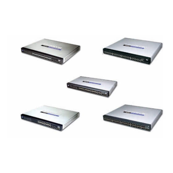
- Page 1 USER GUIDE BUSINESS SERIES WebView Switches SRW2048, SRW2024, SRW2016, SRW248G4, SRW224G4 Model:...
-
Page 2: About This Guide
Network Security www.linksys.com/security Copyright and Trademarks Linksys is a registered trademark or trademark of Cisco Systems, Inc. and/ or its affiliates in the U.S. and certain other countries. Copyright © 2008 Cisco Systems, Inc. All rights reserved. Other brands and product names are trademarks or registered trademarks of their respective holders. -
Page 3: Table Of Contents
Configuring the Switch ........ - Page 4 Chapter 5: Advanced Configuration Overview ...........20 Accessing the Web-based Utility .
- Page 5 Security > RADIUS ..........36 Security >...
- Page 6 Admin > Static Address......... .56 Admin >...
- Page 7 User Information for Consumer Products Covered by EU Directive 2002/96/EC on Waste Electric and Electronic Equipment (WEEE) ......78 Appendix H: Software License Agreement Software in Linksys Products: .
-
Page 8: Chapter 1: Introduction
10/100/1000 RJ-45 ports and 2 shared SFP (MiniGBIC) slots. For the purpose of this manual, whenever a feature applies to all models, the name WebView Switch will be referenced. If a specific model number is mentioned, then the feature is specific to that model. -
Page 9: Chapter 2: Product Overview
Chapter 2 Chapter 2: Product Overview SRW2048 Front Panel The Switch’s LEDs and ports are located on the front panel. Front Panel of the SRW2048 LEDs POWER (Green) Lights up green to indicate that power is being supplied to the Switch. -
Page 10: Srw2024
If you need to reset the Switch, unplug the power cord from the back of the Switch. Wait a few seconds and then reconnect it. SRW2024 Front Panel The Switch’s LEDs and ports are located on the front panel. Front Panel of the SRW2024 LEDs POWER (Green) Lights up green to indicate that power is being supplied to the Switch. -
Page 11: Srw2016
On the SRW2016, MiniGBIC ports are shared with standard ports. If a miniGBIC port is used, then the shared standard port on the Switch cannot be used. The following table provides port mapping details of the SRW2016 Switch. SRW2016 Shared Port Mapping miniGBIC Port... -
Page 12: Srw248G4
If you need to reset the Switch, unplug the power cord from the back of the Switch. Wait a few seconds and then reconnect it. SRW248G4 Front Panel The Switch’s LEDs and ports are located on the front panel. Front Panel of the SRW248G4 LEDs POWER (Green) Lights up green to indicate that power is being supplied to the Switch. -
Page 13: Srw224G4
If you need to reset the Switch, unplug the power cord from the back of the Switch. Wait a few seconds and then reconnect it. SRW224G4 Front Panel The Switch’s LEDs and ports are located on the front panel. Front Panel of the SRW224G4 LEDs POWER (Green) Lights up green to indicate that power is being supplied to the Switch. - Page 14 CONSOLE The Switch is equipped with a serial port labeled Console (located on the back of the switch) that allows you to connect to a computer’s serial port (for configuration purposes) using the provided serial cable. You can use HyperTerminal to manage the Switch using the console port.
-
Page 15: Chapter 3: Connecting The Switch
WebView Switches Placement Options There are two ways to physically install the Switch, either set the Switch on its four rubber feet for desktop placement or mount the switch in a standard-sized, 482.6-mm wide, 1U-high rack for rack-mount placement. Desktop Placement •... -
Page 16: Hardware Installation
Switch. Power on the network devices connected to the Switch. Each active port’s corresponding Link/Act LED will light up on the Switch. If a port has an active Gigabit connection, then its corresponding Gigabit LED will also light up. -
Page 17: Chapter 4: Configuration Using The Console Interface
Console Interface Overview The Switch features a menu-driven console interface for basic configuration of the Switch and management of your network. The Switch can be configured using CLI through the console interface or through a Telnet connection. This chapter describes console interface configuration. -
Page 18: Configuring The Switch Through The Console Interface
User & Password Settings Security Settings IP Configuration File Management Restore System Default Settings Reboot System Back to main menu System Configuration Menu System Information Using System Information screen, you can check the Switch’s firmware versions and general system information. System Configuration Menu... - Page 19 Chapter 4 Versions The Versions screen displays the Switch’s boot, software, and hardware firmware versions. Versions General System Information The General System Information screen displays general information about the Switch. General System Information Select Edit and press the Enter key to make changes.
- Page 20 Chapter 4 Telnet Configuration The Telnet Configuration screen displays the timeout value. The value is entered in seconds. If you do not want the Telnet session to timeout, you may enter a value of 0 sec. Telnet Configuration Select Edit and press the Enter key to make changes. When your changes are complete, press the Esc key to return to the Action menu.
- Page 21 The Username & Password Settings screen can also be used to set passwords for other users. Security Settings The Security Settings screen enables you to configure security settings on the Switch, as well as generate and display the certificate. Security Settings...
- Page 22 Chapter 4 SSL Certificate Generation Use the Certificate Generation screen to specify a device- generated certificate. SSL Certificate Generation Public Key Length Specifies the SSL RSA key length. (Range: 512–2048) Organization Name Specifies the organization name. (Range: 1–64) Locality or City Name Specifies the location or city name.
- Page 23 DHCP client The status of the DHCP client is displayed. If you want the Switch to be a DHCP client, then select ENABLE. If you want to assign an static IP address to the Switch, then enter the IP settings and select DISABLE.
- Page 24 Chapter 4 Network Configuration The Network Configuration screen offers a choice of two tests: Ping and TraceRoute. Network Configuration Ping The Ping screen displays the IP address of the location you want to contact. Ping Test Select Edit to change the IP address, and select Execute to begin the ping test.
-
Page 25: Port Status
Reboot System Select Reboot System and press the Enter key if you want to restart the Switch. You will be asked if you want to continue. Press the y key to reboot the Switch, or press the n key to cancel. After the Switch has rebooted, the Switch Main Menu screen will appear. -
Page 26: Port Configuration
Configuration Using the Console Interface Chapter 4 Port Configuration On the Switch Main Menu screen, select Port Configuration and press the Enter key if you want to configure the Switch’s ports. The Port Configuration screen displays the port numbers, their status, auto-negotiation status, speed and duplex mode, and status of flow control, which is the flow of packet transmissions. -
Page 27: Chapter 5: Advanced Configuration
WebView Switches. The screen images were taken from the SRW2048 Switch. Additional features for specific Switches are noted. The SRW224G4, SRW248G4, SRW2016, and SRW2024 Switches may not support all functions. Accessing the Web-based Utility... -
Page 28: System Information
By default, a system name is not defined. System Location This field is used to enter a description of where the Switch is physically located, such as 3rd Floor. System Contact Enter the name of the administrator responsible for the system. -
Page 29: Setup > Time
Daylight Saving Daylight Saving Select Daylight Saving to enable it on the Switch. If the Switch should use US daylight savings, then select USA. If the Switch should use EU daylight savings, then select European. If it should use another kind of daylight savings, then select Custom and complete the From and To fields. -
Page 30: Setup > Green Ethernet
Green network. This feature has been added to version 1.1 of SRW2048 and to version 1.3 of SRW2024 and SRW2016. Setup > Green Ethernet Energy Saving Mode Indicates if Green Ethernet is enabled on the device. -
Page 31: Port Settings > Port Configuration
MDIX, or Auto (automatically detect type). The MDI setting is used if the port is connected to an end station. The MDIX setting is used if the port is connected to a hub or another switch. Current MDI/MDIX (Read-only) The port’s current MDI/ MDIX type. -
Page 32: Port Management > Link Aggregation
Chapter 5 When a port is a Private VLAN Edge (PVE) port, it bypasses the Forwarding Database and forwards all unicast, multicast, and broadcast traffic to an uplink. NOTE: All ports in the same PVE group should join the same VLAN group. (Read-only) The LAG to which this port belongs, if the port is a LAG member. -
Page 33: Port Management > Lacp
Long is the default. Admin Key A channel will only be formed between ports having the same admin key. This only applies to ports located on the same switch. WebView Switches Advanced Configuration VLAN Management > Create VLAN The Create VLAN screen provides information and global parameters for configuring and working with VLANs. -
Page 34: Vlan Management > Port Setting
Chapter 5 VLAN Management > Port Setting The VLAN Port Setting screen provides parameters for managing ports that are part of a VLAN. The port default VLAN ID (PVID) is configured on the VLAN Port Setting screen. All untagged packets arriving to the device are tagged by the ports PVID. -
Page 35: Vlan Management > Vlan To Ports
Chapter 5 VLAN Management > VLAN to Ports The VLAN to Ports screen contains fields for configuring VLANs to a ports. VLAN Management > VLAN to Ports Port Displays the interface number. Mode Indicates the port-to-VLAN mode. The possible field values are: •... -
Page 36: Statistics > Rmon Statistics
Chapter 5 Statistics > RMON Statistics The RMON Statistics screen contains fields for viewing information about device utilization and errors that occurred on the device. Statistics > RMON Statistics Interface Indicates the device for which statistics are displayed. The possible field values are: Port Defines the specific port for which RMON •... -
Page 37: Statistics > Rmon History
Chapter 5 Statistics > RMON History The RMON History screen contains information about samples of data taken from ports. For example, the samples may include interface definitions or polling periods. Statistics > RMON History The RMON History Control screen is divided into RMON History and Log Table. -
Page 38: Statistics > Rmon Alarm
Chapter 5 Undersize Packets Displays the number of undersized packets (less than 64 octets) received on the interface since the device was last refreshed. Oversize Packets Displays the number of oversized packets (over 1518 octets) received on the interface since the device was last refreshed. -
Page 39: Statistics > Rmon Events
Chapter 5 Counter Value Displays the current counter value for the particular alarm. Statistics > RMON Events The RMON Events screen contains fields for defining RMON events. Statistics > RMON Events Add Event Event Entry Displays the event. Community Displays the community to which the event belongs. -
Page 40: Statistics > 802.1X Statistics
Chapter 5 Statistics > 802.1x Statistics The 802.1X Statistic screen contains information about EAP packets received on a specific port. Statistics > 802.1x Statistics Port Indicates the port, which is polled for statistics. Refresh Rate Indicates the amount of time that passes before the EAP statistics are refreshed. -
Page 41: Acl > Ip Based Acl
Chapter 5 The GVRP Error Statistics Table contains the following fields: Invalid Protocol ID Displays the device GVRP Invalid Protocol ID statistics. Invalid Attribute Type Displays the device GVRP Invalid Attribute ID statistics. Invalid Attribute Value Displays the device GVRP Invalid Attribute Value statistics. -
Page 42: Acl > Mac Based Acl
Chapter 5 Source Port Defines the TCP/UDP source port to which the ACE is matched. This field is active only if 800/6-TCP or 800/17-UDP are selected in the Select from List drop-down menu. The possible field range is 0–65,535. Destination Port Defines the TCP/UDP destination port. -
Page 43: Security > Acl Binding
Chapter 5 Ether Type Specifies the packet’s Ethernet type. Use the Add to List button to add the configured MAC Based ACLs to the MAC Based ACL Table at the bottom of the screen. Security > ACL Binding When an ACL is bound to an interface, all the ACE rules that have been defined are applied to the selected interface. -
Page 44: Security > Tacacs
Chapter 5 802.1X Indicates that the RADIUS server is used for • 802.1X authentication. • Indicates that the RADIUS server is used for authenticating user name and passwords, and 802.1X port authentication. Use the Add to List button to add the RADIUS configuration to the RADIUS Table at the bottom of the screen. -
Page 45: 802.1X Settings > Setting Timer
(Range: 300–4,294,967,295). The field default is 3600 seconds. Quiet Period Specifies the number of seconds that the switch remains in the quiet state following a failed authentication exchange (Range: 0–65,535). Resending EAP Specifies the number of seconds that the switch waits for a response to an EAP - request/identity frame, from the supplicant (client), before resending the request. -
Page 46: Security > Multiple Hosts
Chapter 5 Learning Mode Defines the locked port type. The Learning Mode field is enabled only if Locked is selected in the Interface Status field. The possible field values are: Classic Lock Locks the port using the classic lock • mechanism. -
Page 47: Security > Storm Control
Disables QoS on the interface. Basic • Enables QoS on the interface. Advanced • Enables Advanced mode QoS on the interface. This feature has been added to version 1.2 of the SRW2024/SRW2016 and version 1.1 of the SRW224G4/SRW248G4. Advanced Configuration QoS > CoS Settings... -
Page 48: Cos Default
Modifying queue scheduling affects the queue settings globally. The Bandwidth screen is not used with the Service mode, as bandwidth settings are based on services. This feature has been added to version 1.2 of the SRW2024/ SRW2016 and version 1.1 of the SRW224G4/SRW248G4. QoS > Bandwidth... -
Page 49: Qos > Basic Mode
The rules are based on the ACLs (see Access Control Tab). This feature has been added to version 1.2 of the SRW2024/SRW2016 and version 1.1 of the SRW224G4/SRW248G4. Indicates if rate MAC ACLs and IP ACLs can be grouped together in more complex structures, called policies. -
Page 50: Advanced Mode > Policy Name
Chapter 5 Use the Policy Settings button to open the Policy Name screen. Advanced Mode > Policy Name Advanced Mode > Policy Name Policy Name Defines a new Policy name. Add to List The Add to List button lets you add the policy to the Policy Name table. -
Page 51: Spanning Tree > Stp Status
Chapter 5 Spanning Tree > STP Status The STP Status screen describes the STP status on the device. Spanning Tree > STP Status Spanning Tree State Indicates if STP is enabled on the device. Spanning Tree Mode Indicates the STP mode by which STP is enabled on the device. -
Page 52: Bridge Settings
Chapter 5 Path Cost Default Values Specifies the method used to assign default path costs to STP ports. The possible field values are: Short Specifies a 1–65,535 range for port path costs. • This is the default value. • Long Specifies a 1–200,000,000 range for port path costs. -
Page 53: Spanning Tree > Rstp Port Settings
Provides the lowest cost path to forward packets to root switch. Designated Indicates that the port or LAG via which • the designated switch is attached to the LAN. • Alternate Provides an alternate path to the root switch from the root interface. -
Page 54: Spanning Tree > Mstp Properties
The link remains configured for communications until explicit LCP or NCP packets close the link, or until some external event occurs. This is the actual switch port link type. It may differ from the administrative state. Disabled Disables point-to-point link. -
Page 55: Spanning Tree > Mstp Instance Settings
Chapter 5 Spanning Tree > MSTP Instance Settings MSTP operation maps VLANs into STP instances. Packets assigned to various VLANs are transmitted along different paths within Multiple Spanning Trees Regions (MST Regions). Regions are one or more Multiple Spanning Tree bridges by which frames can be transmitted. In configuring MST, the MST region to which the device belongs is defined. -
Page 56: Multicast > Igmp Snooping
Chapter 5 Alternate Provides an alternate path to the root • device from the root interface. • Backup Provides a backup path to the designated port path toward the Spanning Tree leaves. Backup ports occur only when two ports are connected in a loop by a point-to-point link. -
Page 57: Multicast > Bridge Multicast
IGMP group and not receiving a Join message from another station, before timing out. If a Leave Timeout occurs, the switch notifies the Multicast device to stop sending traffic The Leave Timeout value is either user-defined, or an immediate leave value. -
Page 58: Snmp > Global Parameters
Chapter 5 SNMP > Global Parameters The Global Parameters screen contains parameters for defining SNMP notification parameters. SNMP > Global Parameters Local Engine ID Indicates the local device engine ID. The field value is a hexadecimal string. Each byte in hexadecimal character strings consists of two hexadecimal digits. -
Page 59: Snmp > Group Profile
Chapter 5 SNMP > Group Profile The Group Profile screen provides information for creating SNMP groups and assigning SNMP access control privileges to SNMP groups. Groups allow network managers to assign access rights to specific device features, or features aspects. SNMP >... -
Page 60: Snmp > Communities
Chapter 5 Authentication Key Defines the HMAC-MD5-96 or HMAC-SHA-96 authentication level. The authentication and privacy keys are entered to define the authentication key. If only authentication is required, 16 bytes are defined. If both privacy and authentication are required, 32 bytes are defined. -
Page 61: Base Table
Chapter 5 Base Table Management Station Displays the management station IP address for which the basic SNMP community is defined. Community String Displays the password used to authenticate the management station to the device. Access Mode Displays the access rights of the community. -
Page 62: Snmp > Notification Recipient
Chapter 5 SNMP > Notification Recipient The Notification Recipient screen contains information for defining filters that determine whether traps are sent to specific users, and the trap type sent. SNMP notification filters provide the following services: • Identifying Management Trap Targets •... -
Page 63: Admin > Jumbo Frames
Admin > Static Address A static address can be assigned to a specific interface on this switch. Static addresses are bound to the assigned interface and cannot be moved. When a static address is seen on another interface, the address will be ignored and will not be written to the address table. -
Page 64: Admin > Dynamic Address
The Dynamic Address Table contains the MAC addresses learned by monitoring the source address for traffic entering the switch. When the destination address for inbound traffic is found in the database, the packets intended for that address are forwarded directly to the associated port. -
Page 65: Admin > Port Mirroring
Port mirroring can be used as diagnostic tool and/or a debugging feature. Port mirroring also enables switch performance monitoring. Admin > Port Mirroring Network administrators configure port mirroring by selecting a specific port to copy all packets, and different ports from which the packets are copied. -
Page 66: Admin > Save Configuration
Chapter 5 Admin > Save Configuration Admin > Save Configuration Via TFTP Upgrade Select this option to upgrade the switch from a file located on a TFTP server. TFTP Server The TFTP Server IP Address that contains • the source file to upgrade from. -
Page 67: Admin > Reboot
Admin > Reboot Admin > Factory Defaults The Factory Reset screen allows network managers to reset the device to the factory defaults shipped with the switch. Restoring factory defaults results in erasing the configuration file. Admin > Factory Defaults NOTE:... -
Page 68: Admin > Memory Logs
Chapter 5 Admin > Memory Logs The Memory Log screen contains all system logs in a chronological order that are saved in RAM (Cache). Admin > Memory Logs Log Index Displays the log number. Log Time Displays the time at which the log was generated. -
Page 69: Appendix A: About Gigabit Ethernet And Fiber Optic Cabling
Each fiber optic cable is tipped with a connector that fits into a fiber port on a network adapter, hub, or switch. In the USA, most cables use a square SC connector that slides and locks into place when plugged into a port or connected to another cable. -
Page 70: Appendix B: Windows Help
Windows Help Appendix B Appendix B: Windows Help Almost all networking products require Microsoft Windows. Windows is the most used operating system in the world and comes with many features that help make networking easier. These features can be accessed through Windows Help and are described in this appendix. -
Page 71: Appendix C: Downloading Using Xmodem
Chapter 4: Configuration Using the Console Interface to configure HyperTerminal to connect to the Switch. Power on the Switch and watch for the auto-boot message: Autoboot in 2 seconds - press RETURN or Esc. to abort and enter prom. - Page 72 Downloading using Xmodem Appendix C Press Send and the software is downloaded. Download After the software has been downloaded, the device will reboot automatically. WebView Switches...
-
Page 73: Appendix D: Glossary
Appendix D Appendix D: Glossary This glossary contains some basic networking terms you may come across when using this product. WEB: For additional terms, please visit the glossary at www.linksys.com/glossary Access Mode Specifies the method by which user access is granted to the system. Access Point A device that allows wireless-equipped computers and other devices to communicate with a wired network. - Page 74 For example, to report a processing error. IGMP (Internet Group Management Protocol) Allows hosts to notify their local switch or router that they want to receive transmissions assigned to a specific multicast group.
- Page 75 Switch Filters and forwards packets between LAN segments. Switches support any packet protocol type. TACACS+ (Terminal Access Controller Access Control System Plus) Proprietary Cisco enhancement to Terminal Access Controller Access Control System (TACACS). Provides additional support for authentication, authorization, and accounting.
- Page 76 Glossary Appendix D TCP (Transmission Control Protocol) A network protocol for transmitting data that requires acknowledgement from the recipient of data sent. TCP/IP (Transmission Control Protocol/Internet Protocol) A set of instructions PCs use to communicate over a network. Telnet A user command and TCP/IP protocol used for accessing remote PCs.
-
Page 77: Appendix E: Specifications
RMON probe WebView Switches Specifications Other Management RFC854 Telnet (Menu-driven configuration) Secure Shell (SSH) and Telnet Management Telnet Client SSL security for Web UI Switch Audit Log DHCP Client BootP SNTP Xmodem upgrade Cable Diagnostics PING Traceroute Security features IEEE 802.1x 802.1x - RADIUS... - Page 78 –4 to 158°F (–20 to 70°C) Operating Humidity 10% to 90% Storage Humidity 10% to 95% WebView Switches Specifications SRW2016/SRW2024 Standards IEEE 802.3, 802.3u, 802.3ab, 802.3x, 802.1p, 802.1q Ports 16 or 24 10/100/1000 RJ-45 ports and 2 shared SFP (miniGBIC) slots...
- Page 79 Other Management RFC854 Telnet (Menu-driven configuration) Secure Shell (SSH) and Telnet Management RADIUS TACACS+ Telnet Client SSL security for Web UI Switch Audit Log DHCP Client BootP SNTP Xmodem upgrade Cable Diagnostics PING Traceroute Syslog Security Features IEEE 802.1x 802.1x - RADIUS Authentication.
- Page 80 RMON probe WebView Switches Specifications Other Management RFC854 Telnet (Menu-driven configuration) Secure Shell (SSH) and Telnet Management Telnet Client SSL security for Web UI Switch Audit Log DHCP Client BootP SNTP Xmodem upgrade Cable Diagnostics PING Traceroute Syslog Security IEEE 802.1x...
- Page 81 Priority levels 4 Hardware queues Scheduling Priority Queueing and Weighted Round Robin (WRR) Class of Service Port-based 802.1p VLAN priority based IP TOS/DSCP based IPv4 & IPv6 Traffic Class based MAC Address port security VLAN ID MAC Address IP Address Subnet Mask Service Type Protocol...
-
Page 82: Appendix F: Warranty Information
Appendix F Appendix F: Warranty Information Limited Warranty Linksys warrants this Linksys hardware product against defects in materials and workmanship under normal use for the Warranty Period, which begins on the date of purchase by the original end-user purchaser and lasts for the period specified for this product at www.linksys.com/warranty. -
Page 83: Technical Support
Warranty Information Appendix F product to Linksys at your cost and risk. You must include the RMA number and a copy of your dated proof of original purchase when returning your product. Products received without a RMA number and dated proof of original purchase will be rejected. -
Page 84: Appendix G: Regulatory Information
Appendix G Appendix G: Regulatory Information FCC Statement This equipment has been tested and complies with the specifications for a Class A digital device, pursuant to Part 15 of the FCC Rules. Operation is subject to the following two conditions: (1) this device may not cause harmful interference, and (2) this device must accept any interference received, including interference that may cause undesired operation. -
Page 85: User Information For Consumer Products Covered By Eu Directive 2002/96/Ec On Waste Electric And Electronic Equipment (Weee)
Appendix G User Information for Consumer Products Covered by EU Directive 2002/96/EC on Waste Electric and Electronic Equipment (WEEE) This document contains important information for users with regards to the proper disposal and recycling of Linksys products. Consumers are required to comply with this notice for all electronic products bearing the following symbol: English - Environmental Information for Customers in... - Page 86 Appendix G Eesti (Estonian) - Keskkonnaalane informatsioon Euroopa Liidus asuvatele klientidele Euroopa Liidu direktiivi 2002/96/EÜ nõuete kohaselt on seadmeid, millel on tootel või pakendil käesolev sümbol keelatud kõrvaldada koos sorteerimata olmejäätmetega. See sümbol näitab, et toode tuleks kõrvaldada eraldi tavalistest olmejäätmevoogudest.
- Page 87 Appendix G Lietuvškai (Lithuanian) - Aplinkosaugos informacija, skirta Europos Sąjungos vartotojams Europos direktyva 2002/96/EC numato, kad įrangos, kuri ir kurios pakuotė yra pažymėta šiuo simboliu (įveskite simbolį), negalima šalinti kartu su nerūšiuotomis komunalinėmis atliekomis. Šis simbolis rodo, kad gaminį reikia šalinti atskirai nuo bendro buitinių...
- Page 88 Appendix G Português (Portuguese) - Informação ambiental para clientes da União Europeia A Directiva Europeia 2002/96/CE exige que o equipamento que exibe este símbolo no produto e/ou na sua embalagem não seja eliminado junto com os resíduos municipais não separados. O símbolo indica que este produto deve ser eliminado separadamente dos resíduos domésticos regulares.
-
Page 89: Appendix H: Software License Agreement
Appendix H: Software License Agreement Software in Linksys Products: This product from Cisco-Linksys LLC or from one of its affiliates Cisco Systems-Linksys (Asia) Pte Ltd. or Cisco- Linksys K.K. (“Linksys”) contains software (including firmware) originating from Linksys and its suppliers and may also contain software from the open source community. -
Page 90: Schedule 2
Appendix H your Linksys product and/or the Software is being used in accordance with the terms of this Agreement; (iii) to provide improvements to the way Linksys delivers technology to you and to other Linksys customers; (iv) to enable Linksys to comply with the terms of any agreements it has with any third parties regarding your Linksys product and/or Software and/or (v) to enable Linksys to comply with all... - Page 91 Appendix H Preamble The licenses for most software are designed to take away your freedom to share and change it. By contrast, the GNU General Public License is intended to guarantee your freedom to share and change free software--to make sure the software is free for all its users.
- Page 92 Appendix H c) If the modified program normally reads commands interactively when run, you must cause it, when started running for such interactive use in the most ordinary way, to print or display an announcement including an appropriate copyright notice and a notice that there is no warranty (or else, saying that you provide a warranty) and that users may redistribute the program under these conditions, and telling the user how to...
-
Page 93: Schedule 3
Appendix H License and any other pertinent obligations, then as a consequence you may not distribute the Program at all. For example, if a patent license would not permit royalty- free redistribution of the Program by all those who receive copies directly or indirectly through you, then the only way you could satisfy both it and this License would be to refrain entirely from distribution of the Program. - Page 94 Appendix H Copyright (c) 1998-2007 The OpenSSL Project. All rights reserved. Redistribution and use in source and binary forms, with or without modification, are permitted provided that the following conditions are met: 1. Redistributions of source code must retain the above copyright notice, this list of conditions and the following disclaimer.
- Page 95 Software License Agreement Appendix H THE AUTHOR OR CONTRIBUTORS BE LIABLE FOR ANY DIRECT, INDIRECT, INCIDENTAL, SPECIAL, EXEMPLARY, OR CONSEQUENTIAL DAMAGES (INCLUDING, BUT NOT LIMITED TO, PROCUREMENT OF SUBSTITUTE GOODS OR SERVICES; LOSS OF USE, DATA, OR PROFITS; OR BUSINESS INTERRUPTION) HOWEVER CAUSED AND ON ANY THEORY OF LIABILITY, WHETHER IN CONTRACT, STRICT LIABILITY, OR TORT (INCLUDING NEGLIGENCE OR OTHERWISE)
-
Page 96: Appendix I: Contact Information
Appendix I Appendix I: Contact Information Linksys Contact Information Website http://www.linksys.com Support Site http://www.linksys.com/support FTP Site ftp.linksys.com Advice Line 800-546-5797 (LINKSYS) Support 800-326-7114 RMA (Return Merchandise http://www.linksys.com/warranty Authorization) NOTE: Details on warranty and RMA issues can be found in the Warranty section of this Guide. WebView Switches Contact Information 8050610A-IN...