Table of Contents
Advertisement
Available languages
Available languages
GARAGE DOOR OPENER
For Residential Use Only
Series 4200C & 4200C-2 – 1/2 HP
Owner's Manual
Please read this manual and the enclosed safety materials carefully!
Fasten the manual near the garage door after installation.
The door WILL NOT CLOSE unless the Protector System
and properly aligned.
Periodic checks of the opener are required to ensure safe operation.
The model number label is located under the lens on the front end panel
of your opener.
The Chamberlain Group, Inc.
845 Larch Avenue
Elmhurst, Illinois 60126-1196
www.chamberlaingroup.com
®
Series 2200C – 1/3 HP
®
is connected
®
Advertisement
Chapters
Table of Contents

Related Manuals for Chamberlain Security+ Series 2200C


Summary of Contents for Chamberlain Security+ Series 2200C
- Page 1 Periodic checks of the opener are required to ensure safe operation. The model number label is located under the lens on the front end panel of your opener. 845 Larch Avenue Elmhurst, Illinois 60126-1196 www.chamberlaingroup.com ® Series 2200C – 1/3 HP ® is connected ®...
-
Page 2: Table Of Contents
TABLE OF CONTENTS Introduction Safety symbol and signal word review...2 Preparing your garage door ...3 Tools needed ...3 Planning ...4-5 Carton inventory ...6 Hardware inventory ...7 Assembly Assemble T-rail & attach the pulley bracket...8 Install the trolley ...9 Fasten the T-rail to the motor unit ...9 Install the chain/cable and sprocket cover ...10 Tighten the chain and cable ...11 Installation... -
Page 3: Preparing Your Garage Door
Preparing your garage door Before you begin: • Disable locks. • Remove any ropes connected to garage door. • Complete the following test to make sure your garage door is balanced and is not sticking or binding: 1. Lift the door about halfway as shown. Release the door. -
Page 4: Planning
Planning Identify the type and height of your garage door. Survey your garage area to see if any of the conditions below apply to your installation. Additional materials may be required. You may find it helpful to refer back to this page and the accompanying illustrations as you proceed with the installation of your opener. -
Page 5: Planning
Planning (Continued) ONE-PIECE DOOR INSTALLATIONS • Generally, a one-piece door does not require reinforcement. If your door is lightweight, refer to the information relating to sectional doors in Installation Step 11. • Depending on your door’s construction, you may need additional mounting hardware for the door bracket (Step 11). -
Page 6: Carton Inventory
Bracket (2) foam. Hardware for assembly and installation is shown on the next page. Save the carton and packing material until installation and adjustment is complete. Series 4200C & 2200C (1) Series 4200C-2 (2) SECURITY Single-Function Remote Control Transmitter Cable Pulley... -
Page 7: Hardware Inventory
Hardware Inventory Separate all hardware and group as shown below for the assembly and installation procedures. Washered Screw 5/16"-18x1/2" (2) (mounted in opener) Trolley Threaded Shaft (1) Lag Screw 5/16"-9 x1-5/8" (2) Lag Screw 5/16"-18x1-7/8" (2) Self-Threading Screw 1/4"-14x5/8" (2) Carriage Bolts 1/4"-20x1/2"... -
Page 8: Assembly
ASSEMBLY STEP 1 Assemble the T-Rail and Attach the Cable Pulley Bracket To avoid installation difficulties, do not run the garage door opener until instructed to do so. 1. Align the four T-rail sections on a flat surface exactly as shown. Center sections are interchangeable. -
Page 9: Install The Trolley
ASSEMBLY STEP 2 Install the Trolley • Attach the trolley threaded shaft to the trolley with the lock washer and nuts as shown. • As a temporary stop, insert a screwdriver into the hole in the front end of the T-rail. •... - Page 10 ASSEMBLY STEP 4 Install the Chain/Cable and Attach the Sprocket Cover INSTALLING THE CHAIN/CABLE 1. Pull the cable loop from the carton and fasten it to the trolley with a master link from the hardware bag. (See Figure 1) Keep Chain & Cable •...
-
Page 11: Tighten The Chain And Cable
ASSEMBLY STEP 5 Tighten the Chain and Cable • Spin the inner nut and lock washer down the trolley threaded shaft, away from the trolley. • To tighten the chain, turn outer nut in the direction shown. AS YOU TURN THE NUT, KEEP THE CHAIN FROM TWISTING. -
Page 12: Determine The Header Bracket Location
INSTALLATION STEP 1 Determine the Header Bracket Location WARNING To prevent possible SERIOUS INJURY or DEATH: • Header bracket MUST be RIGIDLY fastened to structural support on header wall or ceiling, otherwise garage door might not reverse when required. DO NOT install header bracket over drywall. - Page 13 ONE-PIECE DOOR WITHOUT TRACK 1. Close the door and mark the inside vertical centerline of your garage door. Extend the line onto the header wall above door, as shown. If headroom clearance is minimal, you can install the header bracket on the ceiling. See page 14. If you need to install the header bracket on a 2x4 (on wall or ceiling), use lag screws (not provided) to securely fasten the 2x4 to structural supports...
-
Page 14: Install The Header Bracket
INSTALLATION STEP 2 Install the Header Bracket You can attach the header bracket either to the wall above the garage door, or to the ceiling. Follow the instructions which will work best for your particular requirements. Do not install the header bracket over drywall. -
Page 15: Attach The T-Rail To The Header Bracket
Header Wall Header Bracket Cable Pulley Bracket T-rail Garage Door Motor Unit HARDWARE SHOWN ACTUAL SIZE Clevis Pin 5/16" x 2-3/4" INSTALLATION STEP 3 Attach the T-Rail to the Header Bracket • Position the opener on the garage floor below the header bracket. -
Page 16: Position The Opener
INSTALLATION STEP 4 Position the Opener Follow instructions which apply to your door type as illustrated. SECTIONAL DOOR OR ONE-PIECE DOOR WITH TRACK A 2x4 laid flat is convenient for setting an ideal door- to-T-rail distance. • Raise the opener onto a stepladder. You will need help at this point if the ladder is not tall enough. -
Page 17: Hang The Opener
INSTALLATION STEP 5 Hang the Opener Two representative installations are shown. Yours may be different. Hanging brackets should be angled (Figure 1) to provide rigid support. On finished ceilings (Figure 2), attach a sturdy metal bracket to structural supports before installing the opener. This bracket and fastening hardware are not provided. -
Page 18: Install The Door Control
INSTALLATION STEP 6 Install the Door Control Locate door control within sight of the door at a minimum height of 5 feet where small children cannot reach, and away from moving parts of the door and door hardware. If installing into drywall, drill 5/32"... -
Page 19: Install The Light And Lens
• Slide lens into guides. Snap bottom tabs into lens slots. • Reverse the procedure to remove the lens. INSTALL THE LENS (SERIES 2200C ) • See Figure 2. • Locate and loosen (approximately 1/8") the two screws near top of opener front panel. Position lens against panel with slotted tabs directly below screws. -
Page 20: Electrical Requirements
INSTALLATION STEP 9 Electrical Requirements To avoid installation difficulties, do not run the opener at this time. To reduce the risk of electric shock, your garage door opener has a grounding type plug with a third grounding pin. This plug will only fit into a grounding type outlet. -
Page 21: Install The Protector System
INSTALLATION STEP 10 Install The Protector System The safety reversing sensor must be connected and aligned correctly before the garage door opener will move in the down direction. IMPORTANT INFORMATION ABOUT THE SAFETY REVERSING SENSOR When properly connected and aligned, the sensor will detect an obstacle in the path of its electronic beam. - Page 22 INSTALLING THE BRACKETS Be sure power to the opener is disconnected. Install and align the brackets so the sensors will face each other across the garage door, with the beam no higher than 6" above the floor. They may be installed in one of three ways, as follows.
- Page 23 MOUNTING AND WIRING THE SAFETY SENSORS • Slide a 1/4"-20x1/2" carriage bolt head into the slot on each sensor. Use wing nuts to fasten sensors to brackets, with lenses pointing toward each other across the door. Be sure the lens is not obstructed by a bracket extension.
-
Page 24: Fasten The Door Bracket
INSTALLATION STEP 11 Fasten the Door Bracket Follow instructions which apply to your door type as illustrated below or on the following page. A horizontal reinforcement brace should be long enough to be secured to two or three vertical supports. A vertical reinforcement brace should cover the height of the top panel. - Page 25 ONE-PIECE DOORS Please read and comply with the warnings and reinforcement instructions on the previous page. They apply to one-piece doors also. • Center the door bracket on the top of the door, in line with the header bracket as shown. Mark either the left and right, or the top and bottom holes.
-
Page 26: Connect Door Arm To Trolley
INSTALLATION STEP 12 Connect Door Arm to Trolley Follow instructions which apply to your door type as illustrated below and on the following page. SECTIONAL DOORS ONLY • Make sure garage door is fully closed. Pull the emergency release handle to disconnect the outer trolley from the inner trolley. -
Page 27: Connect The Door Arm To The Trolley
ALL ONE-PIECE DOORS 1. Assemble the door arm: • Fasten the straight and curved door arm sections together to the longest possible length (with a 2 or 3 hole overlap). • With the door closed, connect the straight door arm section to the door bracket with the 5/16"x1-1/4"... -
Page 28: Adjustment
ADJUSTMENT STEP 1 Adjust the UP and DOWN Travel Limits Limit adjustment settings regulate the points at which the door will stop when moving up or down. To operate the opener, press the Door Control button. Run the opener through a complete travel cycle. -
Page 29: Adjust The Force
ADJUSTMENT STEP 2 Adjust the Force Force adjustment controls are located on the back panel of the motor unit. Force adjustment settings regulate the amount of power required to open and close the door. If the forces are set too light, door travel may be interrupted by nuisance reversals in the down direction and stops in the up direction. -
Page 30: Test The Safety Reversal System
ADJUSTMENT STEP 3 Test the Safety Reversal System TEST • With the door fully open, place a one-inch board (or a 2x4 laid flat) on the floor, centered under the garage door. • Operate the door in the down direction. The door must reverse on striking the obstruction. -
Page 31: Operation
OPERATION IMPORTANT SAFETY INSTRUCTIONS To reduce the risk of severe injury or death: 1. READ AND FOLLOW ALL WARNING AND INSTRUCTIONS. 2. ALWAYS keep remote controls out of reach of children. NEVER permit children to operate or play with garage door control push buttons or remote controls. -
Page 32: Using The Wall-Mounted Door Control
Using the Wall-Mounted Door Control THE LIGHTED DOOR CONTROL BUTTON Press the button to open or close the door. Press again to reverse the door during the closing cycle or to stop the door while it's opening. To Open the Door Manually WARNING •... -
Page 33: Having A Problem
Care of Your Opener LIMIT AND FORCE ADJUSTMENTS: Weather conditions may cause some minor changes in door operation requiring some readjustments, particularly during the first year of operation. Pages 28 and 29 refer to the limit and force adjustments. Only a screwdriver is required. Follow the instructions carefully. - Page 34 Having a Problem? (Continued) 6. The garage door opens and closes by itself: • Be sure that all remote control push buttons are off. • Remove the bell wire from the door control terminals and operate from the remote only. If this solves the problem, the door control is faulty (replace), or there is an intermittent short on the wire between the door control and the motor unit.
-
Page 35: Programming
If provided with your garage door opener, the large button is factory programmed to operate it. Additional buttons on any Security multi- function remote or mini-remote can be programmed to operate other Security remote controls. that you wish garage door openers. -
Page 36: To Add Or Change A Keyless Entry Pin
To Add or Change a Keyless Entry PIN NOTE: Your new Keyless Entry must be programmed to operate your garage door opener. USING THE “LEARN” BUTTON 1. Press and release the “learn” button on motor unit. The learn indicator light will glow steadily for 30 seconds. -
Page 37: Repair Parts Pages
REPAIR PARTS Rail Assembly Parts Installation Parts PART 41A4166 41A5056-8 10A20 29B137 41A2828 217A238 41A4353 41A5047 178B35 178B34 12B350 41A5034 41A5266-1 41A3475-17 Installation hardware bag (see page 7). 114A2276 PART DESCRIPTION 4A1008 Master link kit 41A3489 Complete trolley assembly 183B112 Rail braces (each) 183B111 T-rail –... -
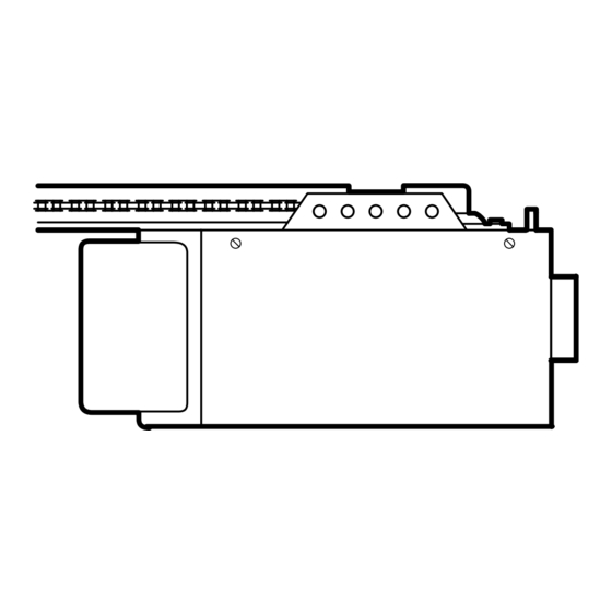
Page 38: Motor Unit Assembly Parts
Helical gear w/retainer and grease 41A2817 Drive/worm gear kit w/grease, Roll pins (2) 41B4245 Line cord 143D100 End panel (Series 2200C) 143D152 End panel (Series 4200C & 4200C-2) 175B88 Light socket 108D36 Lens (Series 2200C) 108D34 Lens (Series 4200C &... -
Page 39: Accessories
ACCESSORIES 953C SECURITY Multi-Function Remote Control: Includes visor clip. SECURITY Multi-Function 956C Mini Remote Control: With key ring and Velcro fastening strip. 945C Multi-Function Door Control Panel: Provides a Lock feature which prevents operation of garage door opener from portable remotes and a Light feature for constant light. -
Page 40: Warranty
CHAMBERLAIN GARAGE DOOR OPENER ONE-YEAR LIMITED WARRANTY The Chamberlain Group, Inc. (“Seller”) warrants to the first retail purchaser of this product, for the residence in which this product is originally installed, that it will be free from any defect in materials and/or workmanship for a period of one year from the date of purchase. - Page 41 L’étiquette du numéro de modèle est située sur une étiquette collée sur le panneau avant de votre ouvre-porte. 845 Larch Avenue Elmhurst, Illinois 60126-1196 www.chamberlaingroup.com ® Série 2200C – 1/3 HP ® n'est pas ®...
-
Page 42: Introduction
TABLE DES MATIÈRES Introduction Revue des symboles de sécurité et des mots de signalement...2 Préparation de votre porte de garage ...3 Outils nécessaires ...3 Planning ...4-5 Inventaire des boîtes d'emballage ...6 Inventaire des fixations...7 Sur le montage Assemblage des rails et pose du support de la poulie du câble ...8 Pose du chariot ...9 Fixation du rail en T au moteur ...9... -
Page 43: Préparation De Votre Porte De Garage
Préparation de votre porte de garage Avant de commencer : • Inactiver les serrures. • Retirer toute corde raccordée à la porte de garage. • Procéder au contrôle suivant pour s’assurer que la porte est bien équilibrée et qu’elle ne coince pas : 1. - Page 44 Planification Identifier le type et la hauteur de votre porte de garage. Examiner la région du garage pour noter si l’une des conditions ci-après s’applique à votre installation. Des matériaux supplémentaires peuvent être nécessaires. Il vous sera peut-être utile de vous reporter à cette page et aux illustrations qui l’accompagnent en procédant à...
- Page 45 Planification (suite) POSE DE PORTE RIGIDE • En règle générale, une porte rigide ne nécessite aucun renfort. Pour une porte légère, prière de se reporter aux informations ayant trait aux portes articulées à la 11 opération de montage. • En fonction de la construction de la porte, des fixations supplémentaires seront peut-être requises pour le support de la porte.
-
Page 46: Inventaire Des Boîtes D'emballage
Les pièces peuvent être coincées dans la mousse. Les fixations nécessaires à l’assemblage et au montage apparaissent sur la page suivante. Conserver la boîte et le matériel d’emballage jusqu’au terme du montage et du réglage. Série 4200C & 2200C (1) Série 4200C-2 (2) SECURITY Télécommande à un bouton Support de la poulie du câble... -
Page 47: Inventaire Des Fixations
Inventaire des fixations Séparer toutes les fixations et les regrouper comme illustré ci-après aux fins des opérations d’assemblage et de montage. Vis hexagonale de Vis à rondelle-frein de 5/16 de po-18x7/8 de po (3) 5/16 de po-1/2 po (2) (montées dans l'ouvre-porte) Tige filetée du chariot (1) Tire-fond de... -
Page 48: Assemblage Des Rails Et Pose Du Support De La Poulie Du Câble
MONTAGE - 1 OPÉRATION Assemblage des rails et pose du support de la poulie du câble Pour ne pas rencontrer de difficultés pendant la pose, ne faire fonctionner l'ouvre-porte de garage que lorsque cela est expressément indiqué. 1. Sur une surface plane, aligner les 4 sections de rail, exactement comme il est illustré. -
Page 49: Pose Du Chariot
MONTAGE - OPÉRATION Pose du chariot • Poser la tige filetée sur le chariot avec une rondelle- frein et des écrous, comme il est illustré. • Comme butée temporaire, introduire un tournevis dans le trou qui se trouve à l'avant du rail. •... - Page 50 MONTAGE - 4 OPÉRATION Pose de la chaîne et du câble et fixation du carter du pignon POSE DE LA CHAIINE ET DU CABLE 1. Tirer la boucle du câble et l'accrocher sur le chariot avec un des maillons de raccord que l'on trouvera dans le sachet des fixations.
-
Page 51: Tension De La Chaîne Et Du Cäble
MONTAGE - 5 OPÉRATION Tension de la chaîne et câble • Dévisser l’écrou intérieur de la tige filetée du chariot et éloigner la rondelle. • Pour tendre la chaîne, tourner l’écrou extérieur dans le sens illustré. ALORS QUE L’ON TOURNE L’ÉCROU, EMPÊCHER LA CHAÎNE DE VRILLER. -
Page 52: Déterminer L'emplacement Du Support De Linteau
POSE - 1 OPÉRATION Déterminer l'emplacement du support de linteau AVERTISSEMENT Pour prévenir d’éventuelles LÉSIONS GRAVES ou la MORT : • Le support de linteau DOIT être fixé DE MANIÈRE RIGIDE à la solive sur le linteau ou le plafond, sinon la porte de garage pourrait ne pas remonter au besoin. - Page 53 PORTE RIGIDE SANS GUIDES 1.La porte étant fermée, repérer et tracer l'axe vertical de la porte du garage et prolonger cette ligne sur le mur, au-dessus de la porte comme il est illustré. Si la hauteur au-dessus du plafond n'est pas suffisante, on pourra poser le support de linteau sur le plafond.
-
Page 54: Pose Du Support De Linteau
POSE - 2 OPÉRATION Pose du support de linteau Le support de linteau peut être fixé soit sur le mur au- dessus de la porte, soit sur le plafond. Suivre les instructions qui répondent le mieux aux besoins particuliers. Ne pas poser le support de linteau sur des plaques de placoplâtre. -
Page 55: Fixation Du Rail Sur Le Support De Linteau
Linteau Support de linteau Support de la poulie de câble Rail Porte de garage Moteur GRANDEUR RÉELLE DES FIXATIONS Axe de chape de 5/16 po x 2-3/4 po POSE - 3 OPÉRATION Fixation du rail sur le support de linteau •... -
Page 56: Positionnement De L'ouvre-Porte
POSE - 4 OPÉRATION Positionnement de l'ouvre-porte Suivre les instructions qui se rapportent à la porte du garage, en se rapportant aux illustrations. PORTE ARTICULÉE OU PORTE RIGIDE AVEC GUIDES Un 2x4 convient très bien pour obtenir l'espace qu'il faut entre la porte et le rail. -
Page 57: Accrochage De L'ouvre-Porte
POSE - 5 OPÉRATION Accrochage de l'ouvre-porte Les illustrations représentent deux poses type. La pose peut toutefois être différente. Les supports de suspension doivent être inclinés, (Figure 1), pour assurer un support rigide. Dans le cas d'un plafond fini, (Figure 2), fixer une cornière aux solives du plafond avant de poser l'ouvre-porte. -
Page 58: Pose De La Commande De Porte
POSE - 6 OPÉRATION Pose de la commande de porte Placez le contrôle de porte en vue de la porte à une hauteur minimum de 5 pieds hors d'atteinte des enfants en bas âge et à l'écart de toutes les pièces en mouvement de la porte et du matériel de la porte. -
Page 59: Pose De La Corde Et De La Poignée De Déclenchement D'urgence
• Pour déposer les diffuseurs, procéder à l'inverse de la pose. POSE DU DIFFUSEUR (SÉRIE 2200C) • Voir Figure 2. • Trouvez (et desserez à peu prés 1/8 po) les deux vis prés de la tête du panneau avant. -
Page 60: Exigences Électriques
POSE - 9 OPÉRATION Exigences électriques Pour éviter de rencontrer des difficultés pendant la pose, ne pas faire fonctionner l'ouvre-porte pour le moment. Afin de minimiser les risques de chocs électriques, le cordon d'alimentation de l'ouvre-porte de garage comporte une fiche à trois broches, dont une de mise à la terre. -
Page 61: Pose Du Système Protector
POSE - 10 OPÉRATION Pose du Système Protector Les détecteurs inverseurs de sécurité doivent être bien branchés et bien alignés avant que l'ouvre- porte de garage puisse fermer la porte. INFORMATIONS IMPORTANTES AU SUJET DU DÉTECTEUR INVERSEUR DE SÉCURITÉ Lorsqu’il est bien raccordé et aligné, le détecteur détecte un obstacle dans le parcours de son faisceau électronique. - Page 62 POSE DES SUPPORTS S’assurer que l’ouvre-porte est hors tension. Poser et aligner les supports de manière à ce que les détecteurs se fassent face l’un l’autre à travers la porte du garage, le faisceau n’étant pas à une hauteur de plus de 6 po au-dessus du sol.
- Page 63 MONTAGE ET CÂBLAGE DES DÉTECTEURS INVERSEURS • Faire glisser un boulon à tête bombée et collet carré de 1/4 po-20x1/2 po dans la fente de chaque capteur. Utiliser des écrous à oreilles pour fixer les détecteurs aux supports, avec les diffuseurs dirigés l’un vers l’autre à...
-
Page 64: Fixation Du Support De La Porte
POSE - 11 OPÉRATION Fixation du support de porte Suivre les instructions qui correspondent au type de porte, comme il est illustré ci-dessous ou à la page suivante. Un renfort horizontal doit être suffisamment long pour être fixé à deux ou trois supports verticaux. Un renfort vertical doit couvrir la hauteur du panneau supérieur. - Page 65 PORTES RIGIDES Prière de lire et de suivre les avertissements et les instructions de renforcements à la page précédente. Ils s’appliquent également aux portes rigides. • Centrer le support de porte sur le dessus de la porte, en l'alignant avec le support de linteau, comme il est illustré.
-
Page 66: Fixation De La Biellette De La Porte Au Chariot
POSE - 12 OPÉRATION Fixation de la biellette au chariot Suivre uniquement les instructions se reportant au type de porte, comme il est illustré ci-dessous et à la page suivante. PORTE ARTICULÉE SEULEMENT • S'assurer que la porte du garage est complètement fermée. - Page 67 POUR TOUTES LES PORTES RIGIDES 1. Assemblage des biellettes : • Assembler les biellettes droite et courbée à leur plus grande longueur (2 ou 3 trous se chevauchant). • La porte étant fermée, raccorder la biellette droite au support de la porte à l'aide d'un axe de chape de 5/16 po x 1-1/4 po.
-
Page 68: Réglage Des Courses
RÉGLAGES - 1 OPÉRATION Réglage des courses d’ouverture et de fermeture Le réglage de ces courses fixe les points où la porte s'arrêtera lors de son ouverture ou de sa fermeture. Pour faire fonctionner l'ouvre-porte, appuyer sur le bouton-poussoir de la commande de porte. Faire faire un cycle complet à... -
Page 69: Réglage De La Force
RÉGLAGES - 2 OPÉRATION Réglage de la force Les commandes de réglage de la force sont situées sur le panneau arrière du moteur. Elles servent à régler la puissance du courant nécessaire à l'ouverture et à la fermeture de la porte. Si la force est réglée trop faible, la porte aura tendance à... - Page 70 RÉGLAGES - 3 OPÉRATION Essai du système d’inversion de sécurité CONTRÔLE : • La porte étant entièrement ouverte, mettre un 2x4 à plat sur le plancher, au centre et sous la porte de garage. • Fermer la porte. La porte doit remonter dès qu'elle touche le morceau de bois.
-
Page 71: Utilisation De Votre Ouvre-Porte De Garage
FONCTIONNEMENT IMPORTANTES CONSIGNES DE SÉCURITÉ Pour réduire le risque de blessures graves ou de mort : 1. LIRE ET SUIVRE TOUS LES AVERTISSEMENTS ET INSTRUCTIONS. 2. TOUJOURS garder les télécommandes hors de la portée des enfants. Ne JAMAIS laisser les enfants faire fonctionner les télécommandes ou les boutons-poussoirs de la commande de porte ou jouer avec ceux-ci. -
Page 72: Utilisation De La Commande De Porte
Utilisation de la commande de porte à montage mural BOUTON ÉCLAIRÉ DE LA COMMANDE DE PORTE Appuyer sur la barre pour ouvrir ou fermer la porte. Appuyer à nouveau sur la barre pour faire remonter la porte lors du cycle de fermeture ou pour arrêter la porte pendant le cycle d'ouverture. -
Page 73: Entretien De Votre Ouvre-Porte De Garage
Entretien de l’ouvre-porte de garage RÉGLAGES DE COURSE ET DE FORCE : Les conditions climatiques risquent de causer de petites modifications dans le fonctionnement de la porte qui devra alors être réglée, en particulier après la première année d’utilisation. Se reporter aux pages 28 et 29 pour les réglages des courses d’ouverture et de fermeture et de la force. - Page 74 Défauts de fonctionnement (suite) 6. La porte s’ouvre et se ferme toute seule: • S’assurer que tous les boutons-poussoirs de la télécommande sont à la position d’arrêt. • Débrancher le fil de sonnerie des bornes de la commande de porte et faire fonctionner la télécommande seulement.
-
Page 75: Pour Ajouter Une Télécommande À Main
PROGRAMMATION Votre ouvre-porte de garage a été programmé en usine de manière à fonctionner avec votre télécommande à main. La porte s’ouvrira et se fermera lorsque vous appuierez sur le gros bouton-poussoir. Vous trouverez ci-après des instructions pour programmer votre ouvre-porte en vue du fonctionnement avec d’autres télécommandes Security . -
Page 76: Pour Ajouter Ou Modifier Un Nip D'entrée Sans Clé
Pour ajouter ou modifier un NIP d’entrée sans clé REMARQUE : Votre nouvelle entrée sans clé doit être programmée de manière à faire fonctionner votre ouvre-porte de garage. UTILISATION DU BOUTON « LEARN » 1. Enfoncer et tenir le bouton LEARN sur le moteur. -
Page 77: Pièces D'assemblage Des Rails
PIÈCES DE RECHANGE Pièces d’assemblage des rails Pièces pour la pose RÉF. N° DE RÉF. PIÈCE 41A4166 41A5056-8 10A20 29B137 41A2828 217A238 41A4353 41A5047 178B35 178B34 12B350 41A5034 41A5266-1 41A3475-17 114A2276 N° DE PIÈCE DÉSIGNATION 4A1008 Maillon de raccord 41A3489 Chariot complet 183B112 Support (chacune) - Page 78 Cordon électrique 143D100 Panneau d’extrémité (Série 2200C) 143D152 Panneau d’extrémité (Série 4200C & 4200C-2) 175B88 Douille d'ampoule 108D36 Diffuseur (Série 2200C) 108D34 Diffuseur (Série 4200C & 4200C-2) 30B363 Condensateur - 1/2HP 30B387 Condensateur - 1/3HP 12A373 Support de condensateur 41A3150...
-
Page 79: Accessoires
ACCESSOIRES 953C SECURITY Télécommande à trois boutons standard : Y compris pince de pare-soleil. SECURITY Mini-télécommande 956C à multi-fonction : Y compris pince de pare-soleil. 945C Panneau commande de porte à trois boutons : La caractéristique de verrouillage est conçue pour empêcher le fonctionnement de la porte à... -
Page 80: Garantie
Série 4200C & 4200C-2: Le moteur est garanti exempt de vices de matières et/ou de fabrication pendant 72 mois (6 ans) à partir de la date d'achat. Série 2200C: Le moteur est garanti exempt de vices de matières et/ou de fabrication pendant 48 mois (4 ans) à partir de la date d'achat.