Advertisement
Quick Links
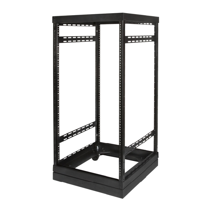
SR-CUSTOM Series
Floor Standing AV Rack System
Package Contents
A. 1x Top plate
B. 4x Rack pillars
C. 4x Side bars
D. 1x Base assembly
4x Casters
•
4x Leveling feet
•
E. Assembly hardware (not shown)
•
40x Rack assembly screws
•
16x Side bar screws
F. 3mm Hex driver bit
Key Features
•
Easy assembly
•
Counter-sunk assembly screws for clean
appearance
•
Locking pillars for extra stability and rigidity
Concealed caster wheels
•
•
Adjustable leveling feet
•
Built in top ventilation mounting
•
1000 lb. maximum load
•
Optional locking doors and side panels
Optional Accessories (sold separately)
•
Side Panels (SR-CUST-SP-XXU-XXIN)
•
Window Door (SR-CUST-DOOR-XXU-GLS)
•
Solid Door (SR-CUST-DOOR-XXU-SLD)
•
Integrated Cooling (SR-FANBRACKET-2/4)
Assembly Recommendations
•
The included hex driver should only be used with
torque-adjustable drills.
•
It is recommended to hand tighten the assembly
screws to final torque to avoid snapping screws.
G
A
B
C
D
To ground cabinet, connect the ground wire to
the field wiring ground terminal on the bottom
panel first. To ground, use UL Listed closed loop
connectors with minimum 12 AWG wire 1/4"
zinc plated steel or stainless steel internal tooth
washer, and an M6 nut.
CAUTION!
When loading equipment into cabinet,
ensure that leveling feet are adjusted
correctly and they come in contact with the
supporting surface. Always load heavier
equipment at the bottom of the rack with a
minimum of 200 lbs into lower U spaces.
Equipment cabinets are intended to house
or mount certified equipment that is provided
with its own fire and electrical enclosure.
© 2020 Wirepath Home Systems, LLC
Advertisement

Related Manuals for Strong SR-CUSTOM Series


Summary of Contents for Strong SR-CUSTOM Series
- Page 1 SR-CUSTOM Series Floor Standing AV Rack System Package Contents A. 1x Top plate B. 4x Rack pillars C. 4x Side bars D. 1x Base assembly 4x Casters • 4x Leveling feet • E. Assembly hardware (not shown) • 40x Rack assembly screws •...
- Page 2 Attach the pillars to the base. Attach the top to the pillars. Optional: Adjust the leveling feet. Attach the side bars. Note: The side bars are not required for structural support Note: Lowering the leveling feet restricts the steering and can be mounted at any height. (Two of four included rotation of the casters.
- Page 3 Optional: Install front and rear doors Note: The door may be installed for left or right-hand Note: Before installing the door, position the hinge swing. Hinge brackets are held on by 2 of the 3 assembly bushings in the holes on the top and bottom brackets screws at each corner.
- Page 4 This warranty shall not apply to products that have been abused, modified, or disassembled. Products to be repaired under this warranty must be returned to Strong or a designated service center with prior notification and an assigned return authorization number (RA).