Table of Contents
Advertisement
Quick Links
Advertisement
Table of Contents

Related Manuals for ADTRAN Cable T1 ESF CSU ACE


Summary of Contents for ADTRAN Cable T1 ESF CSU ACE
-
Page 1: User Manual
T1 ESF CSU ACE User Manual 1204025L1 T1 ESF CSU ACE 61204025L1-1B September 2004... - Page 2 To the Holder of the Manual The contents of this manual are current as of the date of publication. ADTRAN reserves the right to change the contents without prior notice. In no event will ADTRAN be liable for any special, incidental, or consequential damages or for commercial losses even if ADTRAN has been advised thereof as a result of issue of this publication.
- Page 3 4. Use only the power cord, power supply, and/or batteries indicated in the manual. Do not dispose of batteries in a fire. They may explode. Check with local codes for special disposal instructions. Save These Important Safety Instructions 61204025L1-1B © 2004 ADTRAN, Inc.
- Page 4 End user/customer will be responsible for filing an affidavit with the local exchange carrier when connecting unprotected customer premise equipment (CPE) to 1.544 Mbps or subrate digital services. Until such time as subrate digital terminal equipment is registered for voice applications, the affidavit requirement for subrate services is waived. © 2004 ADTRAN, Inc. 61204025L1-1B...
- Page 5 I agree to provide ______________________ (telco’s name) with proper documentation to demonstrate compliance with the information as provided in the preceding paragraph, if so requested. _________________________________Signature _________________________________Title _________________________________ Date Transcribed and sworn to before me This ________ day of _______________, _______ _________________________________ Notary Public My commission expires: _________________________________ 61204025L1-1B © 2004 ADTRAN, Inc.
- Page 6 Advance notification and the opportunity to maintain uninterrupted service are given. 4. If experiencing difficulty with this equipment, please contact ADTRAN for repair and warranty information. The telephone company may require this equipment to be disconnected from the network until the problem is corrected or it is certain the equipment is not malfunctioning.
-
Page 7: Federal Communications Commission Radio Frequency Interference Statement
Shielded cables must be used with this unit to ensure compliance with Class A FCC limits. Changes or modifications to this unit not expressly approved by the party responsible for compliance could void the user’s authority to operate the equipment. 61204025L1-1B © 2004 ADTRAN, Inc. - Page 8 Department of Communications. Cet appareil numérique respecte les limites de bruits radioelectriques applicables aux appareils numériques de Class A prescrites dans la norme sur le materiel brouilleur: “Appareils Numériques,” NMB-003 edictee par le ministre des Communications. © 2004 ADTRAN, Inc. 61204025L1-1B...
- Page 9 Warranty and Customer Service ADTRAN will repair and return this product within 5 years from the date of shipment if it does not meet its published specifications or fails while in service. For detailed warranty, repair, and return information refer to the ADTRAN Equipment Warranty and Repair and Return Policy Procedure.
- Page 10 Customer Service, Product Support Information, and Training ADTRAN will repair and return this product if within 5 years from the date of shipment the product does not meet its published specification or the product fails while in service. A return material authorization (RMA) is required prior to returning equipment to ADTRAN. For service, RMA requests, training, or more information, use the contact information given below.
- Page 11 Technical Support Installation and Maintenance Support The ADTRAN Custom Extended Services (ACES) program offers multiple types and levels of installation and maintenance services which allow you to choose the kind of assistance you need. This support is available at: http://www.adtran.com/aces...
- Page 12 © 2004 ADTRAN, Inc. 61204025L1-1B...
-
Page 13: Table Of Contents
T1 ESF CSU ACE Overview ...19 Features ...21 Interface Features ...22 Four Methods of Control ...23 Front Panel ...23 ADTRAN PC Program ...23 SNMP ...23 ASCII Terminal ...23 T1 ESF CSU ACE Testing ...24 Self Test ...24 Loopback Tests ...25 Network Loopbacks ...25... - Page 14 1)STATUS ...38 2)CONFIG ...42 3)UTIL ...46 4)TEST ...48 Appendix A Pinouts ...51 Appendix B Specification Summary ...53 Specifications and Features ...53 Appendix C Acronyms/Abbreviations ...55 Appendix D Glossary ...59 T1 ESF CSU ACE User Manual © 2004 ADTRAN, Inc. 61204025L1-1C...
- Page 15 Figure 3-17. Utility Menu Tree ... 47 Figure 3-18. Re-initialize Unit/Address Screen ... 47 Figure 3-19. Test Menu Tree ... 48 Figure 3-20. Local Loopback Test Screen ... 49 Figure 3-21. Self Test Result Screen ... 50 61204025L1-1B © 2004 ADTRAN, Inc.
- Page 16 List of Figures T1 ESF CSU ACE User Manual © 2004 ADTRAN, Inc. 61204025L1-1B...
-
Page 17: List Of Tables
List of Tables Table A-1. RJ-48C Connector Pin Assignments... 51 Table A-2. EIA-232 Connector Pin Assignments... 51 61204025L1-1B © 2004 ADTRAN, Inc. - Page 18 List of Tables T1 ESF CSU ACE User Manual © 2004 ADTRAN, Inc. 61204025L1-1B...
-
Page 19: Chapter 1 Introduction
T1 line. The T1 ESF CSU ACE (extended superframe channel service unit advanced communication equipment) provides the required interface between the CPE (such as DSUs, channel banks, T1 multiplexers, and PBXs) and telco or private T1 facilities. Figure 1-1 depicts a typical application. 61204025L1-1B © 2004 ADTRAN, Inc... -
Page 20: Figure 1-1. T1 Esf Csu Ace Application
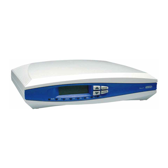
Figure 1-2 shows the front of the T1 ESF CSU ACE, and Figure 1-3 shows the back of the T1 ESF CSU ACE. Figure 1-4 shows the jack signal directions. Figure 1-2. T1 ESF CSU ACE Front View © 2004 ADTRAN, Inc 61204025L1-1B... -
Page 21: Features
Can configure a modem so that it does not have to be configured before installation. • Backs up configuration data in EEPROM. 61204025L1-1B Figure 1-3. T1 ESF CSU Rear View Figure 1-4. Jack Signal Directions © 2004 ADTRAN, Inc Chapter 1. Introduction... -
Page 22: Interface Features
EIA-232 input from a PC or a modem for control of the T1 ESF CSU ACE • Up to 9600 baud operation • Acts as input for PC or proxy agent control • VT100 terminal interface T1 ESF CSU ACE User Manual © 2004 ADTRAN, Inc 61204025L1-1B... -
Page 23: Four Methods Of Control
ACE directly or through a modem, in the same manner as the T-Watch PC programs. ASCII Terminal The ADTRAN T1 ESF CSU ACE recognizes an escape sequence that puts the unit into the ASCII terminal mode. After receiving the sequence, the T1 ESF CSU ACE sends front panel information to the terminal. -
Page 24: T1 Esf Csu Ace Testing
These run during normal operation to confirm continued correct functioning. The background tests include the standard background network performance monitoring as required by ANSI T1.403 and AT&T 54016, for which the results are stored. T1 ESF CSU ACE User Manual © 2004 ADTRAN, Inc 61204025L1-1B... -
Page 25: Loopback Tests
EIA-232 control port, or T-Watch commands. The DTE (or external test equipment) must provide any test pattern in order to check the DTE interface. See Figure 1-6. 61204025L1-1B Figure 1-5. Network Loopback Tests Figure 1-6. DTE Interface Loopback © 2004 ADTRAN, Inc Chapter 1. Introduction... -
Page 26: Pattern Generation
Three applications are shown in this section. Figure 1-7 on page 27 shows a general data application; Figure 1-8 on page 28 shows a general voice application; and Figure 1-9 on page 28 shows a channel bank application. © 2004 ADTRAN, Inc 61204025L1-1B... -
Page 27: Figure 1-7. General Data Application
T1 ESF CSU ACE User Manual Chapter 1. Introduction Figure 1-7. General Data Application 61204025L1-1B © 2004 ADTRAN, Inc... -
Page 28: Figure 1-8. General Voice Application
Chapter 1. Introduction Figure 1-8. General Voice Application DSX-1 Figure 1-9. Channel Bank Application © 2004 ADTRAN, Inc T1 ESF CSU ACE User Manual DSX-1 61204025L1-1B... -
Page 29: Chapter 2 Installation
Carefully inspect the T1 ESF CSU ACE for any shipping damages. If damage is suspected, file a claim immediately with the carrier and then contact ADTRAN Technical Support. If possible, keep the original shipping container to ship the T1 ESF CSU ACE back for repair or to verify damage during shipment. -
Page 30: Wiring
The EIA-232 connector is used to connect the T1 ESF CSU ACE to a proxy agent, T-Watch, an ASCII terminal, or a modem. See Table A-2 on page 51 for the connector pin assignments. Connector Type = Female DB-9 T1 ESF CSU ACE User Manual Method 2 © 2004 ADTRAN, Inc 61204025L1-1B... -
Page 31: Power-Up Testing And Initialization
Self Test Upon a power-up or self test, the LCD displays ADTRAN T1 ESF CSU ACE INITIALIZING and the LEDs illuminate momentarily. When the self test is completed with no failures detected, the LCD momentarily displays ALL TESTS PASSED. If a failure is detected, it is displayed in the LCD window. - Page 32 Chapter 2. Installation T1 ESF CSU ACE User Manual © 2004 ADTRAN, Inc 61204025L1-1B...
-
Page 33: Chapter 3 Operation
T-Watch. This chapter describes configuration from the front panel. FRONT PANEL OPERATION The T1 ESF CSU ACE front panel operating functions are shown in Figure 3-1 and defined in this section. Figure 3-1. T1 ESF CSU ACE FRONT PANEL 61204025L1-1B © 2004 ADTRAN, Inc... -
Page 34: General Front Panel Menu Operation
The cursor is on the first field. If there are more than two menu fields, a down arrow is visible on the lower right corner. See Figure 3-3. Figure 3-3. Menu with Additional Item(s) Not Shown T1 ESF CSU ACE User Manual © 2004 ADTRAN, Inc 61204025L1-1B... -
Page 35: Selecting A Submenu Item
ENTER after making a data change, the original data value is restored and the cursor returns to the submenu field. 61204025L1-1B Figure 3-5. Editing a Data Field ENTER © 2004 ADTRAN, Inc Chapter 3. Operation to set the value. The unit now is set CANCEL... -
Page 36: View Display Only Data Fields
Figure 3-6. The Four Opening Menus Figure 3-7 on page 37 shows the complete menu tree. Figure 3-8 on page 38 is a limited overview. Following this figure is a detailed description of each menu item, presented in menu order. © 2004 ADTRAN, Inc 61204025L1-1B... -
Page 37: Figure 3-7. T1 Esf Csu Ace Menu Tree
2)SHELF SNMP ID: 7)REMOTE T-WATCH 3)SHELF SLOT: 1)LOCAL LOOPBACK 2)REM LB 3)TEST PATTERN 4)RUN SELFTEST © 2004 ADTRAN, Inc Chapter 3. Operation RESET PERF CNTRS CLEAR HISTORY LOSS OF SIGNAL AIS ALARM OUT OF FRAME YELLOW ALARM... -
Page 38: Detailed Menu Operation
2)UNIT MAIN MENU 3)TERMINAL (T1) 3)UTIL 4)TEST 1)LOCAL LOOPBK: 2)REM LB: 3)TEST PATTERN: 4)RUN SELFTEST © 2004 ADTRAN, Inc T1 ESF CSU ACE User Manual 1)NI PERF RPTS 2)NI ERR/ALM 3)NI HISTORY 4)T1 ERR/ALM 5)T1 HISTORY 1)SOFTWARE REV 2)REINIT UNIT... -
Page 39: Figure 3-9. Status Menu Tree
RED ALARM CODE VIOLATIONS BIPOLAR VIOLATIONS FRAME BIT ERRORS 4)T1 ERR ALM* 5)T1 HISTORY** Figure 3-9. Status Menu Tree © 2004 ADTRAN, Inc Chapter 3. Operation LOSS OF SIGNAL AIS ALARM OUT OF FRAME YELLOW ALARM RED ALARM CODE VIOLATIONS... -
Page 40: Figure 3-10. First Menu Of Ni Perf Rpts Menu
Since only the user’s copy of performance data is cleared by the T1 ESF CSU ACE, the data displayed here might be different from the data being sent to the network as maintenance message data. Data Values © 2004 ADTRAN, Inc T1 ESF CSU ACE User Manual 61204025L1-1B... -
Page 41: Figure 3-12. First Current Ni Errors/Alarms Screen
(CRC) errors in ESF or BPVs and frame bit errors in SF were received at BPVs in SF or ESF at NI Frame bits received incorrectly at NI Figure 3-13. Clear History Screen © 2004 ADTRAN, Inc Chapter 3. Operation... -
Page 42: Config
T1 ESF CSU ACE. There are nine submenu items that include setting the format and the line build out (LBO). 1)NETWORK (NI) 2)UNIT 3)TERMINAL (T1) Figure 3-14. Configuration Menu Tree Figure 3-15. Network (NI) Submenu © 2004 ADTRAN, Inc T1 ESF CSU ACE User Manual 1)FORMAT 2)CODE 3)YEL ALRM 4)XMIT PRM 5)KEEP ALIVE... - Page 43 ESF Format.) The factory default is OFF. 5)KEEP ALIVE Selects framed or unframed keep alive signal to be transmitted from NI when TI is in red alarm. The factory default is UNFRAMED. FRAMED UNFRAMED 61204025L1-1B © 2004 ADTRAN, Inc Chapter 3. Operation...
- Page 44 (1-24). The factory default is 1. 11) RBS END When robbed-bit signaling is enabled, enter the last DS0 in which robbed-bit signaling will occur (1- 24). The factory default is 24. T1 ESF CSU ACE User Manual © 2004 ADTRAN, Inc 61204025L1-1B...
-
Page 45: Figure 3-16. First 2)Unit Submenu Screen
2)OUTPUT - Selects whether the alarm traps (if enabled) are sent directly, or whether the tele- phone number stored in the T1 ESF CSU ACE should be dialed first (industry-standard AT dial command sent to modem). The factory default is DIRECT. DIRECT DIAL 61204025L1-1B © 2004 ADTRAN, Inc Chapter 3. Operation DISABLED. -
Page 46: Util
Use the Utility menu to view and set system parameters. See Figure 3-17. This includes setting the time and date and resetting all parameters to factory values or to re-initialize the unit. This menu is also used to view the unit’s software revision and ID setting. T1 ESF CSU ACE User Manual © 2004 ADTRAN, Inc 61204025L1-1B... -
Page 47: Figure 3-17. Utility Menu Tree
Use this submenu to display the current software revision level. This information is required when requesting assistance from ADTRAN Customer Service or when updates are needed. The top line gives the revision of interest. The bottom line displays information of use to ADTRAN only. Follow standard operating procedures to access the 3)UTIL menu items. -
Page 48: Test
NO PATTERN ALL ZEROS 3)TEST PATTERN 1:8 ALL DS0s ALL ONES 4)RUN SELFTEST Figure 3-19. Test Menu Tree © 2004 ADTRAN, Inc T1 ESF CSU ACE User Manual NO LOOPBACK AT&T INBAND LLB ANSI FDL LLB AT&T FDL PLB 61204025L1-1B... -
Page 49: Figure 3-20. Local Loopback Test Screen
Excessive errors on the T1 line can cause this failure. The FDL loopbacks fail if the FDL is not intact from one end point to the other. FDL loopbacks are valid only in the ESF framing mode. 61204025L1-1B maintenance messages on the FDL. © 2004 ADTRAN, Inc Chapter 3. Operation... -
Page 50: Figure 3-21. Self Test Result Screen
Upon invoking the command, the LCD displays INITIALIZING and test failures are displayed in the LCD window. If a failure is detected, note the failure prior to contacting ADTRAN technical support. The execution of a self test disrupts normal data flow and prevents remote communication until the self test is completed (approximately five seconds). -
Page 51: Appendix A Pinouts
Not used Not used Name Data from DTE to CSU Data from CSU to DTE Signal ground © 2004 ADTRAN, Inc Transmit data (from CSU to DTE) Transmit data (from CSU to DTE) Not used Receive data (from... - Page 52 Appendix A. Pinouts T1 ESF CSU ACE User Manual © 2004 ADTRAN, Inc 61204025L1-1B...
-
Page 53: Appendix B Specification Summary
DSX-1 up to 655 feet of 22-gauge ADAM cable Monitor and Configuration Access • Front panel keypad and display • EIA-232 control port • T-Watch over FDL (ESF only) Diagnostics • Self Test • Local Loopbacks • Remote Loopbacks • Test Patterns 61204025L1-1B © 2004 ADTRAN, Inc... - Page 54 Dimensions: 1.75”H x 6.25”D x 9.25”W • Weight: 1 lb. • Power: -12 VDC @ 250 mA; 115 VAC @ 60 mA (Provided wall mount supply) • MTBF: 784,314 hours • CLEI: NCT1CD9BAA T1 ESF CSU ACE User Manual © 2004 ADTRAN, Inc 61204025L1-1B...
-
Page 55: Appendix C Acronyms/Abbreviations
DSAP directory scope analysis program data set ready data service unit data terminal equipment data terminal ready facility data link FECN forward explicit congestion notification front end processor FIFO first in first out 61204025L1-1C © 2004 ADTRAN, Inc... - Page 56 SDLC synchronous data link control SLIP serial line internet protocol T1 ESF CSU ACE User Manual © 2004 ADTRAN, Inc 61204025L1-1C...
- Page 57 SW56 switched 56 sync synchronous transmit data data terminal ready transmit user-to-network interface vertical redundancy check wide area network exchange identification XMIT transmit 61204025L1-1C Appendix C. Acronyms/Abbreviations © 2004 ADTRAN, Inc...
- Page 58 Appendix C. Acronyms/Abbreviations T1 ESF CSU ACE User Manual © 2004 ADTRAN, Inc 61204025L1-1C...
-
Page 59: Appendix D Glossary
(2) to provide a time base. customer premise equipment. All telecommunications terminal equipment located on the customer premises, including telephone sets, private branch exchanges (PBXs), data terminals, and customer-owned coin-operated telephones. 61204025L1-1B © 2004 ADTRAN, Inc... - Page 60 A device designed to transmit and receive digital data on digital transmission facilities. DSU loopback A telco initiated test which loops the DSU back to the telco and is used to test the DDS circuit as well as the DSU/CSU. © 2004 ADTRAN, Inc T1 ESF CSU ACE 61204025L1-1B...
- Page 61 A variable-length unit of data, in frame-relay format that is transmitted through a frame relay network as pure data. Contrast with packet. See also Q.922A. frame relay network A telecommunications network based on frame relay technology. Data is multiplexed. Contrast with packet switching network. 61204025L1-1B © 2004 ADTRAN, Inc Appendix D. Glossary...
- Page 62 Contrast with frame relay network. parameter A numerical code that controls an aspect of terminal and/or network operation. Parameters control such aspects as page size, data transmission speed, and timing options. © 2004 ADTRAN, Inc T1 ESF CSU ACE 61204025L1-1B...
- Page 63 PVC between two points. Data terminating equipment with a need form continuous communion use PVCs. See also DLCI. remote configuration A feature designed into ADTRAN DSU/CSU products that allow remote DSU/CSU to be configured from a local DSU/CSU or VT100 compatible terminal. router A device that supports LAN-to-LAN communications.
- Page 64 A communications line connecting two frame relay switches to each other. VT100 A non-intelligent terminal or terminal emulation mode used for asynchronous communications. Used to config- ure the T1 ESF CSU ACE. © 2004 ADTRAN, Inc T1 ESF CSU ACE 61204025L1-1B...
- Page 65 Index Numerics 1 in 8 pattern 26 ACCESS TYPE (REMOTE UNIT) 48 ADDRESS 47 ADTRAN PC program 23 ALARMS 45 all ones pattern 26 all zeroes pattern 26 applications 26 arrows, menus 34 ASCII terminal 23 BIT STUFFING 44 channel bank application 28...
- Page 66 26 testing 24 interface loopbacks 25 network loopbacks 25 self test 24 TI HISTORY 42 TRAPS 45 T-Watch 23 UNIT 45 UTIL 46 Utility menu 46 wiring 30 XMIT PRM 43 YEL ALRM 43 © 2004 ADTRAN, Inc. 61204025L1-1B...