Advertisement
Available languages
Available languages
Quick Links
®
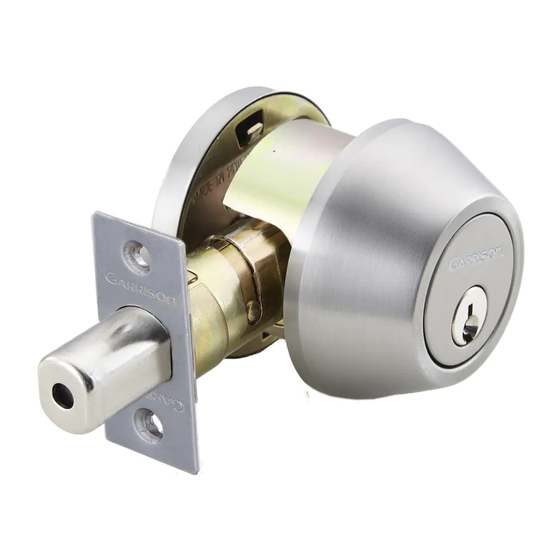
INSTRUCTIONS FOR INSTALLATION
OF DEADBOLT LOCK
For use on doors 1 3/8" to 1 3/4" (35 mm-45 mm) thick
model no.: 046-5631-0 & 046-5688-6 & 046-5690-8
Toll-free Number: 1-800-268-6591
IMPORTANT
: Please read this manual carefully
before installing this deadbolt lock and save it for reference.
Adjustable latch for 2 3/8" (60 mm) and 2 3/4" (70 mm) backset
Backset is a distance from door edge to centr of hole on
door face.
Some locks are supplied with adjustable latch which can fit
2 3/8" (60 mm) or 2 3/4" (70 mm) backset.
Follow the steps shown below to change backset.
Latch backset adjustment
Rotate
the latch case as
illustrated below,
for backset 2 3/4" (70 mm) or reverse
direction for 2 3/8" (60 mm).
180°
2 3/8" (60 mm)
To change latch face
Drive in installation
1. Use a flat-head screwdriver to separate
Make sure the round faceplate is
the faceplate from backplate.
properly aligned as illustrated and
2. Snap the selected faceplate onto backplate.
snap it to the latch case.
1. Mark the door with template
Select 2 3/8" or 2 3/4" (60 mm or 70 mm) backset
as desired and mark centre of hole on door face.
2. Drill holes
a. Drill 2" (51 mm) hole through door face, from both
sides to avoid wood splitting.
b. Drill 1" (25.4 mm) hole for latch
(refer to step 3d for drive-in latch).
3. Install latch
a
a. Insert latch in hole and keep it parallel
to door face.
Mark outline of face plate and remove
latch.
c
c. Insert latch and tighten screw.
4. Install strike
a
e
b
c
5. Install single cylinder exterior mechanism
2 3/4" (70 mm)
Drive-in latch
Mark 1" (25.4mm) hole at center of door edge.
b
b. Chisel 5/32" (4 mm) deep inside
traced outline or until face plate
is flush with door edge.
d
d. For drive in latch, drill 1" (25.4 mm)
hole and press latch until it is flush
with door edge.
a. Close the door so the latchbolt is against the door frame.
b. Measure one half of door thickness from door stop
and vertically mark center line of strike. Drill 1"
(25.4 mm) hole, 1" (25.4 mm) deep at intersection of
horizontal and vertical line of strike. Mark outline
using strike plate and chisel 5/64" (2 mm) deep for
strike.
c. Install strike and tighten screws.
Press cylinder side flush against door making certain the
tailpiece is properly positioned in latch crank. Tapped
holes in housing of exterior cylinder should be lined up
with screw holes. Key hole should be in down position.
TAILPIECE SHOULD BE HORIZONTALLY INSERTED INTO
LATCH CRANK.
Fold on dotted line and fit on door edge
45
40
35
1 3/4"
1 9/16"
1 3/8"
6. Install single cylinder interior mechanism
a
a. Slide turnpiece and interior rosette.
b. Insert both flanges into the hole on the door face.
b
Make sure the flanges stay in the hole when fastening
screws.
c
c. Insert machine screws through holes in cylinder and
tighten firmly.
7. Install exterior cylinder (double cylinder)
Press exterior cylinder flush against door.
Exterior tailpiece should be horizontally inserted
into latch crank first.
8. Install interior cylinder (double cylinder)
a. Press interior assembly flush against door, making certain
a
the tailpiece is properly positioned in latch crank.
Key hole should be in down position.
b. The interior tailpiece
blade.
b
c. Insert two screws through countersunk holes
c
in exterior cylinder and tighten firmly.
For 2 3/4" (70 mm) backset
For 2 3/8" (60 mm) backset
must be
inserted into the exterior
ø
2 1/8" 54 mm
(
)
G-LT-01
Advertisement

Related Manuals for Garrison 046-5688-6


Summary of Contents for Garrison 046-5688-6
- Page 1 Insert latch in hole and keep it parallel b. Chisel 5/32" (4 mm) deep inside b. Insert both flanges into the hole on the door face. model no.: 046-5631-0 & 046-5688-6 & 046-5690-8 to door face. traced outline or until face plate...
- Page 2 À l'aide d'un ciseau, enlevez une b. Assurez-vous que les deux petites ailes se trouvant sur la N° de modèle : 046-5631-0 & 046-5688-6 & 046-5690-8 ajustez-en la position de manière à ce couche de 4 mm (5/32 po) surface intérieure du tourniquet soient placées dans le trou...