Table of Contents
Advertisement
Advertisement
Table of Contents

Related Manuals for Alesis BRC


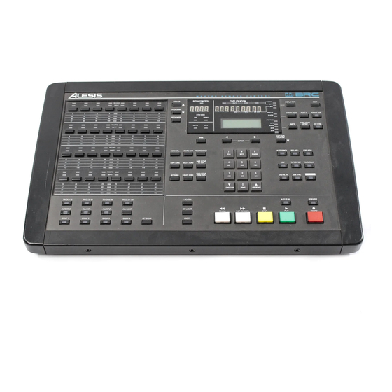
Summary of Contents for Alesis BRC
- Page 1 ALESIS Reference Manual...
-
Page 2: Table Of Contents
TABLE OF CONTENTS CHAPTER 1 - INTRODUCTION 1.0 ABOUT THE BRC...1 1.1 IMPORTANT NOTES ABOUT THIS MANUAL...4 1.2 OVERVIEW OF MAIN FUNCTIONS...4 1.2A Transport...4 1.2B Record/Monitor functions...5 1.2C Autolocation...5 1.2D Punching...5 1.2E Rehearsing...6 1.2F Digital Bus...6 1.3 “ENGAGED” VS “DISENGAGED” TAPES...7 1.4 BASIC OPERATION...7... - Page 3 3.1 FORMATTING TAPES...21 3.1A Additional Formatting Considerations...23 3.2 TRACK/RECORD MONITOR CONTROLS...24 3.2A Track Bank Select...24 3.2B Record Enables...25 3.2C Auto Input...25 3.2D All Input...25 3.2E All Safe...25 3.2F All Clear...26 3.2G Groups 1 Through 4...26 3.3 TRANSPORT CONTROLS...27 3.3A Play...27 3.3B Stop...27 3.3C Record...28 3.3D Rewind/Review...28...
- Page 4 4.6A Setting a Song...58 4.6B Naming a Song...60 4.6C Locate Song...60 4.6D Copy Song...61 4.6E Delete Song...62 4.7 DIGITAL BUSSING...63 4.7A Digital Input...63 4.7B Bouncing tracks...64 4.7C Using the AI-1...66 CHAPTER 5 - SYNCHRONIZATION, BACKUP AND MISC CONTROLS 5.0 SMPTE...69 5.0A SMPTE Formats...69 5.0B SMPTE Start Offset...69 5.0C External Sync...70...
-
Page 5: Chapter 1: Introduction
• Easy and familiar front panel controls. If you’ve ever used a large remote control for a multitrack tape recorder, then you probably already know how to use many of the functions on the BRC. Familiar controls like play, record, fast forward, rewind and the track select buttons perform the majority of functions you’ll need. - Page 6 (accepts composite video as well as black burst video inputs). • Storage of setups. To insure instant recall of the BRC’s settings, all setup information can be saved to the beginning of each ADAT tape for later retrieval. This information is known as the “table of contents”, or TOC.
-
Page 7: Hookup
• Meter bridge option. The RMB Remote Meter Bridge provides localized viewing of 32 channels of LED meters. It’s designed to mount on top of the BRC so that you can install your ADATs in a remote rack and control functions and view critical metering of the recording directly from one location. -
Page 8: Important Notes About This Manual
BRC Concepts and Applications . It will give you an understanding of how an ADAT/BRC system works, and the types of things you may expect. It explains why certain features are significant, and how to employ them in your recording routine. -
Page 9: C Autolocation
The BRC can control as many as 16 ADATs for up to 128 tracks. The track select section of the BRC provides access to 32 tracks at any time. Four buttons let you switch between TRACK 1–32, TRACK 33–64, TRACK 65–96 and TRACK 97–128. The button that has its LED lit will indicate which group of tracks is currently selected, as will the LEDs centered in the track select area, above. -
Page 10: E Rehearsing
For more information on Rehearse mode, see section 3.5. 1.2F Digital Bus With both the sync and digital bus cables connected, the BRC/ADAT system offers powerful digital track bouncing and copying functions. Let’s say you want to replace the chorus vocal on track 15 with the one you liked on track 2. -
Page 11: Engaged" Vs "Disengaged" Tapes
1.4A Displays There are three displays on the BRC. The top two are LED displays. The leftmost 3-digit LED display is used to indicate the PITCH CONTROL value (the range of this value is -300 through +100 cents). -
Page 12: B Display Type
1.4B Display Type It is important that you can reference tape positions in a way that you are comfortable with. That’s why we’ve designed the BRC to provide you with three different types of position indicators, so you can choose the one that best suits your needs. -
Page 13: D Led Indicators
the ABSOLUTE and RELATIVE LEDs will both be off. This is because when the Display Type is set to SMPTE, the counter is referenced to the SMPTE Start Offset (see section 5.0B) you have chosen to represent the start position of the current song (see section 4.6A). When the Display Type is set to BARS, the counter is referenced to bar 1, which is the start position of the current song. -
Page 14: F Cursor Buttons
• To exit from edit mode, press the EDIT button again (the EDIT LED will turn off) and the LCD will return to its state prior to entering edit mode. Pressing a toggle function button now will toggle that function on or off. Note: While in EDIT mode, only the currently selected function’s LED will be lit (along with the EDIT LED). -
Page 15: I Name Button
immediately change case. 1.4I NAME Button This button is used to edit the names of Songs and Cues. When you locate a Cue or Song, the name field in the display is not accessible using the cursor buttons. To edit a name, you must press the NAME button to select the name field. - Page 16 current tape location is copied into the currently display locate point (Locate 01–20) or Song Start (01–20). In Manual mode, when the COPY TAPE LOCATION button is pressed, the current tape location is copied to the manual locate point (Locate 00), and the display automatically goes to the Locate 00 page.
-
Page 17: Chapter 2: Hookup
CHAPTER 2: HOOKUP 2.0 POWER The BRC works with any AC voltage from 90 to 250 volts, 50 to 60 Hz. This eliminates the need for transformers or voltage switches. The BRC comes with a line cord for the destination to which the BRC is shipped. -
Page 18: B Adat Id (Identification) Numbers
So the first unit in the chain is assigned ID 1, the second is ID 2, and so on. Anytime an ADAT or the BRC is turned on or off, the ADATs will evaluate the situation and determine a master, which will in turn re-assign ID numbers. -
Page 19: Digital I/O
The numeric display on each slave ADAT unit will always show the NORMAL time (absolute or relative) location of each tape, regardless of the Display Type on the BRC (Normal, SMPTE or Bars; see section 1.4B). 2.2 DIGITAL I/O... -
Page 20: B Connecting The Ai-1
4. Finally, connect one end of a dual male, 9-pin D connector to the BRC’s sync out jack, and the other end to the AI-1’s sync in jack. The AI-1’s sync out jack must then be connected to the sync in jack of the first ADAT in your system;... -
Page 21: Smpte In/Out
This means you will not only need to connect the AI-1 to the digital bus (as described above), but you must also connect the AI- 1’s 48 KHz output to the BRC’s 48 KHz input, using a standard shielded BNC cable. -
Page 22: Midi In/Out
Any momentary single-pole/single-throw footswitch, normally open or normally closed, will work for the two footswitch functions. These should be plugged in prior to power-up so that the BRC can configure itself for the type of footswitch being used. 2.9 RACK-MOUNTING The four end blocks surrounding the BRC may be removed, if you TTL level square wave output. -
Page 23: Rollaround Stand
BRC. The figure below indicates the rack ears' locations and the screws that mount the end blocks. The front and back end blocks each use three 1" hexagonal screws, while the side end blocks use two 1-1/4"... -
Page 24: Chapter 3: Getting Ready To
ID numbers, the BRC’s display will count the number of ADATs it recognizes. For example: if you have four ADATs connected (32 tracks), the BRC will recognize each one at a time, and the display will look like this: ALESIS BRC... -
Page 25: Formatting Tapes
• If the first ADAT doesn’t have a tape in its drive, the Tape Location counter on the BRC will display "-- -- -- -- --" (the slave ADATs will display "-- --"). • The BRC will query each unit that contains an inserted tape as to its format status. - Page 26 Format Tape A ll If you wish to format all tapes, jump ahead to step 6a. If you wish to perform a selective format, continue to step 3. Press the Right Cursor button; The display will now look like this: Format Tape x x Disable …where XX is a tape machine number 1–16.
-
Page 27: A Additional Formatting Considerations
When performing a format extend, the ADAT begins "time- stamping" from the last valid time-stamp read from the formatted tape. This allows a partially formatted tape to have its format extended by entering format mode before the end of the previously formatted section. -
Page 28: Track/Record Monitor Controls
formatted part to the previously formatted part, there will be timing discontinuities and the audio will do unpleasant things. Also, during that transition the tape will be non-functional and you will not be able to record anything over it. When in doubt, either re-format the tape all the way to the end, or back up a bit and perform a format extend (see previous section) when you need to re-format over the transition zone. -
Page 29: B Record Enables
3.2B Record Enables To record enable a track, press the track’s associated record enable button. The track’s RECORD LED will flash to indicate the track is record-ready. If the transport is put into record mode (see section 3.3C), recording will begin, as indicated by the track’s RECORD LED being steadily lit. -
Page 30: F All Clear
previous state, and the record ready buttons will be functional again. 3.2F All Clear This switch is used to place all available tracks into a safe (non-record ready) mode with a single button press. It differs from the ALL SAFE button, in that it just clears all record ready tracks and does not disable track record ready buttons;... -
Page 31: A Play
The transport controls resemble those of a conventional tape recorder, although there are several extra features. The main transport functions have been designed to be easily and quickly recognizable by both sight and feel. 3.3A Play Press the PLAY button to play tape(s) (PLAY BUTTON is lit). The PLAY button by itself has no effect while playing or formatting. -
Page 32: C Record
LED will flash to indicate the tape is disengaged. • Disengage/engage the tape. While the Stop button is lit, press STOP again to disengage the tape (STOP button flashes). While the STOP button is flashing, press STOP again to engage the tape (STOP button is lit). -
Page 33: E Fast Forward/Cue
speed, and you can hear chunks of attenuated audio so you know where you are in the tape. The PLAY button will be lit, and the REWIND button will flash. This function is latching, which means that the system will remain in Review mode until a different transport button is pressed. -
Page 34: Rehearse
• When in Rehearse mode, nothing is saved to tape and therefore nothing is lost. Both the BRC and individual ADATs will flash their RECORD LED to indicate that recording is not taking place. When the REHEARSE button is pressed again, the LED will turn off to indicate that you are no longer in Rehearse mode and all further recording will be saved to tape. - Page 35 no track delays are in effect. To display/edit the currently stored track delay times: 1. Press the EDIT button (the EDIT button LED will go on to indicate you are in edit mode); 2. Press the TRACK DELAY button. All the record and input track LEDs will turn off and no longer reflect the current record/monitor status;...
- Page 36 8. Another track may be selected by pressing the corresponding track button and the above process repeated; 9. To clear all delays, press the ALL CLEAR button while in this page, or the following page; 10. To exit the delay time mode, exit the Edit mode by pressing the EDIT button (the EDIT LED will turn off) or press another toggle function button.
-
Page 37: Chapter 4 - Pitch, Autolocation And Punching Controls
CHAPTER 4: PITCH, AUTO-LOCATION AND PUNCHING CONTROLS 4.0 PITCH CONTROLS The BRC provides controls over pitch by adjusting the speed the tape is traveling. The Pitch controls include: PITCH MODE, PITCH UP, and PITCH DOWN buttons; the PITCH LED display; and the VARIABLE and FIXED LEDs. -
Page 38: Autolocation Controls
(“Intro”, “Verse A1”, etc.). You can tell the BRC to go to any one of these 20 locate points at any time. Additionally, a manual... -
Page 39: B Locate 0
beginning of each tape. 4.1B Locate 0 Press this button to have all slave ADATs rewind or fast forward to the 0 point location. Remember, this can be anywhere on the tape since pressing the RESET 0 button resets the tape counter to 00:00 (see section 4.1A). - Page 40 stored into locate point number 20. 2. If you want to edit the location address, press the Right Cursor button to move the cursor to the bottom of the display and use the Numeric Keypad to enter in the desired offset. The cursor will automatically advance through each pair of digits.
-
Page 41: D Naming A Locate Point
2. As you listen to the audio playing back, determine which sections of the song you want to create locate points for; 3. Rewind the tape again and engage Play mode; 4. As the tape plays through the song again, press the SET LOCATE button just as the tape reaches the first position you wish to set as a locate point;... -
Page 42: E Locating A Locate Point
change a characters case (lowercase or UPPERCASE); 5. Press the NAME button again when finished. Note: If the UP/DOWN buttons are pressed while the NAME button is held down, you can scroll through a default set of 16 pre-stored, generic names (such as “Verse A1”, “Chorus 2”, “Bridge”, etc.). You can edit these names, so that they represent the names you wish to use, such as “TurnArnd”, etc. -
Page 43: F Manual Locate
point’s address. The address is displayed according to the type of Display Type you have selected. If in NORMAL mode, the display will read 00:00:00 (minutes:seconds:frames). If in SMPTE mode, the display will read 00:00:00:00 (hours:minutes:seconds:frames); if in BARS mode, the display will read 01–01/00 (bars:beats:sub-beats). 2. -
Page 44: G Footswitch Controlled Autolocation
If you use a footswitch and its operation seems “reversed,” make sure it is firmly plugged into the jack, then turn the BRC off, wait a few seconds, and turn it on again. It will recalibrate itself to work with the footswitch. -
Page 45: H Using The Lrc Remote Control
In/Out jack, both located on the back of the BRC. Actually, you could connect two LRCs by using both jacks. Unlike when connected to an ADAT, the LRC is used as a remote control of the BRC. The LRC offers the following functions: •... -
Page 46: I Auto-Play
Whenever Loop Mode is turned on, the AUTO-PLAY button is automatically turned on as well (the AUTO-PLAY LED will go on) to indicate that when the Loop Start point is reached, the BRC will go back into play. This creates a true, endless “loop.” If you do not want the BRC to engage playback upon returning to the Loop Start point, you can turn off Auto-Play mode by pressing the AUTO-PLAY button. -
Page 47: A Setting Loop Points
• If LOOP is turned off after the BRC has reached the Loop End point and has begun rewinding to the Loop Start point, the transport will continue rewinding, without stopping at the Loop Start point. 4.2A Setting Loop Points To set the Loop Start and End points: 1. -
Page 48: B Automatic Looping
6. Press the LOOP button to toggle between Loop Start and End point displays. 7. If the desired loop point does not correspond to a stored locate point, the locate point’s tape address may be edited. Use the Cursor buttons to place the cursor under the desired field and use the Numeric Keypad, UP/DOWN buttons, or the COPY TAPE LOCATION button to enter the new values. -
Page 49: A Setting Auto-Punch Points
22 is that they make it easy to repeat a manual punch procedure as many times as you like. Just play the tape, go in and out of record, then turn on Auto-Punch; the BRC will punch in and out at precisely the same locations. - Page 50 1. Press the EDIT button (the EDIT button LED will go on to indicate you are in Edit mode); 2. Press the AUTO-PUNCH button; The display will show the Auto-Punch In point: In X X "LocNamxx" aa:bb:cc:dd …where XX is one of the stored locate numbers (01–20; 21 is auto- punch in, 22 is auto-punch out), LocNamxx is the locate point’s name, and aa:bb:cc:dd is its address.
-
Page 51: B Auto-Group Record
6. Pressing the AUTO-PUNCH button repeatedly will cause the display to toggle between the Punch-In and Punch-Out point displays, and a third display called Auto-Group record (see section 4.3B); 7. If the desired punch point does not correspond to a stored locate point, the locate point’s tape address may be edited. - Page 52 1. Access the third page of the AUTO-PUNCH function by pressing the AUTO-PUNCH button three times; The display will read: Auto-group rec channels by x x …where XX is the number of tracks you wish to record onto at the same time.
-
Page 53: C Footswitch Controlled Punching
• Tracks 5 and 6 record LEDs will be solid, while the LEDs of other record-enabled tracks will be flashing. 4th loop pass: • Auto-punch in and out occurs on track 7 and 8; • Tracks 7 and 8 record LEDs will be solid, while the LEDs of other record-enabled tracks will be flashing. -
Page 54: Pre-Roll & Post-Roll
If you use a footswitch and its operation seems “reversed,” make sure it is firmly plugged into the jack, then turn off the BRC, wait a few seconds, and turn the BRC on again. It will calibrate itself to work with the footswitch. -
Page 55: Tape Offset
a point beyond the locate point by the amount you specified, before rewinding. Both the Pre-Roll and Post-Roll times are set in the identical manner. To display and/or edit the Pre-Roll or Post-Roll Time: 1. Press the EDIT button (the EDIT button LED will go on to indicate you are in Edit mode);... -
Page 56: A Offsetting Adats
00:45:00 and Locate 02 is set to 01:20:00, then offsetting tape #2 from Locate 01 to Locate 02 means that when the BRC and all other non- offset tapes are at Locate 01’s position, tape #2 will be at Locate 02’s position. - Page 57 4. When the desired Offset Mode is selected, press the TAPE OFFSET button again; The second page will now be displayed, which will depend on the type of Offset mode you selected. • If the Offset mode = COUNTER OFFSET, then the following will be displayed: Offset Tape X X + aa:bb:cc...
- Page 58 8. Press the TAPE OFFSET button to turn it on (its LED will be lit). Note: If theTAPE OFFSET button is turned on and tape #1 is offset, the BRC's Tape Position display will change to reflect the offset amount. This is because the BRC always references its position to...
-
Page 59: B Continuous Play And Record
30 minutes. X and YY represent the second set of ADATs to be offset. They are automatically set depending on the number of ADATs connected to the BRC, and cannot be edited. 5. Use the UP/DOWN buttons or the Numeric Keypad to enter in the number of minutes you wish to offset the second set of ADATs by. - Page 60 • If there is only one ADAT connected, Continuous mode will not be selectable from the previous page (Offset mode). • If there are two ADATs connected, then X will be 2, and YY will not be displayed. This indicates that only the second unit will be offset.
-
Page 61: What Is A Song
ADATs. 4.6 WHAT IS A SONG? A Song is used to store certain parameters of the BRC, including: all 20 locate points and their names, Pre/Post-Roll times, Auto-Punch points, Loop points, Track Delays, Tape Offsets, Track Group buttons, Tempo Map, SMPTE format, SMPTE start offset, Gen Sync settings and Ext Sync settings. -
Page 62: A Setting A Song
Whenever you want to go to a specific location of a tape which is referenced to a song in the BRC, you can quickly get there by locating the song start using the LOCATE SONG button (see section 4.6C). -
Page 63: B Naming A Song
Note: Although the BARS Display Type is available for viewing (see section 1.4C), this cannot be edited in the Set Song display. This is because the song’s starting position is referenced only to the Normal tape position, and is always bar 1. When the Display type is set to SMPTE, the song start will default to 00:00:00:00. -
Page 64: C Locate Song
1. If the LCD display is not currently displaying the Set Song page, press the SET SONG button; 2. Press the NAME button to move the cursor to the first character in the song’s name; 3. Use the Cursor buttons to position the cursor beneath the character you wish to edit;... -
Page 65: D Copy Song
2. Press the LOCATE SONG button again to rewind or fast forward to the currently displayed song start address. The REW or FFW LED will flash depending on the direction of the search. Note: If the LOCATE SONG function is initiated while in record, recording will be stopped (punched out) before performing the locate. -
Page 66: E Delete Song
• When a song is copied, you are taken to the new song location that you copied to. So, if you selected song 1 and copied it to song 2, you would now be in song 2. The destination song's new locate points are equal to the original song's locate points, but offset by the difference in song start points (the offset is equal to the new song’s start point minus the original song’s start point). -
Page 67: Digital Bussing
Like all other locate changes, the song setup information is not actually deleted from the tape until you save the setup to tape, assuming you have already saved the setup at some point before deleting the song (see section 5.2). If you accidentally deleted a song, you could retrieve it by loading the setup data back from tape. -
Page 68: B Bouncing Tracks
DIGITAL I/O button LED will go on to indicate it is enabled). 4.7B Bouncing tracks The BRC makes it possible to copy tracks between ADATs without leaving the digital domain. The BRC assumes you have connected the digital bus correctly between all ADATs in the system (see section 2.2A). - Page 69 • If no source tracks are selected, the ADATs’ digital outputs will function as digital through connections. This allows for another digital audio device, such as the Alesis QuadraSynth, to be connected to the first ADAT’s digital input and thus recorded onto any ADAT connected to the digital bus.
-
Page 70: C Using The Ai-1
• When copying digital tracks, any track delays and machine offsets will be in effect. 4.7C Using the AI-1 The Alesis AI-1 is used to route up to two tracks at a time to other digital audio recording equipment from other manufacturers, including: multitrack digital recorders, hard disk recorders, digital effects devices, CD recorders and DAT machines. - Page 71 4. Press the DIGITAL I/O button again while the digital input display reads “AES/EBU” or “S/PDIF”; The display will show the following: Select tracks to output to AI-1 All the record and input track LEDs no longer reflect the record/monitor status. The TRACK INPUT LEDs will now reflect the current source tracks to be output to the AI-1.
- Page 72 KHz output to feed the BRC’s 48 KHz input (see section 2.2B). Note: The BRC’s 48KHz, SMPTE, and MIDI outputs will not be usable if the AI-1 provides no timing reference for the BRC. If the BRC is synchronizing to the 48KHz clock, SMPTE, or video sync, then all of the BRC’s outputs will be usable.
-
Page 73: Chapter 5: Synchronization, Backup And Misc Controls
Frame, 30 fps, and 30 fps Drop Frame. The LED(s) associated with the currently selected SMPTE format will be lit solid. When the BRC is set to synchronize to an external SMPTE source, the SMPTE format of the source will automatically be detected. -
Page 74: C External Sync
Clock Source. • Locate References include: Internal and SMPTE. These can be used to control the location of the BRC, without controlling the clock. • Clock Sources include: Internal, 48 KHz, Video and SMPTE. These control the sample clock rate of the ADAT/BRC system. - Page 75 Alesis AI-1, for example), it is important to synchronize the clock rate of the BRC to the incoming signal’s source. This can usually be done by feeding a 48 KHz clock source into the BRC (see sections 2.2B, 2.5 and 4.7C).
- Page 76 • Locate Reference = Internal; Clock Source = 48 KHz Input: This is the setup to be used when recording from an Alesis AI-1, where its 48 KHz clock signal is begin fed to the BRC. The BRC in this scenario will still use its own internal locate reference.
-
Page 77: D Generate Sync
SMPTE clock which remains constant. Initially, you would want the Locate Reference to be set to SMPTE in order for the BRC to first locate to the correct SMPTE position, and then change the Locate Reference to Internal, so that radical changes in the SMPTE position will be ignored. - Page 78 The GEN SYNC button is used to enable/disable the output of sync information. Sync information may be sent as SMPTE, MTC (MIDI Time-Code) or MIDI-Clock (see section 5.1). Pressing the GEN SYNC button will enable the output of sync information and its LED will light.
-
Page 79: Tempo Map
Note: The GEN SYNC button cannot be turned on until you have selected a synchronization type to output. If the GEN SYNC button is pressed when both the SMPTE and MIDI options are set to Off, the following display will briefly appear: Must select output type 5.1 TEMPO MAP... - Page 80 To create a tempo map: 1. Press the TEMPO MAP button; The display will show: Bar X XXX bb/nn xxx.x bpm …where XXXX (range: 0001 through 9999) is the bar at which the following time signature and tempo should start, bb/nn is the time signature (bb is the number of beats per measure ranging from 1 to 64, and nn is the type of note that equals a beat with valid values of 2, 4, 8 and 16), and xxx.x is the tempo (range: 40.0 through 240.0 beats per...
-
Page 81: B Displaying A Tempo Map
advance much faster due to the changes in tempo and time signature. Then, at about 00:35:00, the bars advance much slower. Figure 4 5.1B Displaying A Tempo Map To display existing tempo/time signature changes in the tempo map: 1. Press the TEMPO MAP button, to enter the Tempo Map display; 2. -
Page 82: D Erasing A Tempo Map
120 bpm tempo at bar 1, beat 1 (01–01/00). 5.2 BACKING UP All the settings of the BRC (the 20 songs, their 20 locate points and their names, tempo maps, pre-stored names list, pitch mode and value, punch points, loop points, pre/post-roll times, track delays,... -
Page 83: A Save Setup To Tape
5.3C. 5.2A Save Setup To Tape The SAVE SETUP TO TAPE button is used to save the BRC’s setup information to tape. This creates a TOC (table of contents) onto each tape. When this button is pressed, the display will read:... -
Page 84: B Load Setup From Tape
BRC function: Load from tape Completed • While the BRC is loading from tape, you can manually abort the process at any time by pressing STOP. Doing so will cause the display to look like this: Load aborted. -
Page 85: Midi/Util Button
MIDI storage device, such as the Alesis DataDisk, or recorded into a MIDI sequencer. To load this information back into the BRC, simply send it back into the MIDI-In port. The BRC will automatically go into receive mode the moment it begins to see the system-exclusive data. - Page 86 For example, if you send song #3 out as a system-exclusive dump, when you receive it back into the BRC it will be placed into song location 3. To initiate a system-exclusive data dump: 1.
-
Page 87: C Tape Status
• No Tape Present: You must insert a tape before recording can begin; • Not Responding: The BRC does not recognize a connected ADAT (check your cables and try again). To find out the status of an ADAT’s tape: 1. -
Page 88: D Lcd Display Contrast
5.3D LCD Display Contrast This function lets you adjust the contrast of the lower LCD display. The best setting will depend on the position of the BRC, and whether or not it has been rack-mounted. To adjust the LCD display contrast: 1. -
Page 89: E Group Buttons Enable/Disable
This function allows you to either enable or disable the track group buttons from being able to store and recall groups of record-enabled tracks. This is useful when you don’t want to worry about accidentally pressing one of the group buttons and losing the current record- enabled tracks. -
Page 90: G Software Version
5.3G Software Version If you cycle through all seven of the MIDI/UTIL button’s pages, you’ll come to the Software Version page. This will display the current software version the BRC is running under. The display will look like this: 7: Software Rev X.XX... -
Page 91: Chapter 6: Appendices
CHAPTER 6: APPENDICES 6.0 APPENDIX 1: SPECIFICATIONS Internal Memory Song Memory: Locate Points (per song): # of Preset Locate Names: Song Contents: Memory Backup: Remote/Sync Remote Control Connectors: Two 1/4" phone jacks (Transport User Remote Functions Accessible (and available on the LRC): Sync Connector: Sync Capability: Internal Sample Clock:... - Page 92 External Sync: General Front Panel Controls and Indicators: Rear Panel Controls and Connectors: Power Requirements: SMPTE (all formats), Video (composite or black-burst), and 48 KHz word clock Illuminating transport controls for Play, Stop, Fast Forward, Rewind, and Record. Numeric keypad (0-9, Up and Down).
- Page 93 Dimensions (H x W x D): Weight: Shipping Weight: Accessories Included: Optional Accessories: 10-5/8" x 17" x 4" (261.5 mm x 432 mm x 101 mm) 12 lbs (5.44 kg) 18 lbs (8.2 kg) IEC style AC power cord Owner’s Manual Concepts and Applications Handbook 30' 9-pin D connector Allen wrench...
-
Page 94: Maintenance/Service Information
6.1 APPENDIX 2: MAINTENANCE/SERVICE INFORMATION 6.1A Cleaning Disconnect the AC cord, then use a damp cloth to clean the BRC’s metal and plastic surfaces. 6.1B Maintenance Here are some tips for preventive maintenance. • Periodically check the AC cord for signs of fraying or damage. -
Page 95: Appendix 3 Trouble-Shooting
Check cables. Has the DIGITAL I/O button been turned on? Check your connections. Swap cables, then turn the BRC on again. Be sure all ADATs are powered on. Indicates that an ADAT’s error correction system is near the limits of its capacity.