Table of Contents
Advertisement
Quality Products
Since 1866!
Product information presented
here reflects conditions at time
of publication. Consult factory
regarding discrepancies or
inconsistencies.
Patent No. 7,203,976,
8,562,287
For missing, damaged parts or technical help, Call
ATTACH YOUR RECEIPT HERE
Purchase Date
STOP
1-800-742-5044
before returning product
For replacement pump, order N202RP
or see complete repair parts list on page 22
POWERFLUSH OPTIMA
1
MODEL #S1201/S1202/S1203
MODEL NO. ___________________
DATE CODE: __________________
DATE INSTALLED: _____________
P/N 018547 G
Advertisement
Table of Contents

Subscribe to Our Youtube Channel
Summary of Contents for Star PowerFlush Optima S1201
- Page 1 POWERFLUSH OPTIMA MODEL #S1201/S1202/S1203 Quality Products Since 1866! Product information presented here reflects conditions at time of publication. Consult factory regarding discrepancies or inconsistencies. Patent No. 7,203,976, 8,562,287 STOP For missing, damaged parts or technical help, Call 1-800-742-5044 before returning product For replacement pump, order N202RP or see complete repair parts list on page 22 ATTACH YOUR RECEIPT HERE...
-
Page 2: Table Of Contents
TABLE OF CONTENTS Safety Information ........2 Exposed Grinder/Tank Installation ..11 Package Contents ........4 Hidden Grinder/Tank Installation ....12 Specifications ...........4 Piping............13 Preparation ..........4 Toilet Installation ........15 General Pump Uses .........5 Adding Other Fixtures......18 Dimensions ..........7 Typical Installation ........19 Location of Grinder/Tank Unit ....7 Troubleshooting ........20 Toilet Assembly .........8 Warranty ..........21... - Page 3 SAFETY INFORMATION WARNING ELECTRICAL SHOCK ALERT. Installation and checking of electrical circuits and hardware should only be performed by a qualified licensed electrician. CHEMICAL ALERT. According to the state of California (Prop 65), this product contains chemicals known to the state of California to cause cancer and birth defects or other reproductive harm.
-
Page 4: Package Contents
PACKAGE CONTENTS Part Description Quantity Rear flush toilet Toilet tank, lid & gasket 1/2 HP mini-grinder pump unit with discharge fittings 2 in. x 1 in. 90° discharge fitting 1-1/2 in. vent fitting Rubber coupling Clamps for rubber coupling Toilet hardware pack Installation instructions *Not Shown IL1729... -
Page 5: General Pump Uses
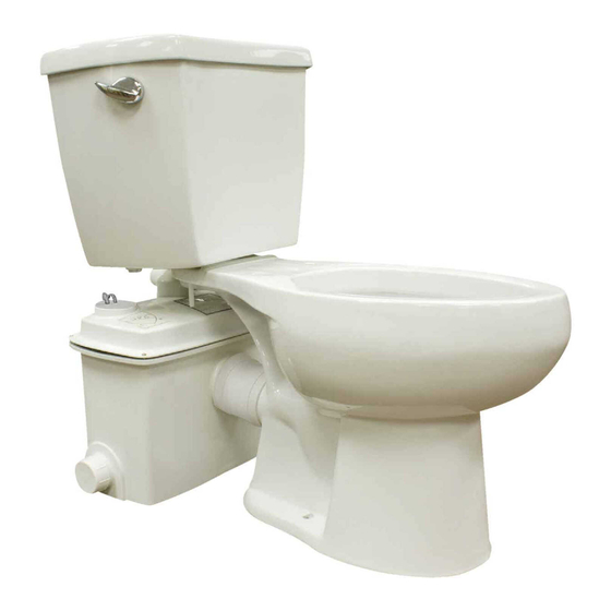
GENERAL PUMP USES The Powerflush Optima allows you to add a bathroom in a variety of places: Basements Workshops New Homes Garages Cabins Slab Construction Additions Commercial Buildings 1. The patented grinder/tank system is designed to move waste water and sewage up to existing sewer lines recommended for installations up to 20 ft. - Page 6 GENERAL PUMP USES This grinder/tank system can be used in the following installations: 3. Exposed Installation (grinder/tank unit is visible behind toilet). IL1730 4. Hidden Installation (grinder/tank unit is hidden behind wall). For installation behind a wall, extension kit Grinder/Tank Unit 023260 (sold separately) is required.
-
Page 7: Dimensions
DIMENSIONS All dimensions are in inches. 17-1/2 in. 14-3/8 in. Dim A. Dim A: 20 in. S1201 Round Bowl = 29 in. S1202 Elongated Bowl = 31.5 in. S1203 Elongated Bowl - 31.5 in. LOCATION SELECTION AND LEVELING OF TANK NOTE: If grinder/tank unit wlll be hidden behind a wall, Grinder/Tank be sure to allow access to the pump &... -
Page 8: Toilet Assembly
TOILET ASSEMBLY 1. Turn the toilet tank upside down and rest on protective padding. Install the tank to bowl gasket over the bottom Toilet Tank threads of the flush valve, making sure that the tank gasket covers the flush valve nut and the tapered side is Tank to Bowl toward the bowl. -
Page 9: Water Supply Hookup
TOILET ASSEMBLY Item Description Toilet tank cover Toilet tank Toilet tank to toilet bowl gasket bolts Rubber toilet tank to toilet bowl gasket Water supply connection Water supply line rubber seal Water supply line adapter Water supply line (not included) Plastic flat washer Plastic nut Bolt cover... - Page 10 WATER SUPPLY HOOKUP 3. Connect the water supply line to the ballcock shank Ballcock that extends below the toilet tank by tightening the plastic adapter with rubber washer over the end of the ballcock shank. CAUTION: Do not overtighten. Ballcock shank may Toilet Rubber Washer split and void the warranty.
-
Page 11: Exposed Grinder/Tank Installation
EXPOSED PUMP UNIT INSTALLATION 3. Lightly mark the locations of the grinder/tank unit, toilet Grinder Pump Unit Location and closet screw set locations on the floor. Closet Screw Set Locations 4. Lightly mark the wall with the height of the grinder/tank Toilet Tank Bottom and Sides unit and the bottom and sides of the toilet tank to prevent interference from pipe runs during pipe installation. -
Page 12: Hidden Grinder/Tank Installation
HIDDEN PUMP UNIT INSTALLATION NOTE: Installing the grinder/tank unit behind a wall will Toilet Tank Bottom and Sides require an extension kit (P/N 023260) sold separately. 1. Place the toilet assembly a minimum of 1/2" from the wall and mark the closet screw set locations on the floor. Grinder/ tank unit IL1743... -
Page 13: Piping
PIPING 1. Cut and dry-fit the pipe and fittings as required for 1 in. 1" diameter discharge pipe (may be reduced to 3/4" Discharge Grinder/tank unit diameter if codes permit). While dry-fitting the discharge Pipe and discharge fitting Fittings pipe, position and mark the location of the grinder/tank unit discharge fitting. - Page 14 PIPING 4. Temporarily set the toilet in place to check that there is no piping interference. Remove the toilet and set it aside. IL1748 5. Using a 2 step PVC gluing system, connect the Discharge discharge piping and grinder/tank unit discharge fitting. Pipe CAUTION: When applying glue to discharge fitting, Discharge...
-
Page 15: Toilet Installation
TOILET INSTALLATION 1. Pre-drill holes for closet screw sets at the points marked Grinder/tank unit location earlier and install screws in holes. Closet Screw Set Locations Toilet Location IL1751 2. Place the toilet assembly over the closet screw sets. Install the anchoring hardware and tighten in an alternating pattern. - Page 16 TOILET INSTALLATION 4. For hidden installation, (using optional extension kit 023260) install the rubber couplings to both the grinder/ tank unit and the toilet discharge and secure to extension pipe with worm clamps provided. Grinder/tank unit Sched 40 PVC Pipe Couplings Clamps IL1754...
- Page 17 TOILET INSTALLATION 7. Plug the pump’s power cord into the GFCI outlet. GFCI Outlet R E S E T Pump Plug TE S T IL1756 8. Flush the toilet and watch for proper operation. Listen for the pump to start. The pump unit requires proper venting in order for toilet to flush.
-
Page 18: Adding Other Fixtures
ADDING OTHER BATHROOM FIXTURES 1. PowerFlush Optima is designed to accept additional Sink bathroom fixtures utilizing the two side inlets. Grinder Pump Unit Side Inlets IL1759 2. Additional fixtures can be attached either to the 2 in. MPT (outside diameter) or the 1½ in. slip (inside diameter). -
Page 19: Typical Installation
TYPICAL INSTALLATION NOTE: All installations must comply with all applicable Electrical and 8 Ft. Ceiling Plumbing Codes, including, but not limited, to National Electrical Code; Local; Regional and/or State Plumbing Codes, etc. 7 Ft. Ceiling Sub Floor 3/4” Thick Minimum 2 x 8 Floor Joists 8”... -
Page 20: Troubleshooting
TROUBLESHOOTING Condition Possible Cause Remedy Pump will not start or run. Low voltage, blown fuse, Have a qualified electrician check fuse and open circuit. circuit. Impeller bound. Contact the Technical Service Department. Motor or wiring shorted. Debris on float switch. Remove debris Pump starts too soon. -
Page 21: Warranty
WARRANTY Manufacturer warrants, to the purchaser and Contact Manufacturer at, 95 North Oak Street, subsequent owner during the warranty period, Kendallville, IN 46755, Attention: Customer every new product to be free from defects in Service Department to obtain any needed repair material and workmanship under normal use and or replacement of part(s) or additional information service, when properly used and maintained,... -
Page 22: Replacement Parts
REPLACEMENT PARTS For replacement parts, call our customer service department at 1-800-742-5044, 7:30 a.m. - 5 p.m., EST, Monday - Friday. S1201 S1202 S1203 ITEM DESCRIPTION PART NO. PART NO. PowerFlush Optima Md S1201, S1202 Sewage 1202-1000 removal system w/o toilet PowerFlush Optima Md S1203 Sewage removal 1202-1001 system w/o toilet (Premium Cutter)
Need help?
Do you have a question about the PowerFlush Optima S1201 and is the answer not in the manual?
Questions and answers