Table of Contents
Advertisement
Quick Links
Advertisement
Table of Contents

Related Manuals for ADTRAN 1200051L1


Summary of Contents for ADTRAN 1200051L1
-
Page 1: User Manual
Dual Port ISDN Service Unit User Manual 1200051L1 1200051L2 1200051L5 1200051L6 61200051L1-1D June 1998 ISU 2x64 Part Numbers U-Interface Version, 110 VAC S/T-Interface Version, 110 VAC S/T-Interface International, 110 VAC S/T-Interface International, 230 VAC... - Page 2 Trademarks: Ascend is a registered trademark of Ascend Communications, Inc. ISU is a trademark of ADTRAN, Incorporated. Macintosh is a registered trademark of Apple Computer, Inc. Teleos is a registered trademark of Teleos Communications, Inc. Windows is a registered trademark of Microsoft corporation.
- Page 3 If experiencing difficulty with this equipment, please contact ADTRAN for repair and warranty information. The tele- phone company may require this equipment to be discon- nected from the network until the problem is corrected, or it is certain the equipment is not malfunctioning.
-
Page 4: Federal Communications Commission
FEDERAL COMMUNICATIONS COMMISSION RADIO FREQUENCY INTERFERENCE STATEMENT This equipment has been tested and found to comply with the limits for a Class A digital device, pursuant to Part 15 of the FCC rules. These limits are designed to provide reasonable protection against harmful interference when the equipment is operated in a commercial environment. - Page 5 CANADIAN EMISSIONS REQUIREMENTS This digital apparatus does not exceed the Class A limits for radio noise emissions from digital apparatus as set out in the interference-causing equipment standard entitled "Digital Appara- tus," ICES-003 of the Department of Communications. Cet appareil numerique respecte les limites de bruits radioelectriques applicables aux appareils numeriques de Class A prescrites dans la norme sur le materiel brouilleur: "Appareils Numer- iques,"...
- Page 6 CANADIAN EQUIPMENT LIMITATIONS Notice: The Canadian Industry and Science Canada label identifies certified equipment. This certification means that the equipment meets certain telecommunications network protective, operational, and safety requirements. The Department does not guarantee the equipment will operate to the user’s satisfaction. Before installing this equipment, ensure that it is permissible to be connected to the facilities of the local telecommunications company.
-
Page 7: Table Of Contents
Chapter 1. Understanding ISDN and the ISU 2x64 ... 1 ISDN Overview ... 1 The ADTRAN ISU 2x64... 1 ISU 2x64 Interoperability ... 4 ISU 2x64 Single Port Operation... 4 Recommended Operating Protocols... 6 Chapter 2. ISDN Service ... 9 ISDN Ordering Codes ... - Page 8 Table of Contents Software Version ... 26 Loopback Both DTEs ... 26 Test 2047 Both ... 26 Chapter 6. Configuration ...27 Dial Line Operation... 27 Setting the Switch Protocol ... 28 Setting the Call Type... 31 Speech ... 31 Audio ... 31 Data 56kbps...
- Page 9 DSR Options ... 52 Flow Control (asynchronous data format)... 52 Data Format (asynchronous)... 53 Transmit Clock (synchronous data format) ... 53 Autobaud ... 54 Setting Protocol Options ... 55 Clear Channel ... 56 BONDING mode 1 ... 56 TXINIT... 57 TXFA...
- Page 10 Table of Contents Chapter 9. Security and Remote Configuration ...73 Security ... 73 Set Password ... 74 Lock Keypad ... 74 Remote Config ... 74 Cfg. Rmt. Unit ... 75 Set Password ... 75 Lpbk remote 1B... 75 Lpbk remote 2B... 75 Chapter 10.
- Page 11 Figure 1-1: ISU 2x64 Rear Panel ... 2 Figure 1-2: ISU 2x64 Front Panel... 4 Figure 1-3: ISU 2x64 Interoperability ... 5 Figure 3-1: VT 100 Maintenance Help Screen ... 15 Figure 4-1: Current Status Menu... 18 Figure 4-2: VT 100 Status Screen ... 21 Figure 4-3: VT 100 Configuration Screen ...
- Page 12 List of Figures Figure 6-20: Transmit Clock Menu Tree... 54 Figure 6-21: Protocol Menu Tree ... 55 Figure 6-22: Protocol BONDING, Mode 1 Menu Tree ... 57 Figure 6-23: PPP Menu Tree... 61 Figure 7-1: VT 100 Dial Options Screen... 63 Figure 7-2: Dial Menu Tree ...
- Page 13 Table 1-A: DTE Indicators ... 3 Table 1-B: Recommended Operating Modes ... 7 Table 6-A: Rate Adaptation Protocols ... 60 Table 10-A: Troubleshooting Calls... 84 Table E-A: EIA-232 Interface ... 119 Table E-B: RS-530 Interface ... 120 Table E-C: V.35 Interface... 121 Table E-D: RS-366 Interface ...
- Page 14 List of Tables viii ISU 2x64 Dual Port ISDN Service Unit User Manual 61200051L1-1D...
-
Page 15: Chapter 1. Understanding Isdn And The Isu 2X64
THE ADTRAN ISU 2X64 ADTRAN’s ISU™ 2x64 is a stand-alone ISDN service unit that connects data terminal equipment to the ISDN network. The ISU 2x64 is a dual-port ISDN terminal adapter available with an op- tional integrated NT1. -
Page 16: Figure
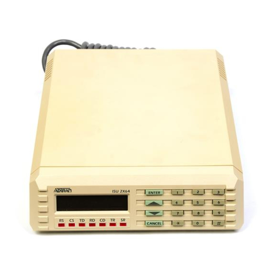
Chapter 1.Understanding ISDN and the ISU 2x64 The ISU 2x64 features two RS-530/EIA-232 DTE interfaces and two RS-366 dial interfaces (see Figure 1-1). An RS-530/EIA-232- to-V.35 adapter is available to support V.35 DTE interfaces. Syn- chronous data transfer rates from 2400 bps to 128 kbps and asyn- chronous rates from 1200 bps to 115.2 kbps are supported on a single DTE interface. -
Page 17: Table 1-A: Dte Indicators
The ISU 2x64 allows the user to migrate ISDN into existing net- work services and data communications equipment. The ISU 2x64 interoperates with ISU 128s, Switched 56 DSUs, various ISDN terminal adapters, and BONDING inverse multiplexers (for example ASCEND®, PROMPTUS, and Teleos®). For instance, in a video conferencing application, this compatibility allows the ISU 2x64 to interoperate with networks utilizing two Switched 56 DSUs. -
Page 18: Isu 2X64 Interoperability
ISU 2X64 SINGLE PORT OPERATION The ADTRAN ISU 2x64 is designed to operate over multipoint ISDN lines in North America that will require two Service Profile Identification (SPID) numbers from the telephone company when the ISDN lines are installed. - Page 19 Chapter 1. Understanding ISDN and the ISU 2x64 61200051L1-1D ISU 2x64 Dual Port ISDN Service Unit User Manual...
-
Page 20: Recommended Operating Protocols
Chapter 1.Understanding ISDN and the ISU 2x64 When the ISU 2x64 is used on an existing ISDN line that is not multipoint, with one SPID or no SPID numbers, additional con- siderations should be addressed. If DTE specific operation is desired, the ISDN line must be converted to multipoint operation (2 SPIDS). - Page 21 Sync/ Call Type Protocol Async DIAL-64K BONDING Sync 56000 Clear Chan Sync 48000 Sync 2400 V.110 Sync 2400 V.120 Sync 9600 Tlink Sync 2400 Sync 38400 PPP async-sync Async 1200 BONDING Async 2400 V.110 Async 1200 V.120 Async 1200 Tlink Async 1200 Async...
- Page 22 Chapter 1.Understanding ISDN and the ISU 2x64 All asynchronous rates support flow control. All dial-up modes support front panel, DTR, RS-366, AT command, and V.25 dialing methods. Rates marked with f require flow control. Given a choice between two protocols, pick the protocol closer to the top of the list.
-
Page 23: Chapter 2. Isdn Service
ISDN Basic Rate service for specific applications. ADTRAN and Bellcore have registered and tested eight generic IOCs. These IOCs are supported by all major local exchange car- riers as well as several independent carriers. After reviewing the following list, order ISDN lines from the local service provider. - Page 24 Chapter 2.ISDN Service application, then Capability R (previously Generic Data I ) may be more cost-effective. ADTRAN has registered the following ISDN ordering codes to support a variety of tariffs and applications: Capability S (previously Generic Data M) • 2B service •...
- Page 25 B1 (previously Generic Data B) • 1B service • Data only • One directory number Capability C (previously Generic Data C) • 1B service • Alternating voice and data • One directory number I2 (previously Generic Data I-1DN) • 2B service •...
- Page 26 Chapter 2.ISDN Service J2 (previously Generic Data J) • 2B service • 1B alternating voice/data, 1B data only • Two directory numbers M5 (previously Generic Data M-1DN) • 2B Service • 1B alternating voice/data, 1B data only • One directory number M5 is not available for services provided by Northern Telecom or AT&T switches.
-
Page 27: Chapter 3. Installation
LAD circuit. If using ISU 2x64, part number 1200051L1 or 1200051L3, connect the telephone company provided ISDN Basic Rate U-Interface to the RJ-45 connector marked ISDN IFC. An external NT1 is not needed in this configuration. -
Page 28: Dte Data Connection
Chapter 3.Installation If using ISU 2x64, part number 1200051L2, 1200051L4, 1200051L5, or 1200051L6, connect an ISDN Basic Rate S/T interface to the RJ- 45 connector marked ISDN IFC. The S/T interface can be pro- vided from an S/T line card of an ISDN switch or PBX, or from an NT1 network termination unit. -
Page 29: Maintenance Interface
Maintenance port using an EIA-232 cable. This interface can be used to set internal S-registers, dial ISDN connec- tions, and disconnect calls. This port also allows ADTRAN Tech- nical Support personnel to retrieve vital information from the unit if a problem is encountered during initial configuration of... -
Page 30: Dial Interface Connection
Chapter 3.Installation DIAL INTERFACE CONNECTION If out-of-band RS-366 dialing is required for applications such as videoconferencing or FAX machines, the dialing interfaces of the host DTE should be connected to the dial ports marked RS-366. Pin assignments for the RS-366 connector are listed in the appen- dix, Connector Pinouts. -
Page 31: Chapter 4 Operation
MENU NAVIGATION Moving through the various menu selections on the ISU 2x64 is a simple task. Four function keys on the left-hand side of the key- pad allow the user to enter, exit, and scroll through the various menu branches. The four function keys are defined below. To aid the reader, function keys are represented in bold, initial caps text. -
Page 32: Front Panel Dte Indicators
Chapter 4.Operation switch type, SPIDs, LDNs, or Leased/dial line. Also, items such as bit rate, protocol, and call type take effect only at the begin- ning of a new call. Front Panel DTE Indicators The front panel DTE indicators (see Figure 4-1) reflect the status of each DTE port on the ISU 2x64. -
Page 33: Vt 100 Menu Support
VT 100 Menu Support When connected to an asynchronous VT 100 terminal or VT 100 terminal emulator, use the built-in ISU 2x64 menu system for configuration of both DTE ports. The VT 100 screens can be acti- vated by typing AT!V while connected to either DTE port (in AT command mode), or by typing !V at the prompt while using the maintenance port. -
Page 34: Status Buffer
Chapter 4.Operation The menu tree allows for set up and operation of the ISU 2x64 from the front panel. The main branches of the menu tree follow: STATUS TEST CONFIG (ConÞguration) DIAL Status Buffer Selecting 1=STATUS from the top of the menu tree displays the contents of the status buffer. -
Page 35: Status Screen
Status Screen To determine the current status of the unit, press Ctrl+V to access the Status Screen (see Figure 4-2). The Status Screen displays unit information such as the loop status, software revision, the result of the initial self test, and the status buffer messages. (An expla- nation of status buffer messages can be found in Status Buffer Messages on page 99.) 61200051L1-1D... -
Page 36: Configuration Screen
Chapter 4.Operation Configuration Screen Once the unit is selected using the terminal interface, the display shows the Configuration Menu (see Figure 4-3). This screen shows the current configuration, line, and call status for the selected unit. See Configuration on page 27 for more information about configuring the ISU 2x64. -
Page 37: Chapter 5. Testing
TEST OPTIONS Selecting 2=TEST from the top of the menu tree (Figure 5-2) or Ctrl + T from any VT 100 screen displays available local testing options; this screen is shown in Figure 5-1. 61200051L1-1D ISU 2x64 Dual Port ISDN Service Unit User Manual Chapter 5 Testing Figure 5-1... -
Page 38: Loopback Dte
Chapter 5.Testing 1=STATUS 2=TEST 3=CONFIG 4=DIAL Loopback DTE This test causes the DTE port to loop back toward user equip- ment. This allows a bit error rate test (BERT) to be performed from the local end-user equipment to the ISU 2x64 to verify proper cable connection, etc. -
Page 39: Loopback Remote
Loopback Remote This test causes the ISU 2x64 to issue a V.54 inband loopback command to a far-end unit. External test equipment must be used to generate/check test patterns. To use this feature, both units must be configured for Clear Channel operation and the far- end unit must be able to respond to V.54 loopback commands. -
Page 40: Nebe/Febe
Chapter 5.Testing The ISU 2x64 must be optioned for Clear Channel operation for DDS and V.54 loopbacks to take effect. NEBE/FEBE This test reports the quality of the network connection between the T-1 and the switch by viewing the number of near-end block errors (NEBE) and far-end block errors (FEBE) occurring on the ISDN interface. -
Page 41: Chapter 6. Configuration
DIAL LINE OPERATION This section explains how to configure the ISU 2x64 when using ISDN Basic Rate switched service. Figure 6-3 illustrates the entire menu tree. The following are step-by-step procedures for configuring the unit for dial line operation, switch protocol, call type, terminal ID, dial options, auto answer, answer tone, connect timeout, call screening, and SBus termination. -
Page 42: Setting The Switch Protocol
Chapter 6. Configuration Setting the Switch Protocol Find out what kind of ISDN switch the local CO is using by asking the telephone administrator or telephone company representa- tive. Configure the ISU 2x64 for either Northern Telecom DMS- 100, AT&T 5ESS standard (usually an AT&T 5ESS, NT DMS-100 EWSD). -
Page 43: Lcd Configuration Menu Tree
STATUS ‘Buffer Display’ 1=Switch Protocl <Use Up and Down keys to Scroll> 2=Call type dte#1 TEST 1=Loopback DTE 2=Loopback Netw. dte#2 3=Terminal ID 3=Loopback Proto 4=Loopback Remot 5=Test Remote 6=Lpbk Disable 1=No Rem Lpbks 4=Busy Out 7=NEBE/FEBE 2=DDS Accepted 8=Software Ver 3=V54 Accepted 9=Lpbk Both DTE 4=DDS + V54 Accept... - Page 44 Chapter 6. Cofiguration ISU 2x64 Dual Port ISDN Service Unit User Manual...
-
Page 45: Setting The Call Type
Setting the Call Type Call type is configured for both DTE#1 and DTE#2. When using the front panel, select the appropriate DTE with either arrow key and press Enter. When using a VT 100 terminal, select the option number corresponding to the appropriate DTE and press Return. The Call type can be configured four different ways, depending on the type of service used: Speech , Audio, Data 56 kbps, or Data 64 kbps. -
Page 46: Smart Dial Strings
Chapter 6. Configuration Smart Dial Strings In some cases during a dial session it may be desired to change the call type temporarily. At the end of a dialed phone number, a #1,2,3, or 4 can be used to change the call type. A #1 changes it to speech, #2 to Audio, #3 to 56K, and #4 to 64K. -
Page 47: Setting The Ldn
Setting the LDN This option allows the entry of 0, 1, or 2 LDNs. The LDN is used when receiving BONDING calls or receiving separate calls for each DTE connection. The LDN is the seven-digit local phone number assigned to the line. When entering an LDN using the front panel, use the Up and Down arrow keys to select between LDN DTE#1 and LDN DTE#2. -
Page 48: Enabled
Chapter 6. Configuration Feature buttons are buttons that are normally available on ISDN telephone sets. The ISU 2x64 simulates pressing a feature button when the Busy Out Port option is changed. When the Busy Out Port option is changed, the ISU 2x64 sends a Feature Activation message to the switch using the feature button number stored in S-register 23. -
Page 49: Dial Options, Rs-366 Menu Tree
RS-366 parallel dialing port, configure the unit for RS-366 dialing. (See Figure 6-4.) This enables the RS-366 port on the rear of the unit. Whenever this dialing mode is enabled, data terminal ready (DTR) must be active before a call is placed. The call may be dis- connected by dropping DTR, or from the front panel by selecting the # (pound) key to go directly to the Dial menu and selecting 1=Hang up line, then Enter. -
Page 50: At Commands
Chapter 6. Configuration The ISU 2x64 assumes the dial string is fully entered if more than 20 sec or EON: 20 seconds elapse since the last digit was keyed, or the unit receives the EON command. The ISU 2x64 assumes the dial string is fully entered only if the Wait for EON: unit receives the EON command. - Page 51 be terminated at any time by transmitting the CTRL+X (ASCII 018) after the AT attention code. The ISU 2x64 ignores this com- mand line and issues an OK response. The command line may contain a single command or a series of commands after the AT attention code.
- Page 52 Chapter 6. Configuration Reading an S-register String Type ATSS followed by the number of the string S-register to be read followed by a question mark and press Enter. Example: To Change an S-register Type ATS followed by the number of the S-register to be changed, an equal sign, the numeric value to be assigned to the register, then press Enter.
-
Page 53: V.25
V.25 Configuring the ISU 2x64 for V.25 bis (see Figure 6-5) enables inband dialing over a DTE interface using asynchronous or syn- chronous V.25 bis commands. V.25 bis can be used to establish and end a call. Disconnecting calls can also be done from the front panel (as described previously), from a VT 100 terminal, or from the far-end unit. -
Page 54: Dial Line, Auto Answer Menu Tree
Chapter 6. Configuration The ISU supports the following V.25 bis commands to control automatic calling and answering: CRN ....Call Request (number in command) CRS . -
Page 55: Data Bits Menu Tree
1=Netw. options 1=Asynchronous 2=DTE options 3=CONFIG 2=Synchronous 3=Protocol 4=Quick setup 5=Security 6=Remote Config The setting in Figure 6-8 allows for V.25 bis messages in asyn- chronous (start/stop) data format. 1=Dial Line 1=Netw. options 2=Leased Line 3=CONFIG 2=DTE options 3=Protocol 4=Quick setup 5=Securtiy 6=Remote Config Although V.25 bis allows asynchronous data format, asynchro-... -
Page 56: Disabled
Chapter 6. Configuration The first byte of each packet contains all ones (A = FF HEX), and the second byte of each packet (the C byte) is either 13 HEX or 03 HEX if not the final packet. V.25 SYNC BISYNC Dialing To set the Dial Options for V.25 BISYNC, choose 3=V.25 BISYNC from the front panel or the VT 100 terminal (see Figure 6-8 for menu tree). -
Page 57: Enabled
Hang up line command or answered using the Answer Call command. (These commands are found under the Dial branch of the menu tree. See Front Panel Dialing Options on page 63.) Enabled When Enabled is selected, the incoming call is answered. If that call is a BONDING call and requires two B channels, the second call is answered. -
Page 58: No Answer Tone (Default)
Chapter 6. Configuration 1=Netw. options 3=CONFIG 2=DTE options 3=Protocol 4=Quick setup 5=Security 6=Remote Config No Answer tone (Default) This option disables the Answer tone on all calls. Incoming tone This option enables the Answer tone on incoming calls. Outgoing tone This option enables the Answer tone on outgoing calls. -
Page 59: Setting Connect Timout
Setting Connect Timout Connect Timout sets the length of time that the ISU 2x64 waits for a far-end unit to answer an outgoing call. These choices are illustrated in Figure 6-10. 1=Netw. options 2=DTE options 3=CONFIG 3=Protocol 4=Quick setup 5=Security 6=Remote Config Setting Call Screening Call Screening allows the ISU 2x64 to either answer all incoming calls... -
Page 60: Sbus Termination
Chapter 6. Configuration When Call Screening is set to Ansr if SN0. . .9, an incoming call is not answered if the Call ID received from the switch does not match a stored number. Depending on the switch type, the Call ID may be presented in either a seven- or ten-digit format. -
Page 61: Leased Line Service
The SBus Termination resistors are not present on ISU 2x64 units equipped with the integrated NT1 (part numbers 1200051L1 and 1200051L3). Setting the SBus Termination resistance to on or off on these units has no effect on their operation and can be ignored. -
Page 62: Channel Rate
Chapter 6. Configuration modem application, where two ISU 2x64 units are directly con- nected without the use of channel banks (see Figure 6-14). The far-end unit should be configured for Slave and derives its clock- ing from the ISU 2x64 configured as Master. ISU 128 ENTER R S C S... -
Page 63: Sbus Termination
The SBus Termination resistors are not present on ISU 2x64 units equipped with the integrated NT1 (part numbers 1200051L1 and 1200051L3). Setting the SBus Termination resistance on these units has no effect on their operation and can be ignored. -
Page 64: Dte Options For Asynchronous And Synchronous Operation
Chapter 6. Configuration DTE Options for Asynchronous and Synchronous Operation The DTE options are configured separately for both DTE#1 and DTE#2. When using the front panel, select the appropriate DTE with either arrow key and press Enter. (See Figure 6-16 and 6-17.) When using the VT 100 terminal select the option number corre- sponding to the appropriate DTE and press Return. -
Page 65: Bit Rate
Bit Rate The Bit Rate can be set asynchronously for 300, 1200, 2400, 4800, 9600, 19200, 38400, 57600, and 115200 bps. The Bit Rate can be set synchronously for 2400, 4800, 9600, 19200, 38400, 48000, 56000, 64000, 112000, and 128000 bps. Connector Type The ISU 2x64 can provide either an EIA-232, RS-530, or V.35 inter- face to a user DTE by selecting the desired connector type. -
Page 66: Dtr Options
Chapter 6. Configuration DTR Options Ignore DTR causes the ISU 2x64 to disregard the state of the data terminal ready (DTR) pin. Cmd when Off forces the unit into the AT command processor mode when DTR is not asserted. To return online, DTR must be asserted, followed by the AT0 com- mand. -
Page 67: Data Format (Asynchronous)
1=Netw. options 2=DTE options 3=CONFIG 3=Protocol 4=Quick setup 5=Security 6=Remote Config Data Format (asynchronous) A frame consists of a start bit, 7 or 8 Data bits, 0 or 1 Parity bit, and 1 to 2 Stop bits. The settings for Data Bits, Parity Bits, and Stop Bits are available as shown in Figure 6-19. -
Page 68: Autobaud
Microsoft Windows® 95 Plug-and-Play specifica- tions. The file MDMADTN.INF is required. To obtain this file, contact ADTRAN Technical Support as shown on the inside back cover of this manual. ISU 2x64 Dual Port ISDN Service Unit User Manual... -
Page 69: Setting Protocol Options
BONDING mode 1 (Bandwidth on Demand Interoperability Group) • CCITT V.120 • CCITT V.110 • DSU 57.6 ASYNC • T-LINK (Dial DDS DSU/CSU) • SAP (Simple ADTRAN Protocol) • FALLBACK • PPP async-sync 1=Netw. options 2=DTE options 3=CONFIG 3=Protocol 4=Quick setup 5=Security... -
Page 70: Clear Channel
Chapter 6. Configuration Clear Channel Clear channel provides the entire bearer channel to the DTE with- out regard to data format or protocol. This provides a rate adap- tation at or near the ISDN circuit rate. The primary usage for Clear Channel in dial line mode is 56 kbps and 64 kbps synchro- nous. -
Page 71: Txinit
1=Netw. options 2=DTE options 3=CONFIG 3=Protocol 4=Quick setup 5=Security 6=Remote Config The timers are defined as follows: TXINIT This option specifies the length of time the originating endpoint attempts to detect BONDING negotiation pattern from the answering endpoint before determining the BONDING call has failed. -
Page 72: Txdeq
Async. Rev. This option specifies the negotiation revision for asynchronous BONDING. Rev. 1 specifies multi-vendor compatible negotiation. Rev. 0 specifies ADTRAN proprietary negotiation. This option has no effect on synchronous negotiation. V.120 The V.120 protocol is a CCITT compliant rate adaptation method providing DTE service between the ISU 2x64 and other V.120... -
Page 73: V.110
T-Link protocol. Figure 6-21 illustrates the menu path for selecting T-Link. The Simple ADTRAN Protocol (SAP) is a rate adaptation method which provides DTE service between ISU 2x64 units at a channel rate lower than the 64 kbps ISDN bearer. Selecting this menu item causes the ISU 2x64 to use SAP protocol. -
Page 74: Fallback
Chapter 6. Configuration The primary usage for SAP is general purpose asynchronous rate adaptation in a dial-up or leased environment. SAP only oper- ates on a 64 kbps data link. Figure 6-21 illustrates the menu path for selecting SAP. FALLBACK The FALLBACK asynchronous rate adaptation protocol provides the capability to automatically establish calls with other ISDN terminal adapters and Switched 56 DSUs, as well as other ISUs... -
Page 75: Point-To-Point (Ppp) Async-To-Sync
ISU hangs up the call. Point-to-Point (PPP) Async-to-Sync PPP provides a standard method for transporting multi-protocol datagrams over point-to-point links. The ADTRAN PPP async- sync protocol allows the ISU 2X64 and a PC or Macintosh® run- ning PPP software, to communicate with a PPP-compatible bridge or router. -
Page 76: Point-To-Point Protocol (Ppp)
Chapter 6. Configuration Point-to-Point Protocol (PPP) The ISU 2x64 can be configured for PPP from the protocol options of the configuration menu by selecting 1=PPP or by setting S-reg- ister S27 to a value of 0. The menu path is shown in Figure 6-23. Multilink PPP The ISU 2x64 can be configured for multilink PPP from the proto- col options of the configuration menu by selecting 2= Multilink... -
Page 77: Chapter 7. Dial Options
FRONT PANEL DIALING OPTIONS Selecting 4=DIAL or pressing the # key from the front panel dis- plays the available dialing options (see Figure 7-2). Access the VT 100 Terminal Dial Options Screen (Figure 7-1) by pressing Ctrl+D from any screen. The dial options are only available when the ISU is configured for Dial Line operation (not Leased Line). -
Page 78: Hang Up Line
Chapter 7.Dial Options Hang up line Terminates current call. Dial number Enter and dial a number from the keypad. If an error is made, press the Down arrow to edit the number. After the number is entered, press Enter to dial the number and save as stored num- ber 9 for redialing purposes. -
Page 79: Chapter 8. Quick Setup
QUICK SETUP CONFIGURATION To configure the DTE Options quickly and easily, the Quick Set- up menu is available to automatically set up the nine most com- mon DTE configurations. (See Figure 8-1.) For fine-tuning a particular application and DTE settings, see DTE Options for Asyn- chronous and Synchronous Operation on page 50 for step-by-step procedures for detailed configuration of the DTE Options. -
Page 80: Quick Setup
Chapter 8. Quick Setup Quick Setup To aid in configuring the ISU 2x64, nine common configurations are preset for Quick Setup. These include: • Synchronous dial operation for 56, 64, 112, and 128 kbps • Asynchronous dial operation for 57.6 and 15.2 kbps •... -
Page 81: Dial 64K Sync
Dial 64K sync* When the ISU 2x64 is configured for Dial 64K sync service, the fol- lowing parameters are automatically preset: Service type ... ISDN dial line Automatic answering ...Enabled ISDN call type... 64 kbps data Data protocol... Clear Channel DTE mode... -
Page 82: Dial 128K Sync
Chapter 8. Quick Setup Dial 128K sync* When the ISU 2x64 is configured for Dial 128K sync service, the following parameters are automatically preset: Service type ...ISDN dial line Automatic answering...Enabled ISDN call type ...64 kbps data Data protocol... BONDING mode 1 DTE mode... -
Page 83: Dial 115.2 Asyn
Dial 115.2 asyn* When the ISU 2x64 is configured for Dial 115.2 asyn service, the following parameters are automatically preset: Service type ... ISDN dial line ISDN call type... 64 kbps data Protocol ... BONDING mode 1 DTE mode... Asynchronous Data Bits... -
Page 84: Leased 64K
Chapter 8. Quick Setup Leased 64K When the ISU 2x64 is configured for Leased 64K service, the fol- lowing parameters are automatically preset: Service type ...Leased Line Network clock source ...Slave Channel rate ... 64K Data Protocol...Clear Channel DDS loopbacks enabled...Yes DTE mode... -
Page 85: Factory Setup
Factory Setup To restore the ISU 2x64 to the factory default setup, power the unit off and perform the following steps: While pressing 0, power the unit on. Continue pressing 0 until the front panel displays the top of the menu tree. 1=STATUS will be blinking. Factory default erases all stored phone numbers, SPIDs, and LDNs, and sets parameters as follows: Service type ... - Page 86 Chapter 8. Quick Setup ISU 2x64 Dual Port ISDN Service Unit User Manual 61200051L1-1D...
-
Page 87: Chapter 9. Security And Remote Configuration
Security and Remote Configuration SECURITY The ISU 2x64 provides a front panel keypad locking feature to pre- vent tampering with configuration settings. The feature requires a password to access menus below the top Current-Status menu level. The menu options are shown in Figure 9-1. 1=Netw. -
Page 88: Set Password
Chapter 9. Security and Remote Configuration password does not match the stored password, the LCD displays a brief message indicating that the entered password was invalid and the top menu is displayed. Set Password Set Password prompts the user to enter a numeric code that will be required for access to configuration menus from the front pan- el. -
Page 89: Cfg. Rmt. Unit
Cfg. Rmt. Unit Cfg. Rmt. Unit causes the ISU 2x64 to place a call to a remote ISU for configuration. The user is prompted for the number to dial and the password for accessing the remote unit. After the call is placed, the local unit sends the entered password to the remote unit. - Page 90 Chapter 9. Security and Remote Configuration ISU 2x64 Dual Port ISDN Service Unit User Manual 61200051L1-1D...
-
Page 91: Chapter 10. Troubleshooting
Continue to press down 0 for 15 seconds. This resets all the internal settings to factory defaults. If the ISU 2x64 still does not pass self test, call ADTRAN Technical Support for assistance; see the back of this manual for phone numbers. - Page 92 Chapter 10. Troubleshooting If the Euro ISDN or VN4 switch type is selected, the unit will not enter the Ready state until a setup message is sent or received (part number 1200051L5 and 1200051L6). Cycle power on the ISU 2x64, leaving it off for a minimum of 2 seconds.
- Page 93 ISDN basic rate line has a physical layer 1 problem. Ask them to check the line. If using the ISU 2x64 1200051L1 or 1200051L3 with the U- interface, tell them that you have an NT1-like device at...
- Page 94 (TEI). Ask them to check the line translation and ensure that the line supports dynamic TEI allocation. If using the ISU 2x64 part number 1200051L1 or 1200051L3 with the U-interface, tell them that you have an NT1 and ter- minal adapter device connected to the line.
- Page 95 Ask them to check the line translation and ensure that the ISDN line supports dynamic TEI allocation. If using the ISU 2x64 part number 1200051L1 or 1200051L3 with the U- interface, tell them that you have an NT1 and terminal...
- Page 96 Ask them to check the line translation, ensure that the ISDN line supports dynamic TEI allocation, and verify the SPID(s). If using the ISU 2x64 part number 1200051L1 or 1200051L3 with the U-interface, tell them that you have an NT1 and terminal adapter device con- nected to the line.
-
Page 97: If The Wrong Dte Port Answers A Call
If the Wrong DTE Port Answers a Call A common mistake that can easily be made is entering the SPID/ LDN pair swapped between the two DTE ports. For example, your telephone company has given you two SPID/LDN numbers as follows: SPID1 - 201555701111 SPID2 - 201555702222 If you were to enter the pairs for DTE#1 as SPID1/LDN2 and... -
Page 98: If You Cannot Connect Calls
Chapter 10. Troubleshooting If you Cannot Connect Calls See Table 10-A for corrective actions if you cannot place calls. Condition The ISU 2x64 reads Ready but calls cannot be placed. Local voice calls can be transmit- ted, but data calls to the same exchange cannot. -
Page 99: Chapter 11. Specifications
Network Interface • RJ-45 for ISDN Basic Rate U-Interface, part numbers 1200051L1 and 1200051L3 • RJ-45 for ISDN Basic Rate S/T Interface, part numbers 1200051L2, 1200051L4, 1200051L5, and 1200051L6. DTE Interface • Two DB-25s, each RS-530/EIA-232 interfaces (V.35 interfaces available with RS-530-to-V.35 adapters, part number... -
Page 100: Data Rates (Dte)
Chapter 11. Specifications Data Rates (DTE) When using single DTE interface: • 300 bps to 115.2 kbps asynchronous • 2400 bps to 128 kbps synchronous When using dual DTE interfaces: • 300 bps to 57.6 kbps asynchronous on each interface •... -
Page 101: Display
2.25" high x 8.75" wide x 11.00" deep, 3 lbs Power • 115 VAC, 60 Hz, 8 W maximum dissipation (part numbers 1200051L1, 1200051L2, and 1200051L5 ) • 220 VAC, 50 Hz, 10 W maximum dissipation (part numbers 1200051L3 and 1200051L4) •... - Page 102 Chapter 11. Specifications ISU 2x64 Dual Port ISDN Service Unit User Manual 61200051L1-1D...
-
Page 103: Appendix A. At Commands
This Appendix lists the supported AT commands and descrip- tions of their functions. Bold text indicates default settings. Command Function Answer. Puts the ISU 2x64 in answer mode. Dial. Precedes the telephone access number [ATD5551212]. Hang up. Disconnects the current call. On line. - Page 104 Appendix A: AT Commands Command Function Carrier Detect (CD) Control Line Options &C0 CD forced On &C1 CD normal &C2 CD off with local disconnect (LOCD) &C3 CD off with Link Down Data Terminal Ready (DTR) Control Line Options &D0 Ignore DTR &D1 DTR Off forces command...
- Page 105 Command Function DTE Data Type Options &Q0 DTE is async &Q1 DTE is sync Clear-To-Send (CTS) Control Line Options &R0 Follows RTS &R1 Forced CTS Data Set Ready (DSR) Control Line Options &S0 DSR forced On &S1 DSR if call up &S2 DSR if link up DTE Connector Data Synchronous Data Clocking Options...
- Page 106 Appendix A: AT Commands Command Function AT Command Response Message Options Response messages on Response messages off AT Command Response Message Types Response messages codes Response messages words AT Command Connect Message Options Simple connect message X1-7 Connect messages with bit rate Ready-To-Send (RTS) Control Line Options 1 mS delay 18 mS delay...
- Page 107 Command Function ISDN Switch Type Options (continued) TDX10* TDX1B* KDD* NTT* *Only available on part numbers 1200051L5 and 1200051L6. ISDN U-Interface Operational Mode Options ISU timing slaves to network (NT mode) ISU is U-interface timing master (LT mode) Data Flow Control Options No flow control Software CTS only...
- Page 108 Appendix A: AT Commands ISU 2x64 Dual Port ISDN Service Unit User Manual 61200051L1-1D...
-
Page 109: Appendix B. Current Status Messages
Appendix B Current Status Messages This appendix lists the status line messages and their definitions. Messages shown entirely in capital letters are generated by the ISDN network. Messages with lower case letters are generated by the ISU 2x64. AT&T-5ESS Ready The ISU is connected to an AT&T-5ESS switch and is ready to place/receive calls. - Page 110 Appendix B: Current Status Messages DMS-100 Ready The ISU is connected to a DMS-100 switch and is ready to place/ receive calls. Euro ISDN Ready The ISU 2x64 is connected to a Euro ISDN switch and is ready to place/receive calls. Getting TEI #1 The ISU is receiving its first TEI from the network.
- Page 111 Appendix B: Current Status Messages NET EOC LOOPBACK The ISU 2x64 has been commanded to perform an ISDN loopback toward the network. NET REM LOOPBACK The ISU 2x64 is performing a V.54 or DDS latching loopback to- ward the network. Ready The unit is ready to make or accept a call.
- Page 112 Appendix B: Current Status Messages DSTOP DSU 57.6 Async rate adaptation protocol. DSU57.6 ADTRAN DSU asynchronous protocol. FALLBACK FALLBACK rate adaptation protocol. Simple Adtran Protocol. TLINK TLINK rate adaptation protocol. V120 V.120 rate adaptation protocol. V110 V.110 rate adaptation protocol.
-
Page 113: Appendix C. Status Buffer Messages
Appendix C Status Buffer Messages Messages shown entirely in capital letters are generated by the ISDN network. Messages with lower case letters are generated by the ISU 2x64. Answer 1/2 The ISU answered a call on either the first or second B channel. The calling phone number is displayed if available. - Page 114 Appendix C: Status Buffer Messages Bad DTE baud The DTE bit rate does not match a valid bit rate for the protocol se- lected. Bad DTE bps Bonding negotiation determined the chosen DTE bit rate is in- valid. BAD_INFO_ELEM Call control error. Bad phone number ISU 2x64 attempted to call an invalid phone number.
- Page 115 Appendix C: Status Buffer Messages BUSY The called number is busy. CallID 1 in use ISU 2x64 tried to place a call using SPID 1 when SPID 1 was al- ready in use. CallID 2 in use ISU 2x64 tried to place a call using SPID 2 when SPID 2 was al- ready in use.
- Page 116 Appendix C: Status Buffer Messages DEST_OUT_OF_ORDER The called number is out of order. Dial1/2 The ISU 2x64 placed a call on either the first or second channel. The number called is displayed following the message. Discon1/2 The call on either the first or second channel was disconnected from the network.
- Page 117 Appendix C: Status Buffer Messages FACILITY_REJECTED A facility requested cannot be provided by the network. FACILITY_NOT_SUBSCRIBED The channel type requested has not been subscribed. FALLBACK ERROR Attempt to fallback to normal mode failed. FBW disconnect BONDING negotiation has failed due to a disconnect on a B- Channel.
- Page 118 Appendix C: Status Buffer Messages INVALID_ELEM_CONTENTS Call control error. INVALID_MSG_UNSPEC Invalid message, protocol error. INVALID_NUMBER_FORMAT The dialed number has an invalid format. L1 not up Call has been attempted while the network interface is not active. L2 not up Call has been attempted while the data link layer interface is not active.
- Page 119 Appendix C: Status Buffer Messages Need 64K call The BONDING protocol requires the ISU 2x64 to be configured for a 64kbps data call type. Negotiation fail The BONDING negotiation has failed. NETWORK BUSY The ISDN switch is busy and unable to process a call. NETWORK_CONGESTION The phone network is currently congested.
- Page 120 Bonding negotiation determined the far-end unit is not another ISU. (Asynchronous rates can only be supported between two ADTRAN ISUs when Rev. 0 Bonding Mode 1 is selected. Rev. 1 Bonding Mode 1 will interoperate with other vendor terminal adapters in asynchronous DTE operation.) RESP_TO_STAT_ENQ Response to status inquiry.
- Page 121 Appendix C: Status Buffer Messages SReg Set Error Local DTE invalid S-register setting. Sync BPS < 56K The synchronous bit rate selected is too slow for the BONDING protocol. Synch Mismatch Both ends bad synchronization. TAINIT expired Bonding timer TAINIT expired. TANULL expired Bonding timer TANULL expired, non BONDING equipment at- tempted to call into the ISU 2x64 while optioned for BONDING.
- Page 122 Appendix C: Status Buffer Messages TXINIT expired Bonding timer TXINIT expired, called non-BONDING equipment or B channel not error free. UNASSIGNED_NUMBER The phone number dialed does not exist. Unknown AT & cmd User issued an unknown AT command. UNSPECIFIED_CAUSE Received a cause message from the network that is not under- stood.
-
Page 123: Appendix D. S-Register List
S0...AUTO ANSWER S2...BREAK IN CHARACTER S3...END OF LINE CHARACTER S4...LINE FEED CHARACTER S5...BACK SPACE CHARACTER 61200051L1-1D ISU 2x64 Dual Port ISDN Service Unit User Manual Appendix D S-Register List Determines how the ISU 2x64 answers an incoming call. 0 = Disable (ISU 2x64 does not answer call) 1 = Enable (ISU 2x64 answers all calls) (default) 2 = Dump all calls Determines which key or character (in ASCII code) - Page 124 Bit 4 = 1: enables AT responses to be displayed in text form. Bit 4 = 0: enables AT responses to be displayed in nu- meric form. for asynchronous connections. 0 = ADTRAN orginal Async. Bonding 1 = Multivendor Async. Bonding (default) 61200051L1-1D...
- Page 125 S22...MSG BITS S23...MAKE BUSY FEATURE BUTTON NUMBER S24...V.120 Value determines whether or not the V.120 bit is set LOW LAYER COMP. in setup messages for CCITT V.120 calls. Some terminal S25...DTR DELAY S26...DTE RATE ADJUST S27...PPP MODE 61200051L1-1D ISU 2x64 Dual Port ISDN Service Unit User Manual Appendix D: S-Register List Miscellaneous message bits (bit 8 is most significant bit).
- Page 126 Appendix D: S-Register List S30 ...DTE CTS S31 ...DTE RTS S32 ...DTE DSR S33 ...DTE CD S34...DTE DTR S35...DTE CONN S40 ...BOND TXINIT ISU 2x64 Dual Port ISDN Service Unit User Manual Controls the operation of the DTE connector CTS line. 0 = Follows RTS 1 = Forced CTS (default) Controls operation of the RTS line.
- Page 127 S41...BOND TXFA S42...BOND TXADD01 S43...BOND TXDEQ S44 ...BOND TANULL S45...BOND TCID S46...V25 MODE 61200051L1-1D ISU 2x64 Dual Port ISDN Service Unit User Manual Appendix D: S-Register List Specifies the number of seconds both endpoints at- tempt to detect the BONDING frame pattern when a call is connected before deciding the BONDING call has failed.
- Page 128 Appendix D: S-Register List S47 ...RS 366 TIME S50 ...LINE MODE S51 ...LINE CLOCK S52 ...SWITCH TYPE *Only available on part numbers 1200051L5 and 1200051L6. S53 ...CALL TYPE ISU 2x64 Dual Port ISDN Service Unit User Manual Determines the amount of time the RS-366 port waits for either EON or inactivity to terminate a dial string before dialing a number.
- Page 129 S54...PROTOCOL TYPE S55...DIAL MODE S56...ECHO TONE S57...DDS TEST S58...CALL SCREENING 61200051L1-1D ISU 2x64 Dual Port ISDN Service Unit User Manual Appendix D: S-Register List Rate adaptation protocol type. 1 = Clear Channel (no rate adaptation) (default) 2 = BONDING mode 1 3 = SAP (Simple Asynchronous Protocol) 4 = T-link 5 = V.110...
- Page 130 Appendix D: S-Register List S59 ...CHANNEL RATE SS60...SPID1 LOC SS61...SPID2 LOC SS62...LDN1 LOC SS63...LDN2 LOC S70 ...DTE MODE S71 ...DTE RATE S72 ...DATA BITS S73 ...DTE PARITY ISU 2x64 Dual Port ISDN Service Unit User Manual Sets the available network bandwidth when the ISU 2x64 is in leased mode.
- Page 131 S74...DTE STOP S75...DTE FLOW S76...DTE CLOCK S135... The following are the string locations for stored numbers 0 - 9: SS80...SN0 LOC SS81...SN1 LOC SS82...SN2 LOC SS83...SN3 LOC SS84...SN4 LOC SS85...SN5 LOC SS86...SN6 LOC SS87...SN7 LOC SS88...SN8 LOC SS89...SN9 LOC S118 = 0 S118 =32 61200051L1-1D ISU 2x64 Dual Port ISDN Service Unit User Manual...
- Page 132 Appendix D: S-Register List ISU 2x64 Dual Port ISDN Service Unit User Manual 61200051L1-1D...
-
Page 133: Appendix E. Connector Pinouts
1 ...Shield ...I/O... Shield for cable 2 ...TD...I... Transmitted Data 3 ...RD...O... Received Data 4 ...RTS...I... Request to Send 5 ...CTS...O... Clear To Send 6 ...DSR ...O... Data Set Ready 7 ...SG ...I/O... Signal Ground 8 ...CD ...O... Carrier Detect 9 ...NC ...N/A ... -
Page 134: Figure E
Appendix E: Connector Pinouts 1 ... Shield ... I/O ... Shield for cable 2 ... TD-A ... I ... Transmitted Data 3 ... RD-A ... O... Received Data 4 ... RTS-A ... I ... Request To Send 5 ... CTS-A ... O... Clear To Send 6 ... -
Page 135: Rs-366 Interface
(Provided by RS-530/232-to-V.35 Adapter, part number 1200072L1) A ...Shield ...I/O... Shield for cable B ...SG ...I/O... Signal Ground C...RTS...I... Request To Send D ...CTS...O... Clear To Send E...DSR ...O... Data Set Ready F...CD ...O... Carrier Detect H ...DTR ...I... Data Terminal Ready J ...RI ...O... -
Page 136: Rj-45 Dial Line Connector U Interface
Appendix E: Connector Pinouts 1 ... Shield ... I/O ... Shield for cable 2 ... DPR ... I ... Digit Present 3 ... ACR... O... Abandon Call and Retry 4 ... CRQ ... I ... Call Request 5 ... PND ... O... Present Next Digit 6 ... - Page 137 61200051L1-1D ISU 2x64 Dual Port ISDN Service Unit User Manual Appendix E: Connector Pinouts Table E-F RJ-45 Dial Line Connector S/T Interface Description Table E-G Maintenance Connector Description RING...
- Page 138 Appendix E: Connector Pinouts ISU 2x64 Dual Port ISDN Service Unit User Manual 61200051L1-1D...
-
Page 139: Appendix F. Ordering Isdn Without Iocs
The following form has been designed to assist you. Complete and FAX this form to your telephone company to request the proper type of ISDN telephone line for use with the ADTRAN ISU 2x64. 61200051L1-1D... - Page 140 Appendix F: Ordering ISDN Without IOCs ISDN Service Ordering Information for the ADTRAN ISU 2x64 For ADTRAN ISU 2x64 applications, the following guide can be used as an aid in ordering basic ISDN service from your local telephone company. The ADTRAN ISU 2x64 ISDN Service Unit (part numbers 1200051L1 and 1200051L3) includes NT1 and Terminal Adapter functionality and supports data at rates up to 128 kbps.
- Page 141 For service offered from an AT&T 5ESS, request a multipoint line, with the following features: Feature B1 Service B2 Service Data Line Class Maximum B Channels Circuit Switched Voice Bearer (CSV) Channels Number of CSV calls Circuit Switched Data (CSD) Bearer Channels Number of CSD calls Terminal Type Turn the following features off:...
- Page 142 Appendix F: Ordering ISDN Without IOCs For service offered from a Northern Telecom DMS-100, request a multipoint line, with the following features. Line Type Electronic Key Telephone Sets (EKTS) Call Appearance Handling (CACH) Non-Initializing Terminal Circuit Switched Service Packet Switched Service Bearer Service Identify your long distance carrier of choice and request circuit-switched 64 kbps Clear Channel access if possible.
-
Page 143: Physical Interface
LOCAL INTERFACE REQUIREMENTS Physical Interface • ISDN Basic Rate Interface (BRI) line • U-interface reference point • 2B1Q line coding ISDN service must be provided from one of the following CO switches and protocols: Switch AT&T 5ESS Northern Telecom DMS-100 Siemens EWSD The interface provides the ability to allocate one dynamic (TEI) per phone number. - Page 144 Appendix F: Ordering ISDN Without IOCs Long Distance Service If facilities are available, subscribe to long distance service sup- porting the bearer capabilities previously listed. Request service supporting circuit-switched 64 kbps or 56 kbps access. It is rec- ommended that the same long distance carrier end-to-end throughout the network to be used.
-
Page 145: Table F-A: 5Ess Features
B1 service B2 service Data line class Maximum B channels Number of circuit switched voice (CSV) calls Circuit switched voice bearer channels Number of circuit switched data (CSD) calls Circuit switched data bearer channels Terminal type data bearer channels Multipoint lines require the phone company to create a SPID for each phone number on the line. -
Page 146: Table F-B: Dms Features
Appendix F: Ordering ISDN Without IOCs DMS-100 Protocol Version 1 Line Additional Parameters The Northern Telecom DMS-100 telephone switch supports a proprietary ISDN D-channel call control protocol called Pvc1 which is based on CCITT recommendations. The ISU 2x64 con- figured for switch-type DMS-100 is functional on lines providing this protocol on DMS-100 switches with software version BCS-32 or later. - Page 147 After Service Is Installed When the line is installed, the following information will be pro- vided by the local phone service provider: • A seven-digit LDN for the line. If the line is multipoint with two phone numbers, two LDNs are provided. •...
- Page 148 Appendix F: Ordering ISDN Without IOCs ISU 2x64 Dual Port ISDN Service Unit User Manual 61200051L1-1D...
-
Page 149: Acronyms
2B1Q 2 Binary, 1 Quarternary Alternate Mark Inversion B (Channel) A 64 kbps digital information channel BONDING Bandwidth On Demand Interoperability Group Bits per second Basic Rate Interface CCITT Consultative Committee for International Telegraphy and Te- lephony Carrier Detect Connect Incoming Call Clear to Send Data Communications Equipment Digital Multiplex Switching... - Page 150 Acronyms Primary Rate Interface SPCS Stored Program Controlled Switching System SPID Service Profile Identifier Terminal Adapter Terminal Equipment Terminal Endpoint Identifier Wide Area Network ISU 2x64 Dual Port ISDN Service Unit User Manual 61200051L1-1D...
-
Page 151: Glossary
asynchronous transmission Not Synchronous. A method of data transmission which allows characters to be sent at irregular intervals by preceding each character with a start bit and following it with a stop bit. The timing of the transmission is not determined by the timing of a previous character. - Page 152 Glossary CCITT Consultative Committee on International Telephony and Telegraphy. A body of the International Telegraph Union (ITU) which prepares recommendations, com- monly referred to as international standards, to resolve technical telegraph and telephone problems. central office (CO) In telephony, the facility housing the switching system and related equipment that provides telephone service for customers in the immediate geographical area.
- Page 153 dataphone digital service. AT&T private line service for transmitting data over a digital system. The digital transmission system transmits electrical signals direct- ly, instead of translating the signals into tone of varied frequencies as with tradi- tional analog transmission systems. Digital techniques provide more efficient use of transmission facilities, resulting in lower error rates and costs than analog sys- tems.
- Page 154 Glossary ISDN Integrated service digital network. A network architecture that enables end-to- end digital connections. The network supports diverse services through integrat- ed access arrangements and defines a limited set of standard, multipurpose inter- faces for equipment vendors, network providers, and customers. Interworking with a public switched telephone network is retained.
- Page 155 NEXT (near-end crosstalk) Unwanted energy transferred from one circuit to an adjoining circuit. Occurs at the end of the transmission link where the signal source is located. The absorbed energy is usually propagated in the direction opposite to the absorbing channel’s normal current flow.
- Page 156 Glossary synchronous 1. The condition occurring when two events happen in a specific time relationship with each other, both under control of a master clock. 2. A method of data trans- mission requiring the transmission of timing pulses to keep the sender and receiv- er synchronized in their communication used to send blocks of information.
- Page 157 2B+D The basic rate interface (BRI) in ISDN. A single ISDN circuit divided into two 64 kbps digital channels for voice or data and one 16 kbps channel for low speed data (up to 9,600 baud) and signalling. 2B+D is carried on one or two pairs of wires de- pending on the interface, the same wire pairs that today bring a single voice circuit into your home or office.
- Page 158 Glossary ISU 2x64 Dual Port ISDN Service Unit User Manual 61200051L1-1D...
-
Page 159: Index
Numerics 2B1Q leased digital service 5ESS custom line additional parameters 5ESS features adapters RS-530-to-V.35 always tone answer call answer tone setting async. rev. AT command processor 36, 37, 89 AT commands 85, 89 AT commands, AT&T 5ESS, audio auto answer setting autobaud B channel aggregation... - Page 160 Index current status menu current status messages data 56kbps data 64kbps data format (async) data rates (DTE) (network) dial 112K sync dial 115.2 asyn dial 128K sync dial 56K sync dial 57.6 asyn dial 64K sync dial interface connection dial line menu tree dial line operation dial line, dial menu tree...
- Page 161 installation ISU 2x64 installation interface maintenance interfaces 4, 86 interoperability ISDN ordering codes overview service ISU 2x64 dialing from 3, 4 front panel interfaces interoperability operation overview rear panel single port operation LCD configuration menu tree ldm 64K master LDNs setting leased 64K leased application with channel banks...
- Page 162 Index maintenance connector, RJ-45 dial line connector S/T inter- face, RJ-45 dial line connector U interface, RS-366, RS-530, V.35, point-to-point async-to-sync point-to-point protocol power PPP async-to-sync PPP protocol PPP with compression protocol options setting quick setup configuration quick setup menu tree 65, 66 quick setup, rate adaptation protocols...
- Page 163 TANULL TCID terminal ID setting test 2047 both test menu screen test menu tree test options test remote testing T-link transmit clock (async) troubleshooting troubleshooting calls TXADD01 TXDEQ TXFA TXINIT V.110 V.120 V.25 V.25 async dialing V.25 bis, V.25 HDLC flag V.25 sync bisync dialing V.25 sync HDLC Dialing 120, 121...
- Page 164 Index ISU 2x64 Dual Port ISDN Service Unit User Manual 61200051L1-1D...
-
Page 165: Product Support Information
Technical Support (888)4ADTRAN Repair and Return If ADTRAN Technical Support determines that a repair is needed, Technical Support will coordinate with the Customer and Product Service (CAPS) department to issue an RMA number. For infor-...