
Related Manuals for Abit SG-80


Summary of Contents for Abit SG-80
- Page 1 SG-80 Series (SG-80, SG-81) Intel Pentium 4 System Board Socket 775 User’s Manual Rev. 1.00...
- Page 2 Copyright and Warranty Notice The information in this document is subject to change without notice and does not represent a commitment on part of the vendor, who assumes no liability or responsibility for any errors that may appear in this manual. No warranty or representation, either expressed or implied, is made with respect to the quality, accuracy or fitness for any particular part of this document.
-
Page 3: Table Of Contents
Table of Contents Chapter 1. Introduction ... 1-1 1.1. Features & Specifications... 1-1 1.2. Layout Diagram (SG-80)... 1-3 1.3. Layout Diagram (SG-81)... 1-4 1.4. Jumpers & Connectors Description... 1-5 Chapter 2. Hardware Setup... 2-1 2.1. CPU Socket ... 2-1 2.2. System Memory ... - Page 4 3.2. Using BIOS ... 3-4 3.2.1. Standard CMOS Features ... 3-4 3.2.2. Advanced BIOS Features ... 3-7 3.2.3. Advanced Chipset Features ... 3-10 3.2.4. Integrated Peripherals ... 3-14 3.2.5. Power Management Setup ... 3-18 3.2.6. PnP/PCI Configurations... 3-20 3.2.7. PC Health Status ... 3-22 3.2.8.
-
Page 5: Chapter 1. Introduction
Introduction Chapter 1. Introduction 1.1. Features & Specifications • Designed for Intel with 800/533 MHz FSB • Supports Intel Hyper-Threading Technology Chipset • SIS 661FX/ 964 (L) Memory • Two 184-pin DIMM sockets • Supports DDR400 non-ECC un-buffered memory • Supports maximum memory capacity up to 2GB Graphic •... - Page 6 This motherboard is customized for certain system configurations; and may not fit system integration in all DIY ways. Before integrating this product, please check ABIT web site for recommended device listings, or contact sales/tech. support people. Specifications and information contained herein are subject to change without notice.
-
Page 7: Layout Diagram (Sg-80)
Introduction 1.2. Layout Diagram (SG-80) User’s Manual... -
Page 8: Layout Diagram (Sg-81)
Chapter 1 1.3. Layout Diagram (SG-81) SG-80 Series... -
Page 9: Jumpers & Connectors Description
Introduction 1.4. Jumpers & Connectors Description Jumpers Description CCMOS CMOS Memory Clearing Header Connectors AGP1 ATX_POWER ATX12V CD1/AUX1 CPUFAN SYSFAN/PWRFAN DIMM1/DIMM2 FDC1 FPIO_AUDIO1 IDE1/IDE2 PANEL1 PCI1/PCI2/PCI3 SATA1/SATA2 USB3/USB4 Description Accelerated Graphics Port Slot ATX Power Connectors Internal Audio Connectors CPU Fan Power Connector System/Power Fan Power Connectors DDR DIMM Slots Floppy Disk Drive Connector... - Page 10 Chapter 1 SG-80 Series...
-
Page 11: Chapter 2. Hardware Setup
Hardware Setup Chapter 2. Hardware Setup 2.1. CPU Socket This server board provides one 775-pin Zero Insertion Force (ZIF) socket to install the Intel Pentium 4 CPU. User’s Manual... -
Page 12: System Memory
2.2. System Memory This system board provides two 184-pin DDR DIMM slots for un-buffered and non-ECC modules with memory size expansible up to 2GB (DDR400). DIMM Total System Memory SG-80 Series DIMM Module 256MB, 512MB, 1GB 256MB, 512MB, 1GB Chapter 2 Total Memory 256MB ~ 1GB 256MB ~ 1GB... -
Page 13: Connectors, Headers, And Switches
Hardware Setup 2.3. Connectors, Headers, and Switches All the connectors, headers and switches mentioned here are depending on your system configuration. Some features you may (or may not) have to connect or to configure depending on the peripherals you have connected. WARNING: Always power off the computer and unplug the AC power cord before adding or removing any peripheral or component. -
Page 14: Fan Connectors (Cpufan, Sysfan, Pwrfan)
2.3.2. FAN Connectors (CPUFAN, SYSFAN, PWRFAN) These connectors each provide power to the cooling fans installed in your system. • CPUFAN: Power connector for CPU cooling fan • SYSFAN, PWRFAN: Power connector for System and Power Fan WARNING: These fan connectors are not jumpers. DO NOT place jumper caps on these connectors. -
Page 15: Cmos Memory Clearing Header (Ccmos)
Hardware Setup 2.3.3. CMOS Memory Clearing Header (CCMOS) This header uses a jumper cap to clear the CMOS memory. • Pin 2-3 shorted (default): Normal operation. • Pin 1-2 shorted: Clear CMOS memory. ATTENTION: Turn the system power off first (including the +5V standby power) before clearing the CMOS memory. -
Page 16: Front Panel Switches & Indicators Connection Headers (Panel1)
2.3.4. Front Panel Switches & Indicators Connection Headers (PANEL1) These headers are used for connecting switches and LED indicators on the chassis front panel. The mark “+” align to the pin in the figure below stands for positive polarity for the LED connection. SG-80 Series Definition HD LED +... -
Page 17: Additional Usb Port Connection Header (Usb3, Usb4)
Hardware Setup 2.3.5. Additional USB Port Connection Header (USB3, USB4) These headers each provide 2 additional USB 2.0 ports connection through an USB cable designed for USB 2.0 specifications. Pin Signal Name USBPWR USBPWR USB_FP_P0- USB_FP_P1- USB_FP_P0+ USB_FP_P1+ 10 NC Function Front Panel USB Power Front Panel USB Power... -
Page 18: Front Panel Audio Connection Header (Fpio-Audio1)
2.3.6. Front Panel Audio Connection Header (FPIO-AUDIO1) This header provides the connection to audio connector at front panel. • To use the audio connector at front panel, remove all the jumpers on this header, and then connect to front panel by the extension cable provided with the chassis. -
Page 19: Accelerated Graphics Port Slot (Agp1)
Hardware Setup 2.3.7. Accelerated Graphics Port Slot (AGP1) This slot supports an optional AGP graphics card up to AGP 8X/4X mode. ATTENTION: This motherboard does not support 3.3V AGP cards. Use only 1.5V or 0.8V AGP cards. User’s Manual... -
Page 20: Internal Audio Source Connectors (Cd1, Aux1)
2-10 Chapter 2 2.3.8. Internal Audio Source Connectors (CD1, AUX1) These connectors connect to the audio output of internal CD-ROM drive or add-on card. SG-80 Series... -
Page 21: Floppy Disk Drive Connector (Fdc)
Hardware Setup 2.3.9. Floppy Disk Drive Connector (FDC) This connector supports two standard floppy disk drives via a 34-pin 34-conductor ribbon cable. Connecting the Floppy Disk Drive Cable: 1. Install one end of the ribbon cable into the FDC connector. The colored edge of the ribbon cable should be aligned with pin-1 of FDC connector. -
Page 22: Ide Disk Drive Connectors (Ide1, Ide2)
2-12 Chapter 2 2.3.10. IDE Disk Drive Connectors (IDE1, IDE2) These IDE ports each connects up to two IDE drives at Ultra ATA/100 mode by one 40-pin, 80-conductor, and 3-connector Ultra ATA/66 ribbon cables. Connect the single end (blue connector) at the longer length of ribbon cable to the IDE port on system board, and the other two ends (gray and black connector) at the shorter length of the... -
Page 23: Serial Ata Connectors (Sata1, Sata2)
Hardware Setup 2-13 2.3.11. Serial ATA connectors (SATA1, SATA2) These connectors are provided to attach one Serial ATA device at each channel via Serial ATA cable. User’s Manual... -
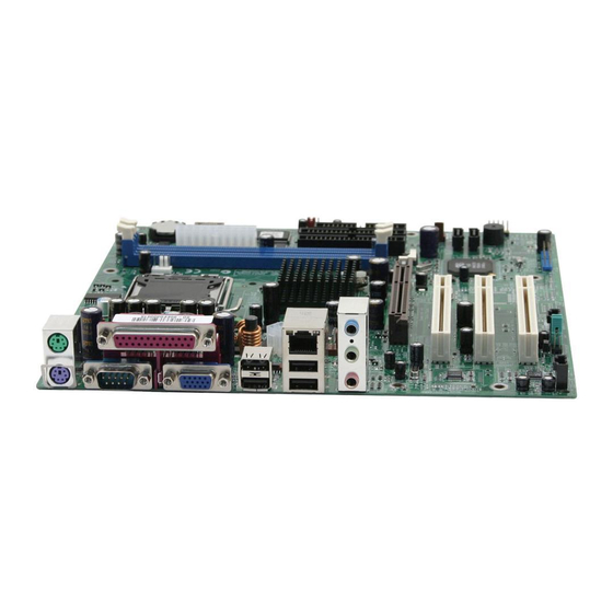
Page 24: External I/O Panel
2-14 2.3.12. External I/O Panel • Mouse: PS/2 mouse connector. • Keyboard: PS/2 keyboard connector. • LPT1: Parallel port connector. • COM1: Serial port connector. • VGA1: Monitor signal connector. • USB1/USB2: USB 2.0 connectors. • LAN1:10/100Mbps LAN connectors. • AUDIO: Mic In: Connects to the plug from external microphone. -
Page 25: Chapter 3. Bios Setup
3.1. About the Setup Utility The computer uses the latest Award BIOS with support for Windows Plug and Play. The CMOS chip on the motherboard contains the ROM setup instructions for configuring the motherboard BIOS. The BIOS (Basic Input and Output System) Setup Utility displays the system’s configuration status and provides you with options to set system parameters. -
Page 26: Entering The Setup Utility
3.1.2. Entering the Setup Utility When you power on the system, BIOS enters the Power-On Self Test (POST) routines. POST is a series of built-in diagnostics performed by the BIOS. After the POST routines are completed, the following message appears: Press <DEL>... -
Page 27: Updating The Bios
Install new BIOS as follows: 1. If your motherboard has a BIOS protection jumper, change the setting to allow BIOS flashing. 2. If your motherboard has an item called Firmware Write Protect in Advanced BIOS features, disable it. -
Page 28: Using Bios
Chapter 3 3.2. Using BIOS When you start the Setup Utility, the main menu appears. The main menu of the Setup Utility displays a list of the options that are available. A highlight indicates which option is currently selected. Use the cursor arrow keys to move the highlight to other options. - Page 29 (Master and Slave). Use these items to configure each device on the IDE channel. This motherboard features two SATA connectors supporting two SATA drives. SATA refers to Serial ATA (Advanced Technology Attachment), the standard interface for the IDE hard drives which are currently used in most PCs.
- Page 30 Floppy 3 Mode refers to a 3.5-inch diskette with a capacity of 1.2 MB. Floppy 3 Mode is sometimes used in Japan. Video (EGA/VGA) This item defines the video mode of the system. This motherboard has a built-in VGA graphics system; you must leave this item at the default value. Halt On (All, But Keyboard) This item defines the operation of the system POST (Power On Self Test) routine.
-
Page 31: Advanced Bios Features
BIOS Setup 3.2.2. Advanced BIOS Features This option defines advanced information about your system. CPU Feature Scroll to this item and press <Enter> to view the following screen: Users please note that this function is only available for Prescott CPUs. User’s Manual... - Page 32 Chapter 3 Thermal Management This item displays CPU’s temperature and enables you to set a safe temperature to Prescott CPU. TM2 Bus Ratio This item represents the frequency (bus ratio) of the throttled performance state that will be initiated when the on-die sensor goes from not hot to hot). TM2 Bus VID This item represents the voltage of the throttled performance state that will be initiated when the on-die sensor goes from not hot to hot.
- Page 33 BIOS Setup CPU L3 Cache (Enabled) This item is only available when processors support L3. Some high-end processors support L3. If the CPU do support L3, you may set this item to enable or disable. Leave this item at the default value for better performance. Hyper-Threading Technology (Enabled) This item is only available when the chipset supports Hyper-Threading and you are using a Hyper-Threading CPU.
-
Page 34: Advanced Chipset Features
3.2.3. Advanced Chipset Features These items define critical timing parameters of the motherboard. You should leave the items on this page at their default values unless you are very familiar with the technical specifications of your system hardware. If you change the values incorrectly, you may introduce fatal errors or recurring instability into your system. - Page 35 BIOS Setup DRAM Clock/Timing Control: Scroll to this item and press <Enter> to view the following screen: DRAM Timing Control Enables you to select the CAS latency time in HCLKs of 2, 2.5, or 3. The value is set at the factory depending on the DRAM installed. Do not change the values in this field unless you change specifications of the installed DRAM or the installed CPU.
- Page 36 3-12 RAS to CAS Delay (tRCD): This is the amount of time a CAS is performed after a RAS. The lower the better, but some DRAM does not support low figures. Press <Esc> to return to the Advanced Chipset Features page. AGP &...
- Page 37 BIOS Setup 3-13 AGP Data Rate (Auto) This item allows users to set the AGP Data Rate by, Auto, 1X, 2X, 4X, or 8X, depending on what speed the AGP card supports. Press <Esc> to return to the Advanced Chipset Features page. OnChip AGP Control Scroll to this item and press <Enter>...
-
Page 38: Integrated Peripherals
3-14 Chapter 3 3.2.4. Integrated Peripherals These options display items that define the operation of peripheral components on the system’s input/output ports. OnChip IDE Device Scroll to this item and press <Enter> to view the following screen: SG-80 Series... - Page 39 BIOS Setup 3-15 Internal PCI/IDE (Both) Use these items to enable or disable the internal PCI IDE channels that are integrated on the mainboard. IDE DMA Transfer Access (Enabled) This item allows you to enabled the transfer access of the IDE DMA. IDE Burst Mode (Enabled) This option, when enabled will instruct the system to send every write transaction to the write buffer.
- Page 40 3-16 Chapter 3 OnChip PCI Device Scroll to this item and press <Enter> to view the following screen: OnChip USB Controller (Enabled) Enable this item if you plan to use the Universal Serial Bus ports on this mainboard. OnChip AC97 Controller (Enabled) Enables or disables the onboard AC97 audio function.
- Page 41 BIOS Setup Press <Esc> to return to the Integrated Peripherals screen. Onboard SuperIO Device: Scroll to this item and press <Enter> to view the following screen: Onboard FDC Controller (Enabled) This option enables the onboard floppy disk drive controller. Onboard Serial Port 1 (3F8/IRQ4) This option is used to assign the I/O address and interrupt request (IRQ) for onboard serial port1 (COM1).
-
Page 42: Power Management Setup
Enables and disables the onboard IEEE 1394 controller. Init Display First (PCI Slot) Use this item to specify whether your graphics adapter is installed in one of the PCI slots or is integrated on the motherboard. 3.2.5. Power Management Setup This option lets you control system power management. - Page 43 BIOS Setup 3-19 Resume by USB from S3 (Disabled) When set to Enabled, the system power will resume the system from a power saving mode if there is any USB port activity. Power On by PS2 Keyboard (Hot Key) This option enables you to allow the keyboard activity to awaken the system from power saving mode.
-
Page 44: Pnp/Pci Configurations
These options configure how PnP (Plug and Play) and PCI expansion cards operate in your system. Both the ISA and PCI buses on the motherboard use system IRQs (Interrupt ReQuests) and DMAs (Direct Memory Access). You must set up the IRQ and DMA assignments correctly through the PnP/PCI Configurations Setup utility for the motherboard to work properly. - Page 45 BIOS Setup 3-21 If you cannot get a legacy ISA (Industry Standard Architecture) expansion card to work properly, you might be able to solve the problem by changing this item to Manual, and then opening up the IRQ Resources submenu. In the IRQ Resources submenu, if you assign an IRQ to Legacy ISA, then that Interrupt Request Line is reserved for a legacy ISA expansion card.
-
Page 46: Pc Health Status
NOTE: This item only works for the OS with ACPI activated. System Component Characteristics These items allow end users and technicians to monitor data provided by the BIOS on this motherboard. You cannot make changes to these fields. SG-80 Series... -
Page 47: Frequency Control
BIOS Setup 3.2.8. Frequency Control This item enables you to set the clock speed and system bus for your system. The clock speed and system bus are determined by the kind of processor you have installed in your system. Auto Detect DIMM/PCI Clk (Enabled) When this item is enabled, BIOS will disable the clock signal of free DIMM/PCI slots. -
Page 48: Load Optimized Defaults Option
3-24 Press <Y> and then <Enter> to install the defaults. Press <N> and then <Enter> to not install the defaults. The fail-safe defaults place no great demands on the system and are generally stable. If your system is not functioning correctly, try installing the fail-safe defaults as a first step in getting your system working properly again. -
Page 49: Save & Exit Setup Option
BIOS Setup 3.2.12. Save & Exit Setup Option Highlight this item and press <Enter> to save the changes that you have made in the Setup Utility and exit the Setup Utility. When the Save and Exit dialog box appears, press <Y> to save and exit, or press <N> to return to the main menu: 3.2.13. - Page 50 3-26 Chapter 3 SG-80 Series...
-
Page 51: Chapter 4. Driver Installation
Driver Installation Chapter 4. Driver Installation All the necessary drivers are included within the Drivers & Utilities CD that came packaged with your board. The display shown in the following figure should appear after inserting this CD into your CD-ROM drive, if not, enter [My Computer] [CD-ROM] Drive double click [autorun.exe]. -
Page 52: Setup Items
4.1. Setup Items • Drivers Install the drivers for Windows Operating System. • Manual View the user’s manual in PDF file. • Utility Click to enter the sub-screen for installing software like Acrobat Reader, Award Flash, DirectX, and LoFormat utility. •... -
Page 53: Appendix A. How To Get Technical Support
Also please make sure you have the latest drivers from your peripheral cards makers! 3. Check the ABIT Technical Terms Guide and FAQ on our Website. We are trying to expand and make the FAQs more helpful and information rich. Let us know if you have any suggestions. - Page 54 They should have reasonable return or refund policies. How they serve you is also a good reference for your next purchase. 6. Contacting ABIT. If you feel that you need to contact ABIT directly you can send email to the ABIT technical support department. First, please contact the support team for the branch office closest to you.
- Page 55 ABIT Computer (U.K.) Corporation Ltd. Unit 3, 24-26 Boulton Road, Stevenage, Herts SG1 4QX, UK Tel: 44-1438-228888 Fax: 44-1438-226333 E-mail: sales@abitcomputer.co.uk AMOR Computer B.V. (ABIT's European Office) Jan van Riebeeckweg 15, 5928LG, Venlo, The Netherlands Tel: 31-77-3204428 Fax: 31-77-3204420 Sales: sales@abit.nl...
-
Page 56: Technical Support Form
Company Name: Contact Person: E-mail Address: Model Motherboard Model No. OS/Application Hardware Name IDE1 IDE2 IDE1 CD-ROM-Drive IDE2 System Memory ADD-ON CARD Problem Description: SG-80 Series Technical Support Form Phone Number: Fax Number: BIOS ID # DRIVER REV Brand Specifications...