Table of Contents
Advertisement
Advertisement
Table of Contents

Related Manuals for Abit SG-80DC


Summary of Contents for Abit SG-80DC
- Page 1 SG-80DC Motherboard Intel Pentium 4 Socket 775 Installation Instruction...
- Page 2 No part of this manual may be reproduced, transmitted or transcribed without the expressed written permission of the manufacturer and authors of this manual. If you do not properly set the motherboard settings, causing the motherboard to malfunction or fail, we cannot guarantee any responsibility.
-
Page 3: Table Of Contents
2.5.6 PCI Add-on Slots ... 2-13 2.6 Connecting Optional Devices ... 2-14 2.6.1 Additional USB 2.0 Port Headers... 2-14 2.6.2 Internal Audio Source Connector ... 2-14 2.6.3 Front Panel Audio Connection Header ... 2-15 2.7 Connecting I/O Devices... 2-16 SG-80DC... - Page 4 3. BIOS Setup... 3-1 4. Driver & Utility ... 4-1 5. Appendix ... 5-1 5.1 Troubleshooting (How to Get Technical Support?) ...5-1 5.1.1 Q & A ...5-1 5.1.2 Technical Support Form ...5-3 SG-80DC...
-
Page 5: Introduction
• 1x UDMA 133/100/66/33 connector • 2x SATA 1.5Gb/s connectors • 2x USB 2.0 headers • 1x AUDIO1 header • 1x CD_IN header Rear Panel I/O • 1x PS/2 Mouse connector SG-80DC ® Pentium D/ Pentium 4/ Celeron Processors with 800/533 ® P4-05A processors... - Page 6 • 1x VGA connector • 4x USB 2.0 connectors • 1x RJ-45 LAN Connector • 1x Audio connector (Line-out, Line-in, MIC-in) Miscellaneous • ATX form factor (244mm x 244mm) ※ Specifications and information contained herein are subject to change without notice. SG-80DC...
-
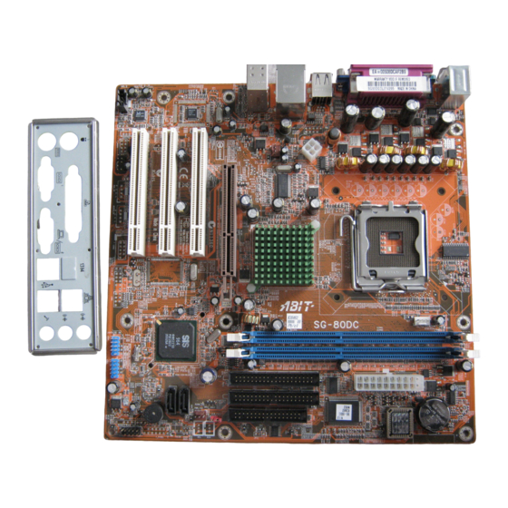
Page 7: Motherboard Layout
1.2 Motherboard Layout SG-80DC... - Page 8 SG-80DC...
-
Page 9: Hardware Setup
2.1 Choosing a Computer Chassis • This motherboard carries an mATX form factor of 244 x 244 mm. Choose a chassis big enough to install this motherboard. • As some features for this motherboard are implemented by cabling connectors on the motherboard to indicators and switches or buttons on the chassis, make sure your chassis supports all the features required. -
Page 10: Checking Jumper Settings
(reserved for future use) will leave it at OPEN position. SHORT For 3-pin jumper, pin 1~2 or pin 2~3 can be shorted by plugging the jumper cap in. Pin 1~2 SHORT them OPEN Pin 2~3 SHORT OPEN SG-80DC... -
Page 11: Cmos Memory Clearing Header And Backup Battery
4. For incorrect CPU ratio/clock settings in the BIOS, press <Del> key to enter the BIOS setup menu right after powering on system. 5. Set the CPU operating speed back to its default or an appropriate value. 6. Save and exit the BIOS setup menu. SG-80DC... - Page 12 5. Enter the BIOS setup menu. Reconfigure the setup parameters if necessary. CAUTION: ※ Danger of explosion may arise if the battery is incorrectly renewed. ※ Renew only with the same or equivalent type recommended by the battery manufacturer. ※ Dispose of used batteries according to the battery manufacturer’s instructions. SG-80DC...
-
Page 13: Connecting Chassis Components
These connectors each provide power to the cooling fans installed in your system. • CPU_FAN: Power connector for CPU cooling fan • SYS_FAN: System Fan Power Connector • PWR_FAN: Auxiliary Fan Power Connector ※ These fan connectors are not jumpers. DO NOT place jumper caps on these connectors. SG-80DC... -
Page 14: Front Panel Switches & Indicators Headers
A wrong orientation will only cause the LED not lighting, but a wrong connection of the switches could cause system malfunction. Definition HD LED + HD LED - RESET RESET Reserved Definition Message LED + Message LED - Power Switch Power Switch SG-80DC... -
Page 15: Installing Hardware
2.5 Installing Hardware ※ DO NOT scratch the motherboard when installing hardware. An accidentally scratch of a tiny surface-mount component may seriously damage the motherboard. ※ In order to protect the contact pins, please pay attention to these notices: 1. A maximum 20 cycles of CPU installation is recommended. - Page 16 PUT ON the cap after operation or testing. 6. Lower the plate onto the CPU package. Engage the load lever while gently pressing down the load plate. 7. Secure the lever with the hook under retention tab. SG-80DC...
- Page 17 ※ A higher fan speed will be helpful for better airflow and heat-dissipation. Nevertheless, stay alert to touch any heatsink since the high temperature generated by the working system is still possible. SG-80DC...
-
Page 18: Ddr Memory Slots
2.5.2 DDR Memory Slots This motherboard provides two 184-pin DDR DIMM slots for un-buffered and non-ECC modules, memory size expansible up to 2GB (DDR400). DIMM Total System Memory Power off the computer and unplug the AC power cord before installing or removing memory modules. -
Page 19: Floppy And Ide Disk Drive Connectors
※ Make sure to configure the “Master” and “Slave” relation before connecting two drives by one single ribbon cable. The red line on the ribbon cable must be aligned with pin-1 on both the IDE port and the hard-drive connector. SG-80DC 2-11... -
Page 20: Serial Ata Connectors
1. Attach either end of the signal cable to the SATA connector on motherboard. Attach the other end to SATA device. 2. Attach the SATA power cable to the SATA device and connect the other end from the power supply. 2-12 SG-80DC... -
Page 21: Accelerated Graphics Port Slot
2.5.5 Accelerated Graphics Port Slot This slot supports an optional AGP graphics card up to AGP 8X/4X mode. ※ This motherboard does not support 3.3V AGP cards. Use only 1.5V or 0.8V AGP cards. 2.5.6 PCI Add-on Slots These slots provide the connection of add-on cards that comply with PCI specifications. -
Page 22: Connecting Optional Devices
2.6 Connecting Optional Devices 2.6.1 Additional USB 2.0 Port Headers Besides the 4x USB 2.0 ports located at rear I/O part, this motherboard also features 2x more USB 2.0 headers onboard. Each header supports 2x additional USB 2.0 ports by connecting bracket or cable to the rear I/O panel or the front-mounted USB ports of your chassis. -
Page 23: Front Panel Audio Connection Header
AUD_MIC_BIAS AUD_VCC Filtered AUD_F_R AUD_RET_R REVD AUD_F_L AUD_RET_L SG-80DC Function Front Panel Microphone input signal Ground used by Analog Audio Circuits Microphone Power +5V used by Analog Audio Circuits Right Channel audio signal to Front Panel Right Channel Audio signal to Return from Front... -
Page 24: Connecting I/O Devices
2.7 Connecting I/O Devices The rear I/O part of this motherboard provides the following I/O ports: • Mouse: PS/2 mouse connector. • Keyboard: PS/2 keyboard connector. • LPT1: Parallel port connector. • COM1: Serial port connector. • VGA1: Monitor signal connector. -
Page 25: Bios Setup
3. BIOS Setup This motherboard provides a programmable EEPROM that you can update the BIOS utility. The BIOS (Basic Input/Output System) is a program that deals with the basic level of communication between processor and peripherals. Use the BIOS Setup program only when installing motherboard, reconfiguring system, or prompted to “Run Setup”. - Page 26 SG-80DC...
-
Page 27: Driver & Utility
4. Driver & Utility The “Driver & Utility CD” that came packed with this motherboard contains drivers, utilities and software applications required for its basic and advanced features. Place the “Driver & Utility CD” into the CD-ROM drive in your system. The following installation auto-run screen appears. - Page 28 SG-80DC...
-
Page 29: Appendix
5.1 Troubleshooting (How to Get Technical Support?) 5.1.1 Q & A Q: Do I need to clear the CMOS before I use a new motherboard to assemble my new computer system? Yes, we highly recommend that you clear the CMOS before installing a new motherboard. Please move the CMOS jumper from its default 2-3 position to 1-2 for a few seconds, and then back. - Page 30 See the next page for a blank Technical Support Form, or visit our website to fill in the form on line (http://www.abit.com.tw/page/en/contact/technical.php). Q. Is the motherboard dead? Do I need to return it to where I bought from or go through an RMA process? After you had gone through the troubleshooting procedures, yet the problem still exists, or you find an evident damage on the motherboard.
-
Page 31: Technical Support Form
5.1.2 Technical Support Form Country: First name: Last Name: Subject: Motherboard: BIOS Version: CPU: Memory brand: Memory size: Memory configuration: Graphics card: Graphics driver version: Power supply maker: Power supply wattage: Storage devices: Optical devices: Other devices: Operating system: Problem description: SG-80DC... - Page 32 ABIT Computer Corporation http://www.abit.com.tw Rev. 1.00...