Table of Contents
Advertisement
IN9 32X
IN9 32X
Motherboard
Socket 775
User's Manual
About this Manual:
This user's manual contains all the information you may
need for setting up this motherboard. To read the user's
manual of PDF format (readable by
the "Driver & Utility CD" into the CD-ROM drive in your
system. The auto-run screen will appear, click the
"Manual" tab to enter its submenu. If not, browse the
root directory of the CD-ROM via the File Manager, and
double click the "AUTORUN" file.
-MAX
Adobe
Reader), place
IN9 32X-MAX:
NVIDIA nForce 680i SLI
NVIDIA nForce 590 SLI MCP
IN9 32X:
NVIDIA nForce 680i LT SLI
NVIDIA nForce 570 SLI MCP
FSB 1333 MHz
Dual Channel DDR2 800
Triple PCI-E X16 Slots
Dual Gigabit LAN
8x SATA 3Gb/s including 2x
external SATA Connectors
USB 2.0 / IEEE1394
7.1-Channel HD Audio
abit uGuru™ Technology
abit Silent OTES™ Technology
External CMOS Clearing
Switch
Quick Power & Reset Button
Vista HW Ready
Advertisement
Table of Contents

Related Manuals for Abit IN9 32X


Summary of Contents for Abit IN9 32X
- Page 1 User’s Manual About this Manual: This user’s manual contains all the information you may need for setting up this motherboard. To read the user’s manual of PDF format (readable by Adobe the “Driver & Utility CD” into the CD-ROM drive in your system.
- Page 2 No part of this manual may be reproduced, transmitted or transcribed without the expressed written permission of the manufacturer and authors of this manual. If you do not properly set the motherboard settings, causing the motherboard to malfunction or fail, we cannot guarantee any responsibility.
-
Page 3: Table Of Contents
2. BIOS Setup... 2-1 ™ 2.1 μGuru Utility ... 2-2 2.1.1 OC Guru ... 2-2 2.1.2 ABIT EQ... 2-5 2.2 Standard CMOS Features... 2-11 2.3 Advanced BIOS Features ... 2-13 2.4 Advanced Chipset Features... 2-16 2.5 Integrated Peripherals ... 2-18... - Page 4 3.4 Silicon Image 3132 SATA Driver... 3-3 3.5 AirPace Wi-Fi Wireless Driver ... 3-4 3.6 USB 2.0 Driver ... 3-4 3.7 abit μGuru ... 3-5 3.8 Build NVRaid Floppy Disk Under Windows Environment ... 3-6 3.9 Build SIL3132 SATA Floppy Disk Under Windows Environment... 3-7 3.10 Build SIL3132 RAID Floppy Disk Under Windows Environment ...
- Page 5 5.1 POST Code Definitions... 5-1 5.1.1 AWARD POST Code Definitions... 5-1 5.1.2 AC2005 POST Code Definitions... 5-4 5.2 Troubleshooting (How to Get Technical Support?)... 5-5 5.2.1 Q & A ... 5-5 5.2.2 Technical Support Form... 5-8 5.2.3 Contact Information... 5-9 IN9 32X/IN9 32X-MAX...
- Page 6 IN9 32X/IN9 32X -MAX...
-
Page 7: Hardware Setup
EE / Duo & Pentium Dual Core / EE / D / 4 processor • Supports FSB 1333MHz Chipset • IN9 32X-MAX: NB: NVIDIA nForce 680i SLI SB: NVIDIA nForce 590 SLI MCP • IN9 32X: NB: NVIDIA nForce 680i LT SLI... -
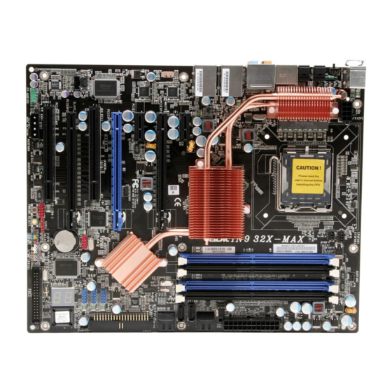
Page 8: Motherboard Layout
※ mainly based on model “IN9 32X-MAX”, unless specifically stated. For model “IN9 32X”, still you may refer to “IN9 32X-MAX”. They both have the same location and definition in headers, connectors, and jumpers, except a different chipset heatsink assembly. -
Page 9: Choosing A Computer Chassis
Most chassis have alternatives for I/O shield located at the rear panel. Make sure the I/O shield of the chassis matches the I/O port configuration of this motherboard. You can find an I/O shield specifically designed for this motherboard in its package. -
Page 10: Checking Jumper Settings
The C.C. POST Code appears when either the external “EZ-CCMOS1” switch or ※ the internal “CCMOS1” jumper is not set to its normal position. SHORT OPEN Pin 1~2 SHORT IN9 32X/IN9 32X -MAX OPEN Pin 2~3 SHORT... - Page 11 Danger of explosion may arise if the battery is incorrectly renewed. ※ Renew only with the same or equivalent type recommended by the battery ※ manufacturer. Dispose of used batteries according to the battery manufacturer’s instructions. ※ IN9 32X/IN9 32X-MAX...
-
Page 12: Connecting Chassis Components
This connector supplies power to CPU. The system will not start without connecting power to this one. ATX4P1: Auxiliary 12V Power Connector This connector provides an auxiliary power source for devices added on PCI Express slots. IN9 32X/IN9 32X -MAX... -
Page 13: Front Panel Switches & Indicators Headers
Connects to the Suspend LED cable (if there is one) of chassis front panel. • PWR (Pin 6, 8): Connects to the Power Switch cable of chassis front panel. • PLED (Pin 16, 18, 20): Connects to the Power LED cable of chassis front panel. IN9 32X/IN9 32X-MAX... -
Page 14: Fan Power Connectors
These connectors each provide power to the cooling fans installed in your system. • CPUFAN1: CPU Fan Power Connector • SYSFAN1: System Fan Power Connector • AUXFAN1~4: Auxiliary Fan Power Connector These fan connectors are not jumpers. DO NOT place jumper caps on these ※ connectors. IN9 32X/IN9 32X -MAX... -
Page 15: Additional Cooling Fan For Nb Heatsink
To attach an additional chipset cooling fan for model Inside the motherboard package you can find a pair of retention clips. These retention clips are used to fasten an additional cooling-fan attached onto the north bridge heatsink to blow away the heatwave radiated from the heatsink. -
Page 16: Installing Hardware
1.7 Installing Hardware DO NOT scratch the motherboard when installing hardware. An accidental ※ scratch of a tiny surface-mount component may seriously damage the motherboard. In order to protect the contact pins, please pay attention to these notices: ※ 1. A maximum 20 cycles of CPU installation is recommended. - Page 17 ※ Nevertheless, stay alert to not touch any heatsink since a high temperature generated by the working system is still possible. IN9 32X/IN9 32X-MAX 8. Place the heatsink and fan assembly onto the socket. Align the four fasteners toward the four mounting holes on the motherboard.
-
Page 18: Ddr2 Memory Slots
DIMM module. Static electricity can damage the electronic components of the computer or ※ optional boards. Before starting these procedures, ensure that you are discharged of static electricity by touching a grounded metal object briefly. 1-12 IN9 32X/IN9 32X -MAX... -
Page 19: Pci Express X16 Add-On Slots (Install Graphics Card)
These slots support the connections of graphics cards that comply with PCI Express specifications. This motherboard provides triple PCI-Express X16 slots: One PCIE graphics card installation (Normal Mode): Insert your PCIE graphics card into [PCIEXP1] (MASTER) slot. The [PCIEXP3] slot supports up to X8 bandwidth only. ※ IN9 32X/IN9 32X-MAX 1-13... - Page 20 The following illustration is served for DEMO only. All the devices, including the ※ motherboard, the graphics cards, the SLI Bridge Connector, or the SLI bracket, may not be exactly the same type, shape, or model as the one you bought.
-
Page 21: Connecting Peripheral Devices
Make sure to configure the “Master” and “Slave” relation before connecting ※ two drives by one single ribbon cable. The red line on the ribbon cable must be aligned with pin-1 on both the IDE port and the hard-drive connector. IN9 32X/IN9 32X-MAX 1-15... -
Page 22: Serial Ata Connectors
Attach the SATA power cable to the SATA device and connect the other end from the power supply. The motherboard in this photo is served for DEMO only, and may not be the ※ same type or model as the one described in this user’s manual. -
Page 23: Additional Usb 2.0 Port Headers
Each header supports 1x additional IEEE1394 port by connecting bracket or cable to the rear I/O panel or the front-mounted IEEE1394 port of your chassis. Make sure the connecting cable bears the same pin assignment. ※ IN9 32X/IN9 32X-MAX Pin Assignment Data0 - Data0 +... -
Page 24: Internal Audio Connectors
Pin 4 “AVCC” of this header. 1-18 Pin Assignment (HD AUDIO) MIC2 L AGND MIC2 R AVCC FRO-R MIC2_JD F_IO_SEN FRO-L LINE2_JD IN9 32X/IN9 32X -MAX Pin Assignment (AC’97 AUDIO) MIC In MIC Power Line Out (R) Line Out (L) - Page 25 The audio driver is originally configured to support HD Audio. For AC’97 audio connection, you may: Right-click the “Realtek HD Audio Manager” icon system tray. Click “Audio I/O” tab, and then click “Connector Settings”. Click “Disabled front panel jack detection”, and then click “OK” to confirm. IN9 32X/IN9 32X-MAX 1-19...
-
Page 26: S/Pdif Output Connection Header
This header provides the S/PDIF output connection to your add-on HDMI VGA card. 1.8.8 PCI and PCI Express X1 Slot Install PCI Express X1 cards into slots “PCIE1” and/or “PCIE2”. Install PCI cards into slots “PCI1” and/or “PCI2”. 1-20 Pin Assignment VCC (5V) S/PDIF Out Ground IN9 32X/IN9 32X -MAX... -
Page 27: Guru Panel Connection Header
1.8.9 Guru Panel Connection Header This header is reserved for connecting abit’s exclusive Guru Panel. For more information, please refer to the included Guru Panel Installation Guide. IN9 32X/IN9 32X-MAX 1-21... -
Page 28: Onboard Indicators And Buttons
This LED device also displays the “POST” Code of AC2005, an “uGuru” chipset developed exclusively by abit. The decimal point lights up during the AC2005 POST action. ※ See Appendix for both AWARD and AC2005 POST Code definitions. 1-22 IN9 32X/IN9 32X -MAX... -
Page 29: Power Source Indicators
SLI_PWR1: This LED lights up when the “ATX4P1” connector is NOT connected with power. 1.9.3 Onboard Buttons • PWRSW1: Push this button to power on the system. • RESET1: Push this button to reset the system. IN9 32X/IN9 32X-MAX 1-23... -
Page 30: Connecting Rear Panel I/O Devices
1.10 Connecting Rear Panel I/O Devices The rear I/O part of this motherboard provides the following I/O ports: • Mouse: Connects to PS/2 mouse. • Keyboard: Connects to PS/2 keyboard. • EZ-CCMOS1: This switch enables clearing the CMOS memory without uncovering the system chassis. -
Page 31: Bios Setup
2. BIOS Setup This motherboard provides a programmable EEPROM so that you can update the BIOS utility. The BIOS (Basic Input/Output System) is a program that deals with the basic level of communication between processor and peripherals. Use the BIOS Setup program only when installing motherboard, reconfiguring system, or prompted to “Run Setup”. -
Page 32: Μguru ™ Utility
This item displays the CPU model name installed on this motherboard. Frequency This item displays the processor speed of the CPU installed on this motherboard. SLI-Ready Memory This item selects the SPD profile for SLI-Ready memories. The configuration options may vary depending on the type of module you installed. - Page 33 There will be no guaranty for the settings beyond specification. Any damage of ※ any component on this motherboard or peripherals resulting therein is not our responsibility. FSB <QDR> This item selects the external clock frequency. Due to the specification limit of the CPU you installed, the speed you set over its standard bus speed is supported, but not guaranteed.
-
Page 34: Cpu Vtt Voltage
DDR2 REF Voltage NB DDR2 REF Voltage CPU VTT Voltage NB Voltage SB Voltage HyperTransport Voltage μGuru Utility v1.00C @ 2.66GHz Item Help ► Auto Detect 1.3500 V 1.850 V 1.20 V 1.35 V 1.50 V 1.20 V IN9 32X/IN9 32X -MAX... -
Page 35: Abit Eq
:Move Enter:Select +/-/PU/PD:Value F8:OC On The Fly F10:Save ESC:Exit These items display the power cycle statistics for each element. 2.1.2 ABIT EQ Click right-arrow <→> key to switch from OC Guru setup menu to ABIT EQ setup menu: ABIT EQ ABIT EQ Beep Control LED Effect Control ►... -
Page 36: Temperature Monitoring
39°C/102°F ( ) 135° 54 A 54 A Beep Beep Enable Temp. 75°C/167°F ° C/149°F 55°C/131°F ° C/275°F (*) 125°C/257°F ° C/275°F (*) 125°C/257°F ° C/275°F (*) 125°C/257°F ° C/275°F (*) 125°C/257°F ° C/275°F (*) 125°C/257°F F10:Save ESC:Exit IN9 32X/IN9 32X -MAX... - Page 37 High/Low Limit These items set the high and low voltage limit. The value of high limit must be set above the one of low limit. ※ IN9 32X/IN9 32X-MAX μGuru Utility v1.00C Reading Shutdown Beep...
-
Page 38: Fan Speed Monitoring
Low Limit These items set the low limit of fan speed. μGuru Utility v1.00C Reading Shutdown Enable 2440 RPM Beep Enable Limit 300 RPM 300 RPM 300 RPM 300 RPM 300 RPM 300 RPM F10:Save ESC:Exit IN9 32X/IN9 32X -MAX... - Page 39 This item selects the reference point for taking temperature among the available options of CPU, SYS, and PWM Temperature, but there is only one “CPU Temperature” item to choose for the “CPU FanEQ Control”. IN9 32X/IN9 32X-MAX μGuru Utility v1.00C Press Enter Press Enter μGuru Utility v1.00C...
- Page 40 These items set the high and low voltage limit that you want to provide the fan with. The value of high limit must be set above the one of low limit. ※ 2-10 μGuru Utility V1.00C Enabled SYS Temperature 40°C/104°F 30°C/86°F 12.0 V 8.0 V Disabled Disabled Item Help ►►► F10:Save ESC:Exit IN9 32X/IN9 32X -MAX...
-
Page 41: Standard Cmos Features
Access Mode Capacity Cylinder Head Precomp Landing Zone Sector :Move Enter:Select +/-/PU/PD:Value F10:Save ESC:Exit F1:General Help F5: Previous Values IN9 32X/IN9 32X-MAX Standard CMOS Features Fri, Mar 9 2007 12 : 34 : 56 None None None None None None... - Page 42 This item determines whether the system stops if an error is detected during system boot-up. [All Errors]: The system-boot will stop whenever the BIOS detect a non-fatal error. [No Errors]: The system-boot will not stop for any error detected. 2-12 IN9 32X/IN9 32X -MAX...
-
Page 43: Advanced Bios Features
Quick Power On Self Test When set to [Enabled], this item speeds up the Power On Self Test (POST) after powering on the system. The BIOS shorten or skip some check during the POST. IN9 32X/IN9 32X-MAX Advanced BIOS Features Enabled... -
Page 44: Cpu Feature
This option enables or disables to unlock the multiplier factor for the processor you installed. This item appears only with certain unlocked processors. ※ 2-14 CPU Feature Auto Enabled Enabled Disabled Enabled Enabled Enabled F6: Fail-Safe Defaults Item Help F7: Optimized Defaults IN9 32X/IN9 32X -MAX... - Page 45 But by doing this, you will have to reset all previously set options. MPS Version Ctrl For OS This item specifies which version of MPS (Multi-Processor Specification) this motherboard will use. Leave this item at its default setting. Delay For HDD (Secs) This item allows the BIOS to support some old or special IDE devices by prolonging this delay time.
-
Page 46: Advanced Chipset Features
Disabled F6: Fail-Safe Defaults Memory Timing Setting Setting Current Value Auto Auto Auto Auto Auto Auto Auto(2) Auto(15) Auto(3) Auto(7) Auto 7.8uS Auto F6: Fail-Safe Defaults Item Help F7: Optimized Defaults Item Help F7: Optimized Defaults IN9 32X/IN9 32X -MAX... - Page 47 LinkBoost Select [Enable] to guarantee a higher clock with certified GPU. ECC Control Options: [Disabled], [Auto]. ECC Uncorrectable Options: [Disabled], [No Notify], [MCERR], [NMI], [SCI], [SMI]. ECC Correctable Options: [Disabled], [No Notify], [MCERR], [NMI], [SCI], [SMI]. IN9 32X/IN9 32X-MAX 2-17...
-
Page 48: Integrated Peripherals
Press Enter PCI Slot V1.1+V2.0 Auto Auto Auto Disabled Enabled Enabled Enabled Enabled F6: Fail-Safe Defaults OnChip IDE/RAID Device Press Enter Press Enter F6: Fail-Safe Defaults Item Help F7: Optimized Defaults Item Help F7: Optimized Defaults IN9 32X/IN9 32X -MAX... -
Page 49: Ide Function Setup
- SATA3 RAID x - SATA4 RAID x - SATA5 RAID x - SATA6 RAID :Move Enter:Select +/-/PU/PD:Value F10:Save ESC:Exit F1:General Help F5: Previous Values IN9 32X/IN9 32X-MAX IDE Function Setup Enabled Enabled All Enabled F6: Fail-Safe Defaults F7: Optimized Defaults... -
Page 50: Usb Keyboard Support
This item selects the mode for devices connected through eSATA1 ports. SATA Option ROM This item allows you to use the boot ROM of onboard SATA to boot up system. Onboard 1394 Controller This option enables or disables the IEEE 1394 controller. 2-20 IN9 32X/IN9 32X -MAX... -
Page 51: Power Management Setup
(Resume On Ring/LAN) prior to the date and time set in these items, the system will give priority to the incoming calls or network instead. IN9 32X/IN9 32X-MAX Power Management Setup S3(Suspend To RAM) -
Page 52: Kb Power On Password
If the system’s power is off when AC power failure occurs, it will remain off when power returns. If the system’s power is on when AC power failure occurs, the system will power-on when power returns. 2-22 IN9 32X/IN9 32X -MAX... -
Page 53: Pnp/Pci Configurations
IRQ-4 assigned to IRQ-5 assigned to IRQ-7 assigned to IRQ-10 assigned to IRQ-11 assigned to :Move Enter:Select +/-/PU/PD:Value F10:Save ESC:Exit F1:General Help F5: Previous Values IN9 32X/IN9 32X-MAX PnP/PCI Configurations Auto(ESCD) Press Enter Disbaled 4096 F6: Fail-Safe Defaults F7: Optimized Defaults... -
Page 54: Load Fail-Safe Defaults
This option protects the BIOS configuration or restricts access to the computer itself. 2.11 Save & Exit Setup This option saves your selections and exits the BIOS setup menu. 2.12 Exit Without Saving This option exits the BIOS setup menu without saving any changes. 2-24 IN9 32X/IN9 32X -MAX... -
Page 55: Driver & Utility
The screen shots in this chapter are snapped from model “IN9 32X-MAX”. ※ For model “IN9 32X”, the installation items remain the same, except a different background) 3.1 CD-ROM AUTORUN To run the CD-ROM automatically: Place the “Driver-&-Utility CD”... -
Page 56: Nvidia Nforce Chipset Driver
The installation screen appears. Follow the prompts on the screen to complete installation. After restarting the system, right-click the Sound Manager icon located at the desktop shortcut. Click item “Sound Manager”. The Realtek HD Audio Manager appears. IN9 32X/IN9 32X -MAX... -
Page 57: Silicon Image 3132 Sata Driver
“eSATA1”. To install this program: Click on the [Drivers] tab in the installation menu screen. Click the [Silicon Image 3132 SATA Driver] item. The installation screen appears. Follow the prompts on the screen to complete installation. IN9 32X/IN9 32X-MAX... -
Page 58: Airpace Wi-Fi Wireless Driver
Follow the prompts on the screen to complete installation. 3.6 USB 2.0 Driver There is no need to install this driver for Windows 2000 with Service Pack 4, ※ Windows XP with Service Pack 1, or their later version. IN9 32X/IN9 32X -MAX... -
Page 59: Abit Μguru
3.7 abit μGuru The abit μGuru combined with the optional Guru Panel allows you to access and select system performance of your system while playing games, listening music, browsing Internet or office applications in full screen with no need to stop or close the running application. -
Page 60: Build Nvraid Floppy Disk Under Windows Environment
This procedure is necessary if you want to install operating system to a RAID configuration connected among “SATA1~SATA6” connectors: Prepare a 3.5” floppy disk drive and connect it to “FDC1” connector on this motherboard. Start install operating system. Insert this driver disk into floppy disk drive when the screen instruction prompts you to install a third-party SCSI or RAID driver. -
Page 61: Build Sil3132 Sata Floppy Disk Under Windows Environment
This procedure is necessary if you want to install operating system to a SATA configuration connected between “eSATA1” connectors: Prepare a 3.5” floppy disk drive and connect it to “FDC1” connector on this motherboard. Start install operating system. Insert this driver disk into floppy disk drive when the screen instruction prompts you to install a third-party SCSI or RAID driver. -
Page 62: Build Sil3132 Raid Floppy Disk Under Windows Environment
This procedure is necessary if you want to install operating system to a RAID configuration connected between “eSATA1” connectors: Prepare a 3.5” floppy disk drive and connect it to “FDC1” connector on this motherboard. Start install operating system. Insert this driver disk into floppy disk drive when the screen instruction prompts you to install a third-party SCSI or RAID driver. -
Page 63: Build A Driver Disk Under Dos Environment
Enter and select the BIOS menu “Advanced BIOS Features”. Configure the option “First Boot Device” to “CD-ROM” by accessing the BIOS menu “Save & Exit Setup”. Restart the system. The system will now boot from CD, and enter the ABIT Boot Manager, the following options appear (0) Boot From First HDD... - Page 64 3-10 IN9 32X/IN9 32X -MAX...
-
Page 65: Multilingual Quick Installation Guide
Ce “Guide d’Installation rapide ” contient seulement l information de base dont vous pouvez avoir besoin lors de l’installation de votre carte mère abit. Pour des opérations plus avancées, vous devez vous reporter à la version complète. Précautions d’installation du matériel •... -
Page 66: Deutsch//Kurze Installationsanleitung
4.2 Deutsch//Kurze Installationsanleitung Diese “Kurze Installationsanleitung” enthält nur die grundlegenden Hardwareinformationen, die Sie zur Installation Ihres abit-Motherboards benötigen. Details finden Sie im ausführlichen Handbuch. Vorsichtsmaßnahmen beim Einrichten der Hardware Vor Installation des Motherboards und Ändern von • Einstellungen müssen Sie immer die Stromversorgung ausschalten und den Stecker von der Steckdose abziehen. -
Page 67: Italiano//Guida All'installazione Rapida
4.3 Italiano//Guida all’installazione rapida Questa “Guida all’installazione rapida” contiene solamente le informazioni di base sull’hardware necessarie all’installazione della scheda madre abit. Fare riferimento alla versione completa della guida per eseguire le operazioni avanzate. Precauzioni sull’installazione dell’hardware • Spegnere sempre l’unità e scollegare il cavo d’alimentazione dalla presa CA prima di installare la scheda o modificare qualsiasi impostazione. -
Page 68: Español//Guía Rápida De Instalación
4.4 Español//Guía rápida de instalación Esta “Guía de instalación rápida” contiene solamente la información básica sobre el hardware que puede necesitar durante la instalación de la placa base abit. Para conocer el funcionamiento avanzado, es necesario consultar la versión completa. -
Page 69: Português//Guia De Instalação Rápida
Este “Guia de instalação rápida” contém apenas informação essencial sobre o hardware e necessária à instalação da sua placa principal abit. Para mais informações, terá de consultar a versão integral deste guia. Normas de segurança a ter em conta durante a montagem do hardware •... -
Page 70: Русский//Краткое Руководство По Установке
4.6 Русский//Краткое руководство по установке В “Кратком руководстве по установке” содержится только основная информация о техническом обеспечении, которая вам может понадобиться при установке материнской платы abit. Описание дополнительных операций вы найдете в полной версии руководства. Предостережения по установке технического обеспечения •... -
Page 71: Eesti//Kiirpaigaldusjuhend
4.7 Eesti//Kiirpaigaldusjuhend Käesolev “Kiirpaigaldusjuhend” sisaldab ainult abit-emaplaadi paigaldamiseks vajalikku riistvaraalast põhiteavet. Edasijõudnud kasutamiseks tuleb teil ikkagi pöörduda täisversiooni poole. Ettevaatusabinõud riistvara paigaldamisel Enne emaplaadi paigaldamist või ümberseadistamist lülitage • alati eelnevalt toide välja ning lahutage toitejuhe vooluvõrgust. Enne plaadi antistaatilisest kotist välja võtmist maandage •... -
Page 72: Latviski//Ātrās Instalēšanas Instrukcija
4.8 Latviski//Ātrās instalēšanas instrukcija Šī “Ātrās instalēšanas instrukcija” ietver tikai pamata norādes iekārtai, kas nepieciešamas, instalējot abit mātesplati. Pilnīgākai darbībai nepieciešams iegūt instrukcijas paplašināto variantu. Piesardzības pasākumi iekārtas uzstādīšanā Vienmēr pirms plates pievienošanas vai jebkuru uzstādījumu • izmaiņām izslēdziet strāvas padevi un atvienojiet vadu no maiņstrāvas barošanas avota. -
Page 73: Lietuvių//Trumpas Instaliavimo Vadovas
4.9 Lietuvių//Trumpas instaliavimo vadovas Šiame “Trumpame instaliavimo vadove” pateikta tik esminė informacija apie techninę įrangą, kurios jums gali prireikti instaliuojant pagrindinę plokštę abit. Papildomų operacijų aprašymą rasite pilnoje vadovo versijoje. Atsargumo priemonės instaliuojant techninę įrangą Prieš instaliuodami plokštę ar keisdami parametrus visuomet •... -
Page 74: Polski//Instrukcja Szybkiej Instalacji
4.10 Polski//Instrukcja szybkiej instalacji Ta “Instrukcja szybkiej instalacji” zawiera tylko podstawowe informacje dotyczące sprzętu, wymagane podczas instalacji płyty głównej abit. Przy zaawansowanych operacjach, niezbędne będzie skorzystanie z kompletnej wersji instrukcji. Środki bezpieczeństwa przy instalacji sprzętu Przed instalacją płyty lub zmianą jakichkolwiek ustawień, •... -
Page 75: Magyar//Gyorstelepítési Útmutató
4.11 Magyar//Gyorstelepítési útmutató Ez a “Gyorstelepítési útmutató” csak azt az alapvető hardver információt tartalmazza, amely az abit alaplap telepítéséhez szükséges. Az előrehaladott üzemeltetéshez, továbbra is a teljes útmutatót kell használnia. Hardver beállítási óvintézkedések Minding kapcsolják ki a tápot ás áramtalanítsák a készüléket •... -
Page 76: Türkçe//Hızlı Kurulum Kılavuzu
4.12 Türkçe//Hızlı Kurulum Kılavuzu Bu “Hızlı Kurulum Kılavuzu”, abit anakartınızı takmanızda gerekebilecek sadece temel donanım bilgisini içermektedir. İleri işlemler için daha geniş olan tam versiyonuna başvurmanız gerekecektir. Donanım Kurmada Alınacak Önlemler Anakartı takmadan veya ayarları değiştirmeden önce daima • güç beslemeyi kapatarak güç kablosunu elektrik prizinden çekin. - Page 77 دﻟﻴﻞ اﻟﺘﺮآﻴﺐ اﻟﺴﺮﻳﻊ اﻟﻠﻐﺔ اﻟﻌﺮﺑﻴﺔ 4.13 IN9 32X/IN9 32X-MAX 4-13...
- Page 78 راهﻨﻤﺎﯼ ﻧﺼﺐ ﺳﺮﻳﻊ ﻓﺎرﺳﯽ 4.14 4-14 IN9 32X/IN9 32X -MAX...
-
Page 79: 日本語//クイックインストールガイド
シャーシコンポーネントの接続 ATX 電源装置: [ATXPWR1]、[ATX12V1] ファンコネクタ: [CPUFAN1], [SYSFAN1], [AUXFAN1], [NBFAN1] 前面パネルコネクタ: [FPIO1] • [HLED]: HDD LED ケーブルに接続 • [RST]: リセットスイッチケーブルに接続 IN9 32X/IN9 32X-MAX • [SPKR]: システムスピーカーケーブルに接続 • [SLED]: サスペンド LED ケーブルに接続 • [PWR]: 電源スイッチケーブルに接続 • [PLED]: 電源 LED ケーブルに接続 追加 USB ポートヘッダ: [FP-USB1]、[FP-USB2] 追加... -
Page 80: 한국어//빠른 설치 가이드
4.16 한국어//빠른 설치 가이드 본 “빠른 설치 가이드”는 빅빔 abit 메인보드 설치에 필요한 중요한 하드웨어 정보만을 포함하고 있습니다. 보다 상세한 정보 및 과정은 사용자 설명서를 참고하시기 바랍니다. 하드웨어 설치시 주의사항 • 메인보드 설치 또는 설정을 변경하시기 전에는 항상 전 원을 끄고, AC 콘센트를 제거하시기... -
Page 81: Bahasa Malaysia//Panduan Pemasangan Ringkas
4.17 Bahasa Malaysia//Panduan Pemasangan Ringkas “Panduan Pemasangan Ringkas” ini hanya mengandungi maklumat perkakasan asas yang anda mungkin perlu semasa memasang papan induk abit anda. Untuk pengendalian lanjutan, anda perlu rujuk ke versi lengkapnya. Langkah Berjaga-jaga bagi Penyediaan Perkakasan Sentiasa matikan bekalan kuasa dan keluarkan kord kuasa •... -
Page 82: ไทย//คู ่ ม ื อ การติ ด ตั ้ ง อย่ า งย่ อ
เป็ น เพี ย งข้ อ มู ล พื ้ น ฐานที ่ จ ำเป็ น ใน การติ ด ตั ้ ง แผงวงจรหลั ก abit ของคุ ณ เท่ า นั ้ น กรุ ณ า อ่ า นข้ อ มู ล ในการติ ด ตั ้ ง และใช้ ง านในระดั บ สู ง ขึ ้ น จาก... -
Page 83: 繁體中文
Pentium Dual Core / EE / D / 4 處理器的 LGA775 插座 • 支援 1333MHz 前端匯流排 晶片組 • IN9 32X-MAX: NB: NVIDIA nForce 680i SLI SB: NVIDIA nForce 590 SLI MCP • IN9 32X: NB: NVIDIA nForce 680i LT SLI SB: NVIDIA nForce 590 SLI MCP 記憶體... -
Page 84: 快速安裝略說
Keyboard:連接 PS/2 鍵盤。 • LPT1:連接印表機或其他支援平行通訊協定的裝 • 置。 COM1:連接外接數據機、滑鼠或其他支援序列通訊 • 協定的裝置。 OPT-IN1:本插座提供透過光纖連接到數位多媒體裝 • 置的 S/PDIF 輸入。 OPT-OUT1:本插座提供透過光纖連接到數位多媒體 • 裝置的 S/PDIF 輸出。 AUDIO1: 7.1 聲道音效輸入/輸出連接。 • IEEE1394:連接 IEEE1394 通訊協定裝置。 • LAN1:連接區域網路。 • USB1/USB2:連接 USB 裝置,例如掃描器、數位喇 • 叭、顯示器、滑鼠、鍵盤、集線器、數位相機或搖 桿等。 IN9 32X/IN9 32X -MAX... -
Page 85: 简体中文
Pentium Dual Core / EE / D / 4 处理器的 LGA775 插座 • 支持 1333MHz 前端总线 芯片组 • IN9 32X-MAX: NB: NVIDIA nForce 680i SLI SB: NVIDIA nForce 590 SLI MCP • IN9 32X: NB: NVIDIA nForce 680i LT SLI SB: NVIDIA nForce 590 SLI MCP 内存... -
Page 86: 快速安装略说
• Keyboard:连接 PS/2 键盘。 • LPT1:连接打印机或其它支持并行通信协议的设 • 备。 COM1:连接外部调制解调器、鼠标或支持串行通信 • 协议的其它设备。 OPT-IN1:此连接器通过光纤提供 S/PDIF 输入连接, • 用于连接数码多媒体设备。 OPT-OUT1:此连接器通过光纤提供 S/PDIF 输出连 • 接,用于连接数码多媒体设备。 AUDIO1:7.1 声道音效输入/输出连接。 • IEEE1394:连接支持 IEEE1394 协议的设备。 • LAN1:连接到局域网。 • USB1/USB2:连接 USB 设备,如扫描仪、数码扬声 • 器、监视器、鼠标、键盘、集线器、数码相机、操 纵杆等。 IN9 32X/IN9 32X -MAX... -
Page 87: Appendix
Prepare BIOS resource map for PCI & PnP use. If ESCD is valid, take into consideration of the ESCD’s legacy information. Early PCI Initialization: -Enumerate PCI bus number. -Assign memory & I/O resource -Search for a valid VGA device & VGA BIOS, and put it into C000:0 IN9 32X/IN9 32X-MAX... - Page 88 2. Auto assign ports to onboard COM ports if the corresponding item in Setup is set to “AUTO” 1. Initialize floppy controller 2. Set up floppy related fields in 40:hardware Detect & install all IDE devices: HDD, LS120, ZIP, CDROM … IN9 32X/IN9 32X -MAX...
- Page 89 Update keyboard LED & typematic rate 1. Build MP table 2. Build & update ESCD 3. Set CMOS century to 20h or 19h 4. Load CMOS time into DOS timer tick 5. Build MSIRQ routing table Boot attempt (INT 19h) IN9 32X/IN9 32X-MAX E8POST.ASM starts...
-
Page 90: Ac2005 Post Code Definitions
Either the external “EZ-CCMOS1” switch or the internal “CCMOS1” jumper is not C.C. set to its normal position. F.0. Button reset F.1. SoftMenu reset F.2. Power on sequence timeout F.3. Power off sequence timeout Power On Sequence Power Off Sequence Others IN9 32X/IN9 32X -MAX... -
Page 91: Troubleshooting (How To Get Technical Support?)
5.2 Troubleshooting (How to Get Technical Support?) 5.2.1 Q & A Q: Do I need to clear the CMOS before I use a new motherboard to assemble my new computer system? A: Yes, we highly recommend that you clear the CMOS before installing a new motherboard. - Page 92 Motherboard: Type in the model name and revision number of your motherboard. Example: AA8XE REV: 1.00 • BIOS Version: Type in the BIOS version of your motherboard. (You can find it on the screen during the POST sequence.) • CPU: Type in the brand name and the speed (MHz) of your CPU. (Illustrate the over-clocking status if you had done so.)
- Page 93 See the next page for a blank Technical Support Form, or visit our website to fill in the form on line (http://www.abit.com.tw/page/en/contact/technical.php). Q. Is the motherboard dead? Do I need to return it to where I bought from or go through an RMA process? A: After you have gone through the troubleshooting procedures, yet the problem still exists, or you find an evident damage on the motherboard, please contact our RMA center.
-
Page 94: Technical Support Form
First name: Last Name: Subject: Motherboard: BIOS Version: CPU: Memory brand: Memory size: Memory configuration: Graphics card: Graphics driver version: Power supply maker: Power supply wattage: Storage devices: Optical devices: Other devices: Operating system: Problem description: IN9 32X/IN9 32X -MAX... -
Page 95: Contact Information
Fax: 1-510-623-1092 Website: http://www.abit-usa.com Latin America: r aymond@abit-usa.com RMA Center: http://rma.abit-usa.com UK, Ireland Universal ABIT UK Co. Ltd. Unit 3, 24-26 Boulton Road, Stevenage, Herts SG1 4QX, United Kingdom Tel: 44-1438-228888 Fax: 44-1438-226333 For technical support and RMA return: technical@abitcomputer.co.uk returns@abitcomputer.co.uk... - Page 96 P/N: 4310-0000-76 Rev. 4.00...