Table of Contents
Advertisement
Motherboard
Socket 775
User's Manual
For more information:
www.abit.com.tw
FP-IN9 SLI
LGA775 ATX
NB: NVIDIA nForce 650i SLI
SB: NVIDIA nForce 430 SLI
MCP
1066MHz FSB
Dual DDR2 800
NVIDIA Gigabit LAN
4x SATA 3Gb/s
7.1-Channel HD Audio
Silent OTES™ Technology
FPIO LED Lighting
Quick Power & Reset Button
Vista HW Ready
Advertisement
Table of Contents

Related Manuals for Abit Fatal1ty FP-IN9 SLI


Summary of Contents for Abit Fatal1ty FP-IN9 SLI
- Page 1 Motherboard Socket 775 User’s Manual For more information: www.abit.com.tw FP-IN9 SLI LGA775 ATX NB: NVIDIA nForce 650i SLI SB: NVIDIA nForce 430 SLI 1066MHz FSB Dual DDR2 800 NVIDIA Gigabit LAN 4x SATA 3Gb/s 7.1-Channel HD Audio Silent OTES™ Technology FPIO LED Lighting Quick Power &...
- Page 2 No part of this manual may be reproduced, transmitted or transcribed without the expressed written permission of the manufacturer and authors of this manual. If you do not properly set the motherboard settings, causing the motherboard to malfunction or fail, we cannot guarantee any responsibility.
- Page 3 Introduction FATAL1TY STORY Who knew that at age 19, I would be a World Champion PC gamer. When I was 13, I actually played competitive billiards in professional tournaments and won four or five games off guys who played at the highest level.
- Page 4 FATAL1TY PARTNERS This is just the beginning. We’re already in development for several new products, and I’m really grateful to all my Fatal1ty partners for helping make my dreams a reality. I know there is a business side to all of this, but for me the true reward is making products that are so good I can win with them –...
-
Page 5: Table Of Contents
Contents 1. Hardware Setup ... 1-1 1.1 Specifications... 1-1 1.2 Motherboard Layout ... 1-2 1.3 Choosing a Computer Chassis ... 1-3 1.4 Installing Motherboard ... 1-3 1.5 Checking Jumper Settings... 1-4 1.5.1 CMOS Memory Clearing Header and Backup Battery ... 1-4 1.6 Connecting Chassis Components ... - Page 6 3.2 nVidia nForce Chipset Driver ... 3-2 3.3 Realtek HD Audio Driver ... 3-2 3.4 USB 2.0 Driver ... 3-3 3.5 ABIT EQ (The Hardware Doctor Utility)... 3-4 3.6 FlashMenu (BIOS Update Utility) ... 3-5 3.7 Build NVRaid Floppy Disk Under Windows Environment ... 3-6 3.8 Build A Driver Disk Under DOS Environment ...
-
Page 7: Hardware Setup
• 1x 7.1-channel Audio connector • 4x USB 2.0 connectors • 1x RJ-45 Gigabit LAN connector abit Engineered ™ • abit Silent OTES Technology • FPIO LED Lighting • Quick Power & Reset Button RoHS • 100% Lead-free process and RoHS... -
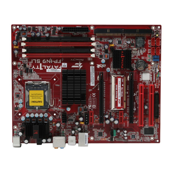
Page 8: Motherboard Layout
1.2 Motherboard Layout FP-IN9 SLI... -
Page 9: Choosing A Computer Chassis
Most chassis have alternatives for I/O shield located at the rear panel. Make sure the I/O shield of the chassis matches the I/O port configuration of this motherboard. You can find an I/O shield specifically designed for this motherboard in its package. -
Page 10: Checking Jumper Settings
1.5 Checking Jumper Settings • For a 2-pin jumper, plug the jumper cap on both pins will make it CLOSE (SHORT). Remove the jumper cap, or plug it on either pin (reserved for future use) will leave it at OPEN position. •... - Page 11 CMOS Backup Battery: An onboard battery saves the CMOS memory to keep the BIOS information stays on even after disconnected your system with power source. Nevertheless, this backup battery exhausts after some five years. Once the error message like “CMOS BATTERY HAS FAILED” or “CMOS checksum error”...
-
Page 12: Connecting Chassis Components
1.6 Connecting Chassis Components 1.6.1 ATX Power Connectors These connectors provide the connection from an ATX power supply. As the plugs from the power supply fit in only one orientation, find the correct one and push firmly down into these connectors. -
Page 13: Front Panel Switches & Indicators Headers
1.6.2 Front Panel Switches & Indicators Headers This header is used for connecting switches and LED indicators on the chassis front panel. Watch the power LED pin position and orientation. The mark “+” align to the pin in the figure below stands for positive polarity for the LED connection. -
Page 14: Fan Power Connectors
1.6.3 FAN Power Connectors These connectors each provide power to the cooling fans installed in your system. • CPUFAN1: CPU Fan Power Connector • SYSFAN1: System Fan Power Connector • AUXFAN1~2: Auxiliary Fan Power Connector These fan connectors are not jumpers. DO NOT place jumper caps on these ※... -
Page 15: Installing Hardware
1.7 Installing Hardware DO NOT scratch the motherboard when installing hardware. An accidental ※ scratch of a tiny surface-mount component may seriously damage the motherboard. In order to protect the contact pins, please pay attention to these notices: ※ 1. A maximum 20 cycles of CPU installation is recommended. - Page 16 1-10 8. Place the heatsink and fan assembly onto the socket. Align the four fasteners toward the four mounting holes on the motherboard. 9. Press each of the four fasteners down into the mounting holes. Rotate the fastener clock-wise to lock the heatsink and fan assembly into position.
-
Page 17: Ddr2 Memory Slots
1.7.2 DDR2 Memory Slots To reach the performance of Dual Channel DDR2, the following rules must be obeyed: • For a 2-DIMM dual-channel installation: Populate DIMM modules of the same type and size on slots [DIMM1]+[DIMM3], or slots [DIMM2]+[DIMM4]. • For a 4-DIMM dual-channel installation: Populate 2 DIMM modules of the same type and size on slots [DIMM1]+[DIMM3], and another 2 DIMM modules of the same type and size on slots [DIMM2]+[DIMM4]. - Page 18 To install system memory: Power off the computer and unplug the AC power cord before installing or removing memory modules. Locate the DIMM slot on the board. Hold two edges of the DIMM module carefully, keep away from touching its connectors.
-
Page 19: Pci Express X16 Add-On Slots (Install Graphics Card)
1.7.3 PCI Express X16 Add-on Slots (Install Graphics Card) These slots support the connections of graphics cards that comply with PCI Express specifications. This motherboard provides two PCI-Express X16 slots: One PCIE graphics card installation (Normal Mode): Insert your PCIE graphics card into [PCIEXP1] (Master) slot. - Page 20 The following illustration is served for DEMO only. All the devices, including the ※ motherboard, the graphics cards, the SLI Bridge Connector, or the SLI bracket, may not be exactly the same type, shape, or model as the one you have at hand.
- Page 21 4. Push the card down into the retention slot till both the retention arms firmly hold the card into position. Also, keep away from touching the connectors (Golden Fingers). 5. Insert two identical SLI-ready graphics cards into both [PCIEXP1] (Master) and [PCIEXP2] (Slave) slots.
-
Page 22: Connecting Peripheral Devices
1.8 Connecting Peripheral Devices 1.8.1 Floppy and IDE Disk Drive Connectors The FDC1 connector connects up to two floppy drives with a 34-wire, 2-connector floppy cable. Connect the single end at the longer length of ribbon cable to the FDC1 on the board, the two connectors on the other end to the floppy disk drives connector. -
Page 23: Serial Ata Connectors
Attach the SATA power cable to the SATA device and connect the other end from the power supply. The motherboard in this photo is served for DEMO only, and may not be the ※ same type or model as the one described in this user’s manual. -
Page 24: Additional Usb 2.0 Port Headers
1.8.3 Additional USB 2.0 Port Headers Each header supports 2x additional USB 2.0 ports by connecting bracket or cable to the rear I/O panel or the front-mounted USB ports of your chassis. Make sure the connecting cable bears the same pin assignment. ※... -
Page 25: Internal Audio Connectors
Audio, yet for AC’97 Audio CODEC connection, you must carefully check the pin assignment before connecting from the front panel module. An incorrect connection may cause malfunction or even damage the motherboard. Please do not connect the “Ground” cable or “USB VCC” cable ※... - Page 26 Driver Configuration for AC’97 audio connection: The audio driver is originally configured to support HD Audio. For AC’97 audio connection, you may: Right-click the “Realtek HD Audio Manager” icon system tray. Click “Audio I/O” tab, and then click “Connector Settings”. Click “Disabled front panel jack detection”, and then click “OK”...
-
Page 27: Pci And Pci Express X1 Slot
1.8.6 PCI and PCI Express X1 Slot Install PCI Express X1 cards into slots “PCIE1” and/or “PCIE2”. Install PCI cards into slots “PCI1” and/or “PCI2”. FP-IN9 SLI 1-21... -
Page 28: Onboard Indicators And Buttons
1.9 Onboard Indicators and Buttons 1.9.1 LED Indicators • 5VSB/FPIO1 Lighter: These LEDs light up when the power supply is connected with power source. • VCC: This LED lights up when the system power is on. • SLI_LED1: This LED lights up when the “SLI Switch Card” is working under “SLI” Mode. 1.9.2 Onboard Buttons •... -
Page 29: Connecting Rear Panel I/O Devices
1.10 Connecting Rear Panel I/O Devices The rear I/O part of this motherboard provides the following I/O ports: • Mouse: Connects to PS/2 mouse. • Keyboard: Connects to PS/2 keyboard. • OPT-OUT1: This connector provides an S/PDIF-Out connection through optical fiber to digital multimedia devices. - Page 30 For more information: www.abit.com.tw 1-24 FP-IN9 SLI...
-
Page 31: Bios Setup
2. BIOS Setup This motherboard provides a programmable EEPROM so that you can update the BIOS utility. The BIOS (Basic Input/Output System) is a program that deals with the basic level of communication between processor and peripherals. Use the BIOS Setup program only when installing motherboard, reconfiguring system, or prompted to “Run Setup”. -
Page 32: Softmenu Setup
This item displays the CPU model name installed on this motherboard. Frequency This item displays the processor speed of the CPU installed on this motherboard. SLI-Ready Memory This item selects the SPD profile for SLI-Ready memories. The configuration options may vary depending on the type of module you installed. -
Page 33: Cpu Vtt Voltage
FSB:Memory Ratio This item selects the CPU-to-DRAM ratio. Options: [Auto], [1:1], [5:4], [3:2], [Sync Mode]. FSB (QDR) This item selects the front side bus frequency. Due to the specification limit of the CPU you installed, the speed you set over ※... -
Page 34: Standard Cmos Features
2.2 Standard CMOS Features Phoenix – AwardBIOS CMOS Setup Utility Date (mm:dd:yy) Time (hh:mm:ss) ► IDE Channel 1 Master ► IDE Channel 1 Slave ► IDE Channel 2 Master ► IDE Channel 2 Slave ► SATA Channel 1 ► SATA Channel 2 ►... - Page 35 IDE HDD Auto-Detection This item allows you to detect the parameters of IDE drives by pressing <Enter> key. The parameters will be shown on the screen automatically. IDE Channel 1 Maste/Slaver, IDE Channel 2 Master/Slave, SATA Channel 1~4 When set to [Auto], the BIOS will automatically check what kind of IDE or SATA hard drive you are using.
- Page 36 This item displays the amount of base memory installed in the system. The value of the base memory is typically 640K for systems with 640K or more memory size installed on the motherboard. Extended Memory This item displays the amount of extended memory detected during system boot-up.
-
Page 37: Advanced Bios Features
2.3 Advanced BIOS Features Phoenix – AwardBIOS CMOS Setup Utility Quick Power on Self Test ► CPU Feature ► Hard Disk Boot Priority First Boot Device Second Boot Device Third Boot Device Boot Other Device Boot Up Floppy Seek Boot Up NumLock Status Security Option MPS Version Ctrl For OS Delay For HDD (Secs) - Page 38 Thermal Control This option enables or disables the thermal monitoring. Limit CPUID MaxVal When set to [Enabled], this item limits the CPUID maximum value to 3, which is usually required for older OS like Windows NT4.0. Leave this item at its default [Disabled] settings for OS like Windows XP. Execute Disable Bit This item appears only for certain processors with the Execute Disable Bit (XD bit) feature.
- Page 39 But by doing this, you will have to reset all previously set options. MPS Version Ctrl For OS This item specifies which version of MPS (Multi-Processor Specification) this motherboard will use. Leave this item at its default setting. Delay For HDD (Secs) This item allows the BIOS to support some old or special HDD devices by prolonging this delay time.
-
Page 40: Advanced Chipset Features
2.4 Advanced Chipset Features Phoenix – AwardBIOS CMOS Setup Utility ► Memory Timing Setting SLI Broadcast Aperture LDT Frequency :Move Enter:Select +/-/PU/PD:Value F10:Save ESC:Exit F1:General Help F5: Previous Values Memory Timing Setting Click <Enter> key to enter its submenu: Phoenix – AwardBIOS CMOS Setup Utility Parameters Memory Timing Setting x tCL (CAS Latency) - Page 41 tRRD tWTR tREF Back to Advanced Chipset Features Setup Menu SLI Broadcast Aperture Options: [Disabled], [Auto]. LDT Frequency Options: [1X], [2X] , [3X], [4X], [5X], [6X], [7X], [8X]. FP-IN9 SLI 2-11...
-
Page 42: Integrated Peripherals
2.5 Integrated Peripherals Phoenix – AwardBIOS CMOS Setup Utility ► OnChip IDE/SATA Device Init Display First OnChip USB - USB Keyboard Support - USB Mouse Support OnChip Audio Controller OnChip LAN Controller - OnChip LAN Boot ROM Onboard FDD Controller :Move Enter:Select +/-/PU/PD:Value F10:Save ESC:Exit F1:General Help F5: Previous Values OnChip IDE/SATA Device... - Page 43 IDE/SATA Function Setup Click <Enter> key to enter its submenu: Phoenix – AwardBIOS CMOS Setup Utility IDE 1 Controller IDE 2 Controller IDE DMA Transfer Access OnChip SATA Controller :Move Enter:Select +/-/PU/PD:Value F10:Save ESC:Exit F1:General Help F5: Previous Values IDE 1 Controller This item allows you to enable or disable the IDE1 controller.
-
Page 44: Raid Configuration
RAID Configuration Click <Enter> key to enter its submenu: Phoenix – AwardBIOS CMOS Setup Utility RAID Function x - SATA1 RAID x - SATA2 RAID x - SATA3 RAID x - SATA4 RAID :Move Enter:Select +/-/PU/PD:Value F10:Save ESC:Exit F1:General Help F5: Previous Values RAID Function This item allows you to enable or disable the RAID function. - Page 45 OnChip LAN Controller This option enables or disables the LAN controller. OnChip LAN Boot ROM This item allows you to use the boot ROM (instead of a disk drive) to boot-up the system and access the local area network directly. Onboard FDD Controller This option enables or disables the floppy disk controller.
-
Page 46: Power Management Setup
2.6 Power Management Setup Phoenix – AwardBIOS CMOS Setup Utility ACPI Suspend Type - USB Resume from S3 Power Button Function Wake Up by PME# of PCI Wake Up by OnChip LAN Wake Up by Alarm X - Day of Month Alarm X - Time(hh:mm:ss) Alarm Power On Function X - KB Power On Password... -
Page 47: Kb Power On Password
Day of Month Alarm [0]: This option power-on the system everyday according to the time set in the “Time (hh:mm:ss) Alarm” item. [1-31]: This option selects a date you would like the system to power-on. The system will power-on on the date set, and the time set in the “Time (hh:mm:ss) Alarm” item. Time (hh:mm:ss) Alarm This item sets the time you would like the system to power-on. -
Page 48: Pnp/Pci Configurations
2.7 PnP/PCI Configurations Phoenix – AwardBIOS CMOS Setup Utility Resources Controlled By X - IRQ Resources PCI/VGA Pallete Snoop ** PCI Express relative items ** Maximum Payload Size :Move Enter:Select +/-/PU/PD:Value F10:Save ESC:Exit F1:General Help F5: Previous Values Resources Controlled By This item configures all of the boot and Plug-and-Play compatible devices. - Page 49 [Disabled]: MPEG ISA/VESA VGA cards do not work with PCI/VGA. Maximum Payload Size This item sets the maximum TLP payload size for the PCI Express devices. FP-IN9 SLI 2-19...
-
Page 50: Pc Health Status
2.8 PC Health Status Phoenix – AwardBIOS CMOS Setup Utility CPU Shutdown Temperature CPU Warning Temperature FAN Fail Alarm Selectable Shutdown When FAN Fail CPU FanEQ Control - CPU FanEQ Target Temperature - CPU FanEQ Temp. Tolerance - CPU FanEQ Start Control - CPU FanEQ Stop Control SYS FanEQ Control - SYS FanEQ Reference Temp. - Page 51 CPU FanEQ Temp. Tolerance This item sets the temperature tolerance range for the item “CPU FanEQ Target Temp.”. CPU FanEQ Start Control This item sets the speed ratio for the 4-pin CPU fan assembly connected at “CPUFAN1” fan power connector to start running. CPU FanEQ Stop Control This item sets the lowest speed ratio for the 4-pin CPU fan assembly connected at “CPUFAN1”...
-
Page 52: Load Fail-Safe Defaults
This option protects the BIOS configuration or restricts access to the computer itself. 2.12 Save & Exit Setup This option saves your selections and exits the BIOS setup menu. 2.13 Exit Without Saving This option exits the BIOS setup menu without saving any changes. For more information: www.abit.com.tw 2-22 FP-IN9 SLI... -
Page 53: Driver & Utility
• [Utility]: Click to enter the utilities installation menu. • [abit Utility]: Click to enter the installation menu of utilities exclusively developed by abit. • Browse CD]: Click to browse the contents of this “Driver-&-Utility CD”. • Close]: Click to exit this installation menu. -
Page 54: Nvidia Nforce Chipset Driver
3.2 nVidia nForce Chipset Driver To install this program: Click on the [Drivers] tab in the installation menu screen. Click the [nVidia nForce Chipset Driver] item. The installation screen appears. Follow the prompts on the screen to complete installation. Please install this nVidia nForce ※... -
Page 55: Usb 2.0 Driver
Click the [Audio I/O] tab. Click the pull down menu to select the channel configuration. Click [OK] button to apply the Audio I/O settings and exit. 3.4 USB 2.0 Driver There is no need to install this driver for Windows 2000 with Service Pack 4, ※... -
Page 56: Abit Eq (The Hardware Doctor Utility)
The [ABITEQ] is a self-diagnostic system designed to protect PC Hardware by monitoring critical items of Power Supply Voltage, CPU & System Fans Speed, and CPU & System Temperature. To install this utility: Click on the [abit Utility] tab in the installation menu screen. Click the [ABITEQ] item. The following screen appears. -
Page 57: Flashmenu (Bios Update Utility)
With one click of BIOS updating, users can flash their BIOS more easily and in less time. To install this utility: Click on the [abit Utility] tab in the installation menu screen. Click the [FlashMenu] item. The following screen appears. -
Page 58: Build Nvraid Floppy Disk Under Windows Environment
This procedure is necessary if you want to install operating system to a RAID configuration connected among “SATA1~SATA4” connectors: Prepare a 3.5” floppy disk drive and connect it to “FDC1” connector on this motherboard. Start install operating system. Insert this driver disk into floppy disk drive when the screen instruction prompts you to install a third-party SCSI or RAID driver. -
Page 59: Build A Driver Disk Under Dos Environment
Enter and select the BIOS menu “Advanced BIOS Features”. Configure the option “First Boot Device” to “CD-ROM” by accessing the BIOS menu “Save & Exit Setup”. Restart the system. The system will now boot from CD, and enter the ABIT Boot Manager, the following options appear (0) Boot From First HDD... - Page 60 For more information: www.abit.com.tw FP-IN9 SLI...
-
Page 61: Multilingual Quick Installation Guide
Ce “Guide d’Installation rapide ” contient seulement l information de base dont vous pouvez avoir besoin lors de l’installation de votre carte mère abit. Pour des opérations plus avancées, vous devez vous reporter à la version complète. Précautions d’installation du matériel •... -
Page 62: Deutsch//Kurze Installationsanleitung
4.2 Deutsch//Kurze Installationsanleitung Diese “Kurze Installationsanleitung” enthält nur die grundlegenden Hardwareinformationen, die Sie zur Installation Ihres abit-Motherboards benötigen. Details finden Sie im ausführlichen Handbuch. Vorsichtsmaßnahmen beim Einrichten der Hardware Vor Installation des Motherboards und Ändern von • Einstellungen müssen Sie immer die Stromversorgung ausschalten und den Stecker von der Steckdose abziehen. -
Page 63: Italiano//Guida All'installazione Rapida
4.3 Italiano//Guida all’installazione rapida Questa “Guida all’installazione rapida” contiene solamente le informazioni di base sull’hardware necessarie all’installazione della scheda madre abit. Fare riferimento alla versione completa della guida per eseguire le operazioni avanzate. Precauzioni sull’installazione dell’hardware • Spegnere sempre l’unità e scollegare il cavo d’alimentazione dalla presa CA prima di installare la scheda o modificare qualsiasi impostazione. -
Page 64: Español//Guía Rápida De Instalación
4.4 Español//Guía rápida de instalación Esta “Guía de instalación rápida” contiene solamente la información básica sobre el hardware que puede necesitar durante la instalación de la placa base abit. Para conocer el funcionamiento avanzado, es necesario consultar la versión completa. -
Page 65: Português//Guia De Instalação Rápida
Este “Guia de instalação rápida” contém apenas informação essencial sobre o hardware e necessária à instalação da sua placa principal abit. Para mais informações, terá de consultar a versão integral deste guia. Normas de segurança a ter em conta durante a montagem do hardware •... -
Page 66: Русский//Краткое Руководство По Установке
4.6 Русский//Краткое руководство по установке В “Кратком руководстве по установке” содержится только основная информация о техническом обеспечении, которая вам может понадобиться при установке материнской платы abit. Описание дополнительных операций вы найдете в полной версии руководства. Предостережения по установке технического обеспечения •... -
Page 67: Eesti//Kiirpaigaldusjuhend
4.7 Eesti//Kiirpaigaldusjuhend Käesolev “Kiirpaigaldusjuhend” sisaldab ainult abit-emaplaadi paigaldamiseks vajalikku riistvaraalast põhiteavet. Edasijõudnud kasutamiseks tuleb teil ikkagi pöörduda täisversiooni poole. Ettevaatusabinõud riistvara paigaldamisel Enne emaplaadi paigaldamist või ümberseadistamist lülitage • alati eelnevalt toide välja ning lahutage toitejuhe vooluvõrgust. Enne plaadi antistaatilisest kotist välja võtmist maandage •... -
Page 68: Latviski//Ātrās Instalēšanas Instrukcija
4.8 Latviski//Ātrās instalēšanas instrukcija Šī “Ātrās instalēšanas instrukcija” ietver tikai pamata norādes iekārtai, kas nepieciešamas, instalējot abit mātesplati. Pilnīgākai darbībai nepieciešams iegūt instrukcijas paplašināto variantu. Piesardzības pasākumi iekārtas uzstādīšanā Vienmēr pirms plates pievienošanas vai jebkuru uzstādījumu • izmaiņām izslēdziet strāvas padevi un atvienojiet vadu no maiņstrāvas barošanas avota. -
Page 69: Lietuvių//Trumpas Instaliavimo Vadovas
4.9 Lietuvių//Trumpas instaliavimo vadovas Šiame “Trumpame instaliavimo vadove” pateikta tik esminė informacija apie techninę įrangą, kurios jums gali prireikti instaliuojant pagrindinę plokštę abit. Papildomų operacijų aprašymą rasite pilnoje vadovo versijoje. Atsargumo priemonės instaliuojant techninę įrangą Prieš instaliuodami plokštę ar keisdami parametrus visuomet •... -
Page 70: Polski//Instrukcja Szybkiej Instalacji
4.10 Polski//Instrukcja szybkiej instalacji Ta “Instrukcja szybkiej instalacji” zawiera tylko podstawowe informacje dotyczące sprzętu, wymagane podczas instalacji płyty głównej abit. Przy zaawansowanych operacjach, niezbędne będzie skorzystanie z kompletnej wersji instrukcji. Środki bezpieczeństwa przy instalacji sprzętu • Przed instalacją płyty lub zmianą jakichkolwiek ustawień, należy zawsze wyłączyć... -
Page 71: Magyar//Gyorstelepítési Útmutató
4.11 Magyar//Gyorstelepítési útmutató Ez a “Gyorstelepítési útmutató” csak azt az alapvető hardver információt tartalmazza, amely az abit alaplap telepítéséhez szükséges. Az előrehaladott üzemeltetéshez, továbbra is a teljes útmutatót kell használnia. Hardver beállítási óvintézkedések Minding kapcsolják ki a tápot ás áramtalanítsák a készüléket •... -
Page 72: Türkçe//Hızlı Kurulum Kılavuzu
4.12 Türkçe//Hızlı Kurulum Kılavuzu Bu “Hızlı Kurulum Kılavuzu”, abit anakartınızı takmanızda gerekebilecek sadece temel donanım bilgisini içermektedir. İleri işlemler için daha geniş olan tam versiyonuna başvurmanız gerekecektir. Donanım Kurmada Alınacak Önlemler Anakartı takmadan veya ayarları değiştirmeden önce daima • güç beslemeyi kapatarak güç kablosunu elektrik prizinden çekin. - Page 73 دﻟﻴﻞ اﻟﺘﺮآﻴﺐ اﻟﺴﺮﻳﻊ اﻟﻠﻐﺔ اﻟﻌﺮﺑﻴﺔ 4.13 FP-IN9 SLI 4-13...
- Page 74 راهﻨﻤﺎﯼ ﻧﺼﺐ ﺳﺮﻳﻊ ﻓﺎرﺳﯽ 4.14 4-14 FP-IN9 SLI...
-
Page 75: 日本語//クイックインストールガイド
4.15 日本語//クイックインストールガイド この「クイックインストールガイド」には、abit マ ザーボードを取り付けるときに必要となるハードウ ェアの基本情報のみが含まれています。詳細な操作 については、その完全版を参照してください。 ハードウェアのセットアップに関する注意事項 • ボードを取り付けたり設定を変更するときは、 事前に 電源装置をオフにし、AC コンセントからプラグを必 ず抜いてください。 • 静電気防止バッグからボードを取り外す前に、 静電気 安全リストストラップを着用して、 正しくアースして ください。 • ボードは、端を持つようにしてください。コンポーネ ントには触れないでください。 • モジュールの接点や IC チップには触れないでくださ い、 • ボードはアースされた静電気防止面またはボードに 付属する静電気防止バッグの上に置いてください。 ボードのシャーシへの取り付け このマザーボードのコンピュータシャーシは、以下の点 を満たしている必要があります。 • このマザーボードのフォームファクタに適合するこ と。 • シャーシのインジケータやスイッチとマザーボード 上のすべてのケーブルコネクタをサポートすること。... -
Page 76: 한국어//빠른 설치 가이드
4.16 한국어//빠른 설치 가이드 본 “빠른 설치 가이드”는 빅빔 abit 메인보드 설치에 필요한 중요한 하드웨어 정보만을 포함하고 있습니다. 보다 상세한 정보 및 과정은 사용자 설명서를 참고하시기 바랍니다. 하드웨어 설치시 주의사항 • 메인보드 설치 또는 설정을 변경하시기 전에는 항상 전 원을 끄고, AC 콘센트를 제거하시기... -
Page 77: Bahasa Malaysia//Panduan Pemasangan Ringkas
4.17 Bahasa Malaysia//Panduan Pemasangan Ringkas “Panduan Pemasangan Ringkas” ini hanya mengandungi maklumat perkakasan asas yang anda mungkin perlu semasa memasang papan induk abit anda. Untuk pengendalian lanjutan, anda perlu rujuk ke versi lengkapnya. Langkah Berjaga-jaga bagi Penyediaan Perkakasan Sentiasa matikan bekalan kuasa dan keluarkan kord kuasa •... -
Page 78: ไทย//คู ่ ม ื อ การติ ด ตั ้ ง อย่ า งย่ อ
เป็ น เพี ย งข้ อ มู ล พื ้ น ฐานที ่ จ ำเป็ น ใน การติ ด ตั ้ ง แผงวงจรหลั ก abit ของคุ ณ เท่ า นั ้ น กรุ ณ า อ่ า นข้ อ มู ล ในการติ ด ตั ้ ง และใช้ ง านในระดั บ สู ง ขึ ้ น จาก... -
Page 79: 繁體中文
• 1 個 S/PDIF 輸出接頭 • 1 個 7.1 聲道音效接頭 • 4 個 USB 2.0 接頭 • 1 個 RJ-45 Gigabit 網路接頭 abit Engineered ™ • abit Silent OTES 技術 • FPIO 照明 • 快速的電源與重置按鈕 RoHS • 100%無鉛處理與 RoHS 相容... -
Page 80: 快速安裝略說
4.19.2 快速安裝略說 本「快速安裝略說」僅包含安裝 abit 主機板時所需的 基本硬體資訊。詳細的操作方式,仍請參閱其完整的 手冊版本。 硬體安裝注意事項 • 安裝機板或變換任何設定之前,請先關閉電源並拔 掉電源插頭。 • 從抗靜電袋中取出機板前,請先戴上靜電安全手 環,以確保自己已確實接地。 • 請握住機板的邊緣。請勿接觸機板上的任何元件。 請勿接觸模組及 IC 晶片 • • 請將機板置於已接地的抗靜電平面上,或置於隨附 的抗靜電袋。 將機板安裝至機殼內 本主機板的電腦機殼應符合以下條件: • 與本主機板的規格相容。 • 機殼上的指示燈及開關支援主機板上的連接線插 座。 • 能提供足夠的電力及空間,以容納所有您想安裝的 磁碟機。 背面的 I/O 必須配合主機板上的 I/O 連接埠及擴充插 • 槽。... -
Page 81: 简体中文
• 1 个 S/PDIF 输出接头 • 1 个 7.1 声道音效接头 • 4 个 USB 2.0 接头 • 1 个 RJ-45 Gigabit 网络接头 abit Engineered ™ • abit Silent OTES 技术 • FPIO 照明 • 快速的电源与复位按钮 RoHS • 100%无铅工艺,符合 RoHS 规范... -
Page 82: 快速安装略说
4.20.2 快速安装略说 本“快速安装略说”仅包含基本的硬件信息,供您在 安装 abit 主板时进行参考。如需了解高级操作,仍请 参阅其完整的手册版本。 硬件设置㊟意事㊠ • 在安装主板或更改任何设置前,务必关闭电源并从 交流插座㆖拔掉电源线。 • 从防静电袋㆗取出主板前,应戴㆖静电安全腕带以 使您㊣确接㆞。 • 用手拿着主板的边缘。不要触摸主板㆖的任何元 件。 不要触摸模块触点和 IC 芯片。 • • 将主板放在接㆞的防静电表面㆖或者放在主板附带 的防静电袋㆗。 将主板安装到底盘㆖ 此主板的计算机底盘应符合㆘列条件: • 支持此主板的外形尺寸。 • 支持主板㆖的所㈲线缆连接器,能够连接到底盘㆖ 的指示灯和开关。 • 能够为您要安装的所㈲驱动装置提供充足的电源和 空间。 底盘后面板㆖的 I/O 模板与主板㆖的 I/O 端口和扩展 •... -
Page 83: Appendix
5.1 Troubleshooting (How to Get Technical Support?) 5.1.1 Q & A Q: Do I need to clear the CMOS before I use a new motherboard to assemble my new computer system? A: Yes, we highly recommend that you clear the CMOS before installing a new motherboard. - Page 84 Motherboard: Type in the model name and revision number of your motherboard. Example: AA8XE REV: 1.00 • BIOS Version: Type in the BIOS version of your motherboard. (You can find it on the screen during the POST sequence.) • CPU: Type in the brand name and the speed (MHz) of your CPU. (Illustrate the over-clocking status if you had done so.)
- Page 85 See the next page for a blank Technical Support Form, or visit our website to fill in the form on line (http://www.abit.com.tw/page/en/contact/technical.php). Q. Is the motherboard dead? Do I need to return it to where I bought from or go through an RMA process? A: After you have gone through the troubleshooting procedures, yet the problem still exists, or you find an evident damage on the motherboard, please contact our RMA center.
-
Page 86: Technical Support Form
5.1.2 Technical Support Form Region: E-mail: First name: Last Name: Subject: Motherboard: BIOS Version: CPU: Memory brand: Memory size: Memory configuration: Graphics card: Graphics driver version: Power supply maker: Power supply wattage: Storage devices: Optical devices: Other devices: Operating system:... -
Page 87: Universal Abit Contact Information
5.1.3 Universal ABIT Contact Information Taiwan Head Office Universal ABIT Co., Ltd. No. 323, Yang Guang St., Neihu, Taipei, 114, Taiwan Tel: 886-2-8751-3380 Fax: 886-2-8751-3381 Sales: sales@abit.com.tw Marketing: market@abit.com.tw North America, South America Universal ABIT (USA) Corporation 2901 Bayview Drive, Fremont, CA 94538, U.S.A. - Page 88 Johnathan “Fatal1ty” Wendel P/N: 4310-0000-61 Rev. 1.00...