3Com Baseline 2426-PWR Plus User Manual
3com baseline 2426-pwr plus: user guide
Hide thumbs
Also See for Baseline 2426-PWR Plus:
- Installation and user manual (108 pages) ,
- Release note (2 pages) ,
- User manual (136 pages)

Related Manuals for 3Com Baseline 2426-PWR Plus


Summary of Contents for 3Com Baseline 2426-PWR Plus
-
Page 1: User Guide
Baseline Switch 2426 PWR Plus User Guide Installationsanleitung 3C16491 www.3com.com Part No. 10015243 Rev. AA Published August 2006... - Page 2 3Com Corporation. 3Com Corporation reserves the right to revise this documentation and to make changes in content from time to time without obligation on the part of 3Com Corporation to provide notification of such revision or change.
-
Page 3: Table Of Contents
ONTENTS BOUT UIDE Conventions Documentation Comments Product Registration NTRODUCING THE ASELINE WITCH Overview of the Baseline Switch Features and Capabilities Autosensing of MDI/MDIX Connections Autonegotiating 10/100 Mbps Ports Power-over-Ethernet Capability Gigabit Combo Ports (RJ-45/SFP) Physical Features Front Panel Rear Panel Package Contents NSTALLING THE WITCH... - Page 4 Automatic IP Configuration IP Setup Backup Configuration Restore Configuration Firmware Upgrade Initialize Reboot System Access System Time SNMP Configuring VLANs VLAN Forwarding Tagged/Untagged Frames Sample VLAN Configurations Spanning Tree IGMP Snooping IGMP Query Broadcast Storm Configuring Port Settings Administration Speed/Duplex for 1000 Mbps Connections Link Aggregation Spanning Tree per Port Port Mirroring...
- Page 5 EGULATORY OTICES LOSSARY NDEX...
-
Page 7: About This Guide
BOUT UIDE This guide describes how to install your 3Com Switch and perform initial management configurations. This guide is intended for use by those responsible for installing and setting up network equipment; consequently, it assumes a basic working knowledge of LANs (Local Area Networks). -
Page 8: Documentation Comments
Questions related to technical support or sales should be directed in the first instance to your network supplier. Product Registration You can now register your Baseline Switch on the 3Com Web site to receive up-to-date information on your product: http://esupport.3com.com... -
Page 9: Introducing The Baseline Switch
NTRODUCING THE This chapter provides an overview of the features and capabilities of the 3Com Baseline Switch 2426 PWR Plus. It also identifies the contents of the Switch package and helps you get to know the physical features of the device. -
Page 10: Power-Over-Ethernet Capability
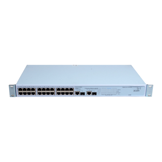
NTRODUCING THE ASELINE WITCH Power-over-Ethernet Capability The Switch provides 24 front panel RJ-45 ports that support the IEEE 802.3af Power-over-Ethernet (PoE) standard. Any 802.3af compliant device attached to a port can directly draw power from the switch over the Ethernet cable without requiring its own separate power source. - Page 11 téléphonique central privé ou public. Raccorder seulement connecteurs de données RJ-45, systèmes de réseaux de téléphonie ou téléphones de réseaux à ces prises. Il est possible de raccorder des câbles protégés ou non protégés avec des jacks protégés ou non protégés à ces prises de données.
- Page 12 NTRODUCING THE ASELINE WITCH (3) Link/Activity Status LEDs The first (top) and third row of LEDs, which are colored yellow or green, show the link, activity and speed status of the related ports: 10/100/1000BASE-T Ports Status Meaning Green The link is operating at 1000 Mbps. Yellow The link is operating at 10 or 100 Mbps.
-
Page 13: Rear Panel
Switch to the factory default settings if, for example, you have forgotten the default IP address, or forgotten your user name or password. CAUTION: 3Com recommends that you back up your configuration settings before you recover the Switch, otherwise your configuration may be lost. Refer to... -
Page 14: Package Contents
Four standard height, self-adhesive rubber pads ■ One mounting kit ■ Installation CD ■ This User Guide ■ Warranty flyer ■ The Switch is powered from the AC supply. If any of the above items are damaged or missing, contact your 3Com network supplier immediately. -
Page 15: Installing The Switch
NSTALLING THE This chapter contains information that you need to install and set up the Switch. It covers the following topics: Before You Begin ■ Positioning the Switch ■ Rack-Mounting or Free-Standing ■ Supplying Power to the Switch ■ Using SFP Transceivers ■... -
Page 16: Rack-Mounting Or Free-Standing
■ Air flow around the unit and through the vents on ■ the side of the case is not restricted (3Com recommends that you provide a minimum of 25 mm (1 in.) clearance). The air is as free from dust as possible. -
Page 17: Montagesatz Anweisungen
Insert the two screws supplied in the mounting kit and fully tighten with a suitable screwdriver. Figure 2 Rack Mounting the Unit Repeat steps 2 and 3 for the other side of the unit. Insert the unit into the 19-inch rack and secure with suitable screws (not provided). -
Page 18: Supplying Power To The Switch
Ensure that the power input to your system is clean and free from sags and surges to avoid unforeseen network outages. 3Com recommends that you install power conditioning, especially in areas prone to blackout, power dips and electrical storms. -
Page 19: Using Sfp Tranceivers
■ 3CSFP92 SFP (LX) ■ To access the latest list of approved SFP transceivers for the Switch on the 3Com Web site, enter this URL into your Internet browser: http://www.3com.com 3Com recommends using 3Com SFPs on the Switch. If you insert an SFP transceiver that is not supported, the Switch will not recognize it. -
Page 20: Removing An Sfp Transceiver
NSTALLING THE WITCH 1000BASE-LX SFP transceiver ■ Use this transceiver to connect the Switch directly to a single mode fiber-optic cable or to multi- mode fiber using a conditioned launch cable. If the SFP transceiver is faulty, it will not operate within the Switch. -
Page 21: Performing Spot Checks
Switch. Regular checks can give you an early warning of a possible failure; any problems can then be attended to when there will be least effect on users. 3Com recommends periodically checking the items listed in Table 1. Table 1 Items to Check... - Page 22 NSTALLING THE WITCH...
-
Page 23: Onnecting To The
To connect to the Web interface, you need the following: The Discovery application, which is included ■ on 3Com Baseline Switch 2426 PWR Plus CD-ROM that is supplied with your Switch A computer that is connected to the Switch ■... - Page 24 Switch, and then click Next. If the computer has only one adapter, click Next. Discovery searches the network for 3Com devices. When detection is complete, the Dis- covered Devices screen displays detected net- work devices.
-
Page 25: Logging On To The Web Interface
Figure 5 Discovered Devices Screen On the Discovered Devices screen, click Base- line Switch 2426 PWR Plus, and then click Next. The Completing the 3Com Discovery Applica- tion screen appears. Click Finish. The logon dialog box for the Web interface appears. -
Page 26: Navigating The Web Interface
3: C HAPTER ONNECTING TO THE Navigating the Web Interface The Web interface has been designed to enable you to easily perform advanced configuration tasks and view information about the Switch. Menu The menu is located on the left side of the Web interface. - Page 27 Table 1 lists the available items on the menu. Table 1 Available Menu Items Menu Item Description Device Summary Contains tabs that allow you to: Provide a summary of the Switch’s ■ basic settings and versions of current components. Set the polling interval in seconds. ■...
- Page 28 3: C HAPTER ONNECTING TO THE Menu Item Description IGMP Snooping Allows you to enable or disable IGMP snooping. IGMP Query Allows you to enable or disable IGMP query mode. Broadcast Storm Allows you to enable or disable rate limiting. Contains tabs that allow you to: Display PoE summary.
-
Page 29: Buttons
■ information for all ports. Display all cable diagnostics ■ information for a single port. Help Displays 3Com contact information and describes how to use the online help system. Log Out Allows you to securely log off the Web interface. -
Page 30: Accessing The Interface Without Using Discovery
3: C HAPTER ONNECTING TO THE Accessing the Interface Without Using Discovery The Discovery application works by automatically detecting the IP address that is assigned to the Switch, and then using that address to connect to the Web interface. If you know the Switch’s IP address, you can access the Web interface without using Discovery. -
Page 31: Onfiguring The
ONFIGURING THE This chapter provides information on how to configure the Switch’s advanced features. Topics include: Device Summary Information ■ Administration Settings ■ Configuring VLANs ■ Configuring Port Settings ■ QoS VoIP Traffic Settings ■ Security ■ Monitoring ■ Configuration Overview The Switch is shipped ready for use. - Page 32 Bootroom Version, and Hardware Version. Figure 8 Device View If you request for technical assistance from 3Com Support, you may be asked to print out the information on this screen. Polling Interval Enter the interval in seconds you would like the Switch to refresh.
-
Page 33: Administration Settings
Color Key Description of the color coding. Figure 10 Color Key Administration Settings The Administration menu includes eight administration items: IP Setup ■ Backup Configuration ■ Restore Configuration ■ Administration Settings Firmware Upgrade ■ Initialize ■ Reboot ■ System Access ■... -
Page 34: Ip Setup
169.254.1.3 The Switch repeats step 2 until an unused IP address is found. 3Com recommends using automatic IP configuration only for the initial setup. Once you gain access to the console, you should assign an IP address to the Switch (either by... -
Page 35: Backup Configuration
Figure 11 IP Settings Screen Backup Configuration To save the Switch configuration settings: Click Administration, then Backup Configuration on the menu. The Backup Configuration screen appears. Administration Settings Figure 12 Backup Configuration Click OK. You will be prompted to provide a location where the configuration file will be saved. -
Page 36: Firmware Upgrade
The file will be copied to the Switch, and once this has completed, the Switch will restart. Although the upgrade process has been designed to preserve your configuration settings, 3Com recommends that you make a backup of the configuration beforehand, in... -
Page 37: Initialize
case the upgrade process fails for any reason (for example, the connection between the computer and the Switch is lost while the new firmware is being copied to the Switch). A progress screen displays while the upgrade is taking place. The upgrade procedure can take a few minutes, and is complete when the progress bar has finished running and the Power LED... -
Page 38: System Access
Password – blank (no password) ■ To ensure that unauthorized users do not access the Web interface, 3Com recommends that you set an admin password when you first configure the Switch. Even if you do not intend to actively manage... - Page 39 Create User This page allows you to create a user and define the access level and password for that user. Figure 16 Create User Screen Administration Settings Modify User This page allows you to modify a user’s access level and password. Figure 17 Modify User Screen...
-
Page 40: System Time
4: C HAPTER ONFIGURING THE WITCH Remove User To remove a user from the Switch, click on the user name, then click Remove. Figure 18 Remove User Screen System Time Click Administration, then System Time on the menu. This screen allows you to set the system time. - Page 41 SNMP Remove ■ Summary Displays the list community access strings. Figure 20 SNMP Summary Screen Setup Enable or disable the SNMP Agent Status. Figure 21 SNMP Setup Screen Administration Settings SNMP Add This page allows you to create community strings for management access. Figure 22 SNMP Add Screen...
-
Page 42: Configuring Vlans
4: C HAPTER ONFIGURING THE WITCH SNMP Remove This page allows you to remove community strings. Figure 23 SNMP Remove Screen Configuring VLANs A virtual LAN (VLAN) is a collection of network nodes that share the same collision domain, regardless of their physical location or connection point in the network. -
Page 43: Vlan
VLAN Click Device, then VLAN on the menu. A screen appears with seven tabs that include: Setup ■ Modify VLAN ■ Modify Port ■ Rename ■ Remove ■ Port Detail ■ VLAN Detail ■ Setup Use the Setup screen to create VLANs on the Switch. - Page 44 4: C HAPTER ONFIGURING THE WITCH By default, all ports belong to VLAN 1 as an untagged member. However, they can belong to multiple VLANs as a tagged member. Also, newly created VLANs will initially have no ports associated with them. Modify VLAN Use the Modify VLAN screen to change the VLAN to which a port belongs, and configure...
- Page 45 Figure 26 Modify Port Screen Select a membership use. Available options for each port include (only one option can be associated with a single port): Not a member ■ Tagged ■ Untagged ■ Select a port to associate with the membership. Enter a VLAN to apply these changes to, then click Apply.
- Page 46 4: C HAPTER ONFIGURING THE WITCH Remove Use the Remove screen to remove a VLAN. Figure 28 Remove Screen Enter a set of VLANs or select all VLANs to add to the remove list, then click Select. From the list of selected VLANs choose a VLAN to remove, or click the Select All button to select all the VLANs.
-
Page 47: Forwarding Tagged/Untagged Frames
Figure 30 VLAN Detail Screen Forwarding Tagged/Untagged Frames Each port on the Switch is capable of passing tagged or untagged frames. The following describes how the Switch will handle tagged and untagged frames. When a port receives a tagged frame with a ■... - Page 48 4: C HAPTER ONFIGURING THE WITCH Setting Up Two VLANs on the Same Switch Figure 31 illustrates how you can set up a simple VLAN on the Switch using desktop connections. Figure 31 Desktop VLAN Configuration If you want to add ports 1, 3, and 26 to VLAN2 (as shown in Figure 31), so that the ports on...
-
Page 49: Spanning Tree
Figure 32 Tagged VLAN Configuration To set up the configuration shown in do the following: Create VLAN2 on both Switch 1 and Switch 2. You need not create VLAN1 since it exists by default. On Switch 1, set the ports that you want to be part of VLAN2 to Untagged. - Page 50 4: C HAPTER ONFIGURING THE WITCH path is maintained between spanning tree-compliant networked devices by: Disabling redundant paths when the main ■ paths are operational. Enabling redundant paths if the main paths ■ fail. Spanning tree uses a distributed algorithm to select a bridging device that serves as the root of the spanning tree network.
-
Page 51: Igmp Snooping
IGMP Snooping This switch uses IGMP (Internet Group Management Protocol) to query for any attached hosts that want to receive a specific multicast service. It identifies the ports containing hosts requesting to join the service and sends data out to those ports only. It then propagates the service request up to any neighboring multicast switch/router to ensure that it will continue to receive the multicast... -
Page 52: Poe
4: C HAPTER ONFIGURING THE WITCH A broadcast storm is an incorrect packet sent out on a network that causes most hosts to respond all at once, typically with wrong answers that start the process over again. Broadcast storms use substantial network bandwidth and may cause network time-outs. -
Page 53: Configuring Port Settings
Setup Use the Setup tab to configure the device and port PoE settings. The settings include: PoE State – Enables and disables PoE for the ■ switch. Auto – Allows the switch to manage the PoE ■ budget for selected ports. Guarantee –... - Page 54 4: C HAPTER ONFIGURING THE WITCH Summary Use the Summary tab to display Port State, Flow Control, Speed, Default VLAN ID, Link Type, or Duplex for all the ports. Figure 39 Port Administration Summary Screen Detail Use the Detail tab to display detailed port setting information for a port.
-
Page 55: Speed/Duplex For 1000 Mbps Connections
Flow Control – Enables and disables flow ■ control on the port. When flow control is enabled for the port, the Switch regulates the packet flow so that a sending device does not transmit more packets than a receiving device can process. If flow control is disabled, packets may be dropped under certain periods of high traffic. -
Page 56: Link Aggregation
4: C HAPTER ONFIGURING THE WITCH 1000 Mbps connections are always full-duplex. Half-duplex connections are only available for 10 Mbps and 100 Mbps settings. CAUTION: Before manually setting a port to full-duplex, verify that the device connected to the port is also manually set to the same speed and duplex setting. - Page 57 All ports in a trunk must be configured in an ■ identical manner, including communication mode (that is, speed, duplex mode and flow control). Four tabs are available on the Port Link Aggregation page: Summary ■ Create ■ Modify ■ Remove ■...
- Page 58 4: C HAPTER ONFIGURING THE WITCH To create a new link aggregation group: Enter a link aggregation group ID in the box field. Select the ports to add to the goup. Click Apply. Modify Use the Modify tab reassign port members to a link aggregation group.
-
Page 59: Spanning Tree Per Port
Spanning Tree per Port This administrative tool supports the configuration of the Switch to forward, or block and discard 802.1D spanning tree BPDU packets. Spanning tree is a bridge-based system for providing fault tolerance on networks and can be used to detect and disable network loops. The spanning tree ensures that the optimal path is maintained between spanning tree-compliant networked devices by:... - Page 60 4: C HAPTER ONFIGURING THE WITCH Summary Use the Summary tab to display Status, Edged Port, Link Type, Path Cost, State, or Port Priority for all the ports. Figure 46 Spanning Tree Summary Screen Detail Use the Detail tab to display detailed spanning tree information for a port.
-
Page 61: Port Mirroring
Link Type – Choose between Point-to-Point, ■ Shared, or Auto for the link type. Path Cost – The path cost is used to ■ determine the best path between devices. The path cost method is used to determine the range of values that can be assigned to each interface. -
Page 62: Statistics
4: C HAPTER ONFIGURING THE WITCH Figure 49 Port Mirroring Setup Screen To set up port mirroring: Connect a network analyzer to a port. Access the Web interface. Click Port, then Port Mirroring on the menu. The Port Monitoring Setup Screen appears. Select the port number under Monitor Port to which you want to monitor. -
Page 63: Qos Voip Traffic Settings
Click Apply. QoS VoIP Traffic Settings Using the Web interface, you can configure the Voice over Internet Protocol (VoIP) settings. The QoS VoIP Traffic Setting menu includes six tabs: Summary ■ Setup ■ Port Setup ■ Port Detail ■ OUI Summary ■... - Page 64 4: C HAPTER ONFIGURING THE WITCH You must first create a VLAN from the VLAN Setup page before you can assign and configure a Voice VLAN. Figure 52 QoS VoIP Setup Screen Port Setup Use the Port Setup tab to configure the port or trunk setting for Voice VLAN.
- Page 65 Port Detail Use the Port Detail tab to display the Voice VLAN information for selected ports. Figure 54 QoS Port Detail Screen OUI Summary Use the OUI Summary tab to display the list of Organizational Unique Identifier for a company and their description.
-
Page 66: Security
4: C HAPTER ONFIGURING THE WITCH To remove an OUI from the list: Select a Telephony OUI from the list. Click Remove. Figure 56 QoS OUI Modify Screen Security Using the Web interface, you can configure the RADIUS Client and 802.1X settings. The Security menu includes two items: RADIUS Client ■... - Page 67 Figure 57 RADIUS Client Detail Screen Configure Use the Configure tab to configure the RADIUS settings. The following parameters are available: Max Retries – Sets the number of retries of ■ sending authentication requests. Timeout – Sets the interval between sending ■...
-
Page 68: 802.1X Settings
4: C HAPTER ONFIGURING THE WITCH 802.1X Settings The IEEE 802.1X (dot1x) standard defines a port-based access control procedure that prevents unauthorized access to a network by requiring users to first submit credentials for authentication. The 802.1X settings menu includes three tabs: Summary ■... - Page 69 Figure 60 802.1X Detail Screen Setup Use the Setup tab to configure the 802.1X authenticaion settings. The following fields are available: System Authentication – Sets the global ■ setting for 802.1X. (Default: Disabled) Operation Mode – Allows single or multiple ■...
-
Page 70: Monitoring
4: C HAPTER ONFIGURING THE WITCH Reauthentication Period – Sets the time ■ period after which a connected client must be re-authenticated. (Range: 1-65535 seconds; Default: 3600 seconds) Quiet Period – Sets the time that a switch ■ port waits after the Max Request Count has been exceeded before attempting to acquire a new client. -
Page 71: Cable Diagnostics
Figure 62 Address Table Screen Cable Diagnostics The Switch provides cable diagnostic, which helps you detect and resolve issues with the attached cables. The Cable Diagnostics menu includes two tabs: Summary ■ Diagnostics ■ Monitoring Summary Use the Summary tab to display information on Test Result, Cable Fault Distance, or Last Update for every port on the switch. - Page 72 4: C HAPTER ONFIGURING THE WITCH Diagnostics Use the Diagnostics tab to display individual port information on Test Result, Cable Fault Distance, and Last Update. Figure 64 Cable Diagnostic Screen...
-
Page 73: Troubleshooting
Switch, with suggested courses of cor- rective action to take. If you encounter an issue that is not listed here and you cannot solve it, check the 3Com Knowledgebase at http://knowledgebase.3com.com contacting your local technical support representative. -
Page 74: Forgotten Password
5: T HAPTER ROUBLESHOOTING The Switch will perform automatic IP configu- ration after you reset it. See Configuration” page 33 tion. Forgotten Password If you forget the password to the Web interface after you set it, you will need to reset the Switch to regain access. - Page 75 The fiber cable is in good condition. ■ The SFP module is correctly inserted. ■ A 3Com SFP module is being used. Refer to ■ “Approved SFP Transceivers” on page 19 details. The equipment at the far end is installed and ■...
-
Page 76: If The Problem Persists
If the Problem Persists If the problem persists and the unit still does not operate successfully, contact your 3Com network supplier with the following informa- tion before returning the unit: Product number and serial number (printed ■... -
Page 77: A Obtaining Support For Your Product
Contact your authorized 3Com reseller or 3Com for a complete list of the value-added services available in your area. Troubleshoot Online You will find support tools posted on the 3Com Web site at 3Com Knowledgebase helps you troubleshoot 3Com products. This query-based interactive tool is located at http://knowledgebase.3com.com... -
Page 78: Telephone Technical Support And Repair
Details about recent configuration changes, if ■ applicable To send a product directly to 3Com for repair, you must first obtain a return authorization number (RMA). Products sent to 3Com, without authorization numbers clearly marked on the outside of the package, will be returned to the sender unopened, at the sender’s... - Page 79 Thailand 001 800 611 2000 You can also obtain support in this region using the following e-mail: apr_technical_support@3com.com Or request a repair authorization number (RMA) by fax using this number: +65 543 6348 Europe, Middle East, and Africa Telephone Technical...
- Page 80 Latin America Telephone Technical Support and Repair Antigua Barbuda AT&T +800 988 2112 Argentina Local Number 54 11 5556 3200 Argentina 0 810 444 3COM Argentina 810 44 32 66 Aruba AT&T +800 998 2112 Bahamas AT&T +800 998 2112 Barbados AT&T +800 998 2112...
-
Page 81: B Technical Information
ECHNICAL Related Standards The Baseline Switch 2426 PWR Plus has been designed to the following standards: Functional IEEE 802.3 (Ethernet), IEEE 802.3u (Fast Ethernet), IEEE 802.3ab and IEEE 802.3z (Gigabit Ethernet), IEEE 802.3x (Flow Control), IEEE 802.1D 1993 (Bridging), IEEE D802.1Q 1998 (Virtual LAN) 4096 Address... - Page 82 B: T PPENDIX ECHNICAL NFORMATION...
-
Page 83: C Safety Information
3Com Switch Family Safety and Regulatory Information manual included with this product. NFORMATION You can find the 3Com Switch Family Safety and Regulatory Information manual on the product CD-ROM that was included with your switch. You can also download the safety manual from the 3Com Web site:... - Page 84 C: S PPENDIX AFETY NFORMATION...
- Page 85 EGULATORY OTICES FCC Statement This equipment has been tested and found to comply with the limits for a Class A digital device, pursuant to Part 15 of the FCC Rules. These limits are designed to provide reasonable protection against harmful interference in a commerical environment. This equipment generates, uses and can radiate radio frequency energy and, if not installed and used in accordance with the instructions, may cause harmful interference to radio communications.
- Page 87 LOSSARY 10BASE-T The IEEE specification for 10 Mbps Ethernet over Category 3, 4 or 5 twisted pair cable. 100BASE-TX The IEEE specification for 100 Mbps Fast Ethernet over Category 5 twisted-pair cable. 1000BASE-LX IEEE 802.3z specification for Gigabit Ethernet over 9/125 micron core single-mode fiber cable.
- Page 88 LOSSARY Category 3 Cables One of five grades of Twisted Pair (TP) cabling defined by the EIA/TIA-568 standard. Category 3 is voice grade cable and can only be used in Ethernet networks (10BASE-T) to transmit data at speeds of up to 10 Mbps.
- Page 89 Full Duplex A system that allows packets to be transmitted and received at the same time and, in effect, doubles the potential throughput of a link. Half Duplex A system that allows packets to be transmitted and received, but not at the same time. Half duplex is not supported for 1000 Mbps.
- Page 90 LOSSARY switches) that cover a relatively small geographic area (usually not larger than a floor or building). LANs are characterized by high transmission speeds over short distances (up to 1000 metres). Layer 2 Data Link layer in the ISO 7-Layer Data Communications Protocol.
- Page 91 Server A computer in a network that is shared by multiple end stations. Servers provide end stations with access to shared network services such as computer files and printer queues. Small Form Factor Pluggable (SFP) Connectors are based on an open standard that enables hot swapping of various type of fiber optic and copper-based transceivers into the host equipment.
- Page 92 LOSSARY VLAN A Virtual LAN is a collection of network nodes that share the same collision domain regardless of their physical location or connection point in the network. A VLAN serves as a logical workgroup with no physical barriers, and allows users to share information and resources as though located on the same LAN.
- Page 93 NDEX Numbers 1000BASE-LX 87 1000BASE-SX 87 1000BASE-T 87 100BASE-TX 87 10BASE-T 87 auto IP configuration 33 default IP address 34 default mask 34 bandwidth 87 Baseline Switch 2848-SFP 81 category 3 cables 88 category 5 cables 88 category 5e cables 88 category 6 cables 88 client 88 configuration...
- Page 94 NDEX network analyzer 61, 62 network defined 90 password changing 38 default (blank) 38 setting 32 port settings configuring 53, 63, 66 positioning the Switch 15 POST 18 protocol defined 90 resetting to factory defaults 73 RJ-45 defined 90 server defined 91 SFP transceivers approved (supported) 19 inserting 19...