Yamaha HTR-5550 Owner's Manual
Yamaha av receiver owner's manual
Hide thumbs
Also See for HTR-5550:
- Owner's manual (72 pages) ,
- Service manual (102 pages) ,
- Service manual (52 pages)
Table of Contents
Advertisement
Advertisement
Table of Contents

Related Manuals for Yamaha HTR-5550


Summary of Contents for Yamaha HTR-5550
- Page 1 HTR-5550 AV Receiver OWNER’S MANUAL...
-
Page 2: Safety Instructions
CAUTION RISK OF ELECTRIC SHOCK DO NOT OPEN CAUTION: TO REDUCE THE RISK OF ELECTRIC SHOCK, DO NOT REMOVE COVER (OR BACK). NO USER-SERVICEABLE PARTS INSIDE. REFER SERVICING TO QUALIFIED SERVICE PERSONNEL. • Explanation of Graphical Symbols The lightning flash with arrowhead symbol, within an equilateral triangle, is intended to alert you to the presence of uninsulated “dangerous voltage”... - Page 3 This product, when installed as indicated in the instructions contained in this manual, meets FCC requirements. Modifications not expressly approved by Yamaha may void your authority, granted by the FCC, to use the product. IMPORTANT : When connecting this product to accessories and/or another product use only high quality shielded cables.
- Page 4 This Class B digital apparatus complies with Canadian ICES-003. Since hearing damage from loud sounds is often undetectable until it is too late, YAMAHA and the Electronic Industries Association’s Consumer Electronics Group recommend you to avoid prolonged exposure from excessive volume levels.
-
Page 5: Table Of Contents
INTRODUCTION INTRODUCTION CONTENTS ... 1 FEATURES ... 2 GETTING STARTED ... 3 Checking the package contents ... 3 Installing batteries in the remote control ... 3 CONTROLS AND FUNCTIONS ... 4 Front panel ... 4 Remote control ... 6 Using the remote control ... 7 Front panel display ... -
Page 6: Features
N Dolby Pro Logic/Dolby Pro Logic N Dolby Digital/Dolby Digital + Matrix 6.1 decoder N DTS/DTS + Matrix 6.1 decoder N CINEMA DSP: Combination of YAMAHA DSP technology and Dolby Pro Logic, Dolby Digital or DTS N Virtual CINEMA DSP... -
Page 7: Getting Started
Checking the package contents Check your package to make sure it contains the following items. Remote control TRANSMIT CODE SET SYSTEM POWER POWER STANDBY POWER MD/CD-R TUNER SLEEP D-TV/CBL V-AUX 6CH INPUT TV VOL TV CH VOLUME – – – TV MUTE TV INPUT MUTE... -
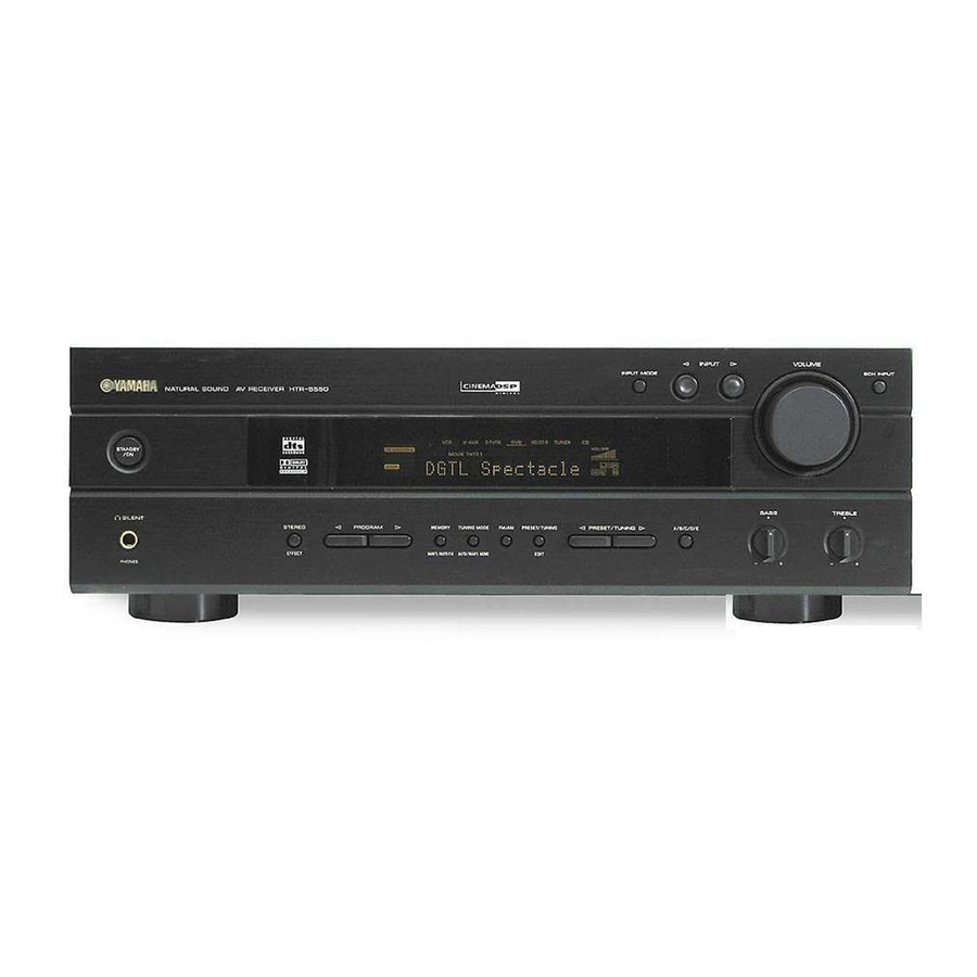
Page 8: Controls And Functions
CONTROLS AND FUNCTIONS Front panel NATURAL SOUND AV RECEIVER STANDBY SILENT STEREO EFFECT PHONES STANDBY/ON Turns this unit on, or set it to the standby mode. When you turn this unit on, you will hear a click and there will be a 4 to 5-second delay before this unit can reproduce sound. - Page 9 SILENT (PHONES jack) Allows you enjoy DSP effect for private listening with headphones. When you connect headphones, no signals are output to the speakers. STEREO/EFFECT Switches between normal stereo and DSP effect reproduction. When STEREO is selected, 2-channel signals are directed to the main left and right speakers without effect sounds and all Dolby Digital and DTS signals (except the LFE channel) are mixed down to the main left and right speakers.
-
Page 10: Remote Control
CONTROLS AND FUNCTIONS Remote control This section describes the remote control controls and their functions. Make sure that the AMP mode is selected before starting operation. See “REMOTE CONTROL FEATURES” on pages 46 to 48. CODE SET TRANSMIT POWER POWER STANDBY MD/CD-R TUNER... -
Page 11: Using The Remote Control
MUTE Mutes the sound. Press again to restore the audio output to the previous volume level. STEREO/EFFECT Switches between normal stereo and DSP effect reproduction. When STEREO is selected, 2-channel signals are directed to the main left and right speakers without effect sounds and all Dolby Digital and DTS signals (except the LFE channel) are mixed down to the main left and right speakers. -
Page 12: Front Panel Display
CONTROLS AND FUNCTIONS Front panel display MATRIX VIRTUAL DIGITAL SILENT PRO LOGIC 1 Processor indicators Lights up when the t, g, VIRTUAL, or MATRIX are activated. PRO LOGIC Input source indicator Shows the current input source with a cursor. MUTE indicator Flashes while the MUTE function is on. -
Page 13: Preparation
LFE (low-frequency effect) channel with high fidelity when playing back Dolby Digital or DTS signals. The YAMAHA Active Servo Processing Subwoofer System is ideal for natural and lively bass reproduction. SPEAKER SETUP... -
Page 14: Connecting The Speakers
SPEAKER SETUP Connecting the speakers Be sure to connect the left channel (L), right channel (R), “+” (red) and “–” (black) properly. If the connections are faulty, no sound will be heard from the speakers, and if the polarity of the speaker connections is incorrect, the sound will be unnatural and lack bass. - Page 15 I SUBWOOFER jack When using a subwoofer with built-in amplifier, including the YAMAHA Active Servo Processing Subwoofer System, connect the input jack of the subwoofer system to this jack. Low bass signals distributed from the main, center and/or rear channels are directed to this jack in accordance with your SPEAKER SET selections. The LFE (low-frequency effect) signals generated when Dolby Digital or DTS is decoded are also directed to this jack in accordance with your SPEAKER SET selections.
-
Page 16: Impedance Selector Switch
SPEAKER SETUP I IMPEDANCE SELECTOR switch WARNING Do not change setting of the IMPEDANCE SELECTOR switch when the power of this unit is on, this may damage the unit. If this unit fails to turn on when STANDBY/ON (or SYSTEM POWER) is pressed, the IMPEDANCE SELECTOR switch may not be fully slid to either position. -
Page 17: Connections
(such as a tape deck, MD recorder and CD player or changer), connect them to the jack with the same number labels as !, #, $ etc. YAMAHA applies this labeling system to all its products. • After you have completed all connections, check them again to make sure they are correct. -
Page 18: Connecting Video Components
CONNECTIONS Connecting video components Refer to the connection examples on the next page. I Types of video jacks There are three types of video jacks as follows: COMPONENT VIDEO S VIDEO VIDEO VIDEO jack Conventional composite video signal. S VIDEO jack Transmits color and luminance separately and achives high-quality color reproduction. - Page 19 AUDIO AUDIO VIDEO INPUT OUTPUT OUTPUT DIGITAL 6CH INPUT AUDIO VIDEO INPUT MAIN S VIDEO V-AUX SURROUND COAXIAL CENTER OPTICAL WOOFER D-TV/CBL D-TV MD/CD-R /CBL (PLAY) /CD-R (REC) MD/CD-R WOOFER OPTICAL S VIDEO DIGITAL MONITOR OUT AUDIO OUTPUT OUTPUT OPTICAL OUTPUT indicates signal direction indicates left analog cables...
-
Page 20: Connecting Audio Components
CONNECTIONS Connecting audio components I Connecting a CD player Connect the coaxial digital output jack on your CD player to the DIGITAL INPUT CD jack. • The AUDIO jacks are available for a CD player which does not have coaxial digital output jack. I Connecting a CD recorder or MD recorder Connect the optical digital signal input jack on your CD... -
Page 21: Connecting The Antennas
Unit: mm (inch) reception than an indoor one. If you experience poor reception quality, an outdoor antenna may improve the quality. Consult the nearest authorized YAMAHA dealer or service center about the outdoor antennas. FREQUENCY STEP switch (China and General models) -
Page 22: Connecting An External Decoder
CONNECTIONS Connecting an external decoder This unit is equipped with 6 additional input jacks (MAIN left and right, CENTER, SURROUND left and right and SUBWOOFER) for discrete multi-channel input from an external decoder, sound processor, or pre-amplifier. Connect the output jacks on your external decoder to the 6CH INPUT jacks. -
Page 23: Turning On The Power
Turning on the power When all connections are complete, turn on the power of this unit. NATURAL SOUND AV RECEIVER STANDBY SILENT STEREO PROGRAM MEMORY TUNING MODE FM/AM PRESET/TUNING PRESET/TUNING EFFECT MAN'L/AUTO FM AUTO/MAN'L MONO EDIT PHONES CODE SET TRANSMIT SYSTEM POWER POWER... -
Page 24: Speaker Mode Settings
SPEAKER MODE SETTINGS This unit has 5 SPEAKER SET items on the SET MENU that you must set according to the number of speakers in your configuration and their size. The following table summarizes these SPEAKER SET items, and shows the initial settings as well as other possible settings. -
Page 25: Adjusting Speaker Output Levels
ADJUSTING SPEAKER OUTPUT LEVELS This section explains how to adjust speaker output levels using the test tone generator. When this adjustment is complete, the output level heard at the listening position should be the same from each speaker. This is important for best performance of the digital sound field processor, and the various decoders (Dolby Digital, Dolby Pro Logic, Dolby Pro Logic... - Page 26 ADJUSTING SPEAKER OUTPUT LEVELS Adjust the level of the effect speakers using j / i so that it matches the level of the main speakers. While adjusting, the test tone is heard from the selected speaker. Note • To adjust the level of the main speakers, use VOLUME knob (or VOLUME +/–...
-
Page 27: Basic Playback
INPUT M0DE NATURAL SOUND AV RECEIVER STANDBY SILENT STEREO PROGRAM MEMORY TUNING MODE FM/AM PRESET/TUNING PRESET/TUNING EFFECT MAN'L/AUTO FM AUTO/MAN'L MONO EDIT PHONES CODE SET TRANSMIT SYSTEM POWER POWER STANDBY POWER MD/CD-R TUNER SLEEP D-TV/CBL V-AUX 6CH INPUT TV VOL TV CH VOLUME –... - Page 28 BASIC PLAYBACK Start playback or select a broadcast station on the source component. Refer to the operation instructions for the component. Adjust the volume to the desired level. The volume level is displayed digitally. Example: –70 dB Control range: VOLUME MUTE (minimum) to 0 dB (maximum) The volume level indicator also shows the current volume level as a bar graph.
-
Page 29: Input Modes And Indications
Input modes and indications This unit comes with a variety input jacks. You can select the type of input signals you desire. Each time you turn on the power of this unit, the input mode is set according to “8 INPUT MODE” setting on the SET MENU (see page 45 for details). -
Page 30: Selecting A Sound Field Program
BASIC PLAYBACK Selecting a sound field program You can enhance your listening experience by selecting a DSP program. For details about each program, see pages 29 to 33. NATURAL SOUND AV RECEIVER STANDBY SILENT STEREO PROGRAM MEMORY TUNING MODE FM/AM PRESET/TUNING PRESET/TUNING EFFECT... - Page 31 I Selecting PRO LOGIC You can enjoy the 2-channel sources decoded into five discrete channels by selecting PRO LOGIC No. 9. NATURAL SOUND AV RECEIVER STANDBY SILENT STEREO PROGRAM MEMORY TUNING MODE FM/AM PRESET/TUNING PRESET/TUNING EFFECT MAN'L/AUTO FM AUTO/MAN'L MONO EDIT PHONES PROGRAM l / h...
-
Page 32: Normal Stereo Reproduction
BASIC PLAYBACK I Playing Dolby Digital Surround EX or DTS ES software Press MATRIX 6.1 to turn on the Dolby Digital + Matrix 6.1 or DTS + Matrix 6.1 decoder. MATRIX V-AUX MATRIX 6.1 DIGITAL MOVIE THTR 1 S p e c t a c l e 6 . 1 The MATRIX indicator lights up. -
Page 33: Digital Sound Field Processing (Dsp)
The traditional stereo system that uses only two speakers is not capable of recreating a realistic sound field. YAMAHA’s DSP requires three effect speakers to recreate sound fields based on the measured sound field data. The processor controls the strength and delay time of the signals output from the three effect speakers to localize the virtual sound sources and fully encompass the listener. -
Page 34: Cinema-Dsp
CINEMA-DSP is an upgraded version of YAMAHA DSP specially designed for movie soundtracks. CINEMA-DSP integrates the DTS, Dolby Digital, and Dolby Pro Logic surround sound technologies with YAMAHA DSP sound field programs to provide a surround sound field. It recreates comprehensive movie sound design in your audio room. In CINEMA-DSP sound field programs, YAMAHA’s exclusive DSP processing is added to the Main left and right, and... -
Page 35: Dolby Pro Logic
Dolby Surround software into 5 discrete full-range channels (3 channels in front and 2 channels in rear). There are 2 modes; MOVIE for movies and MUSIC for 2-channel audio sources. These programs use YAMAHA’s tri-field DSP processing on each of the Dolby Digital or DTS signals for the front, left surround, and right surround channels. -
Page 36: Cinema-Dsp Programs
CINEMA-DSP CINEMA-DSP programs I For movie programs: No. 7 to 9 This unit automatically chooses the appropriate decoder and DSP sound field pattern according to the input signal format. Table of Program Names for Each Input Format Input 2 channel Stereo Program MOVIE... - Page 37 The following list gives you a brief description of the sound fields produced by each of the DSP programs. Keep in mind that most of these are precise digital recreations of actual acoustic environments. Select the DSP program that you feel sounds best regardless of the name and description given for it below.
-
Page 38: Tuning
Automatic and manual tuning There are 2 ways to tune; automatic and manual. Automatic tuning is effective when station signals are strong and there is no interference. I Automatic tuning NATURAL SOUND AV RECEIVER STANDBY SILENT STEREO PROGRAM MEMORY TUNING MODE FM/AM PRESET/TUNING PRESET/TUNING... -
Page 39: Presetting Stations
Presetting stations I Automatically presetting stations (for FM stations) You can use the automatic preset tuning feature to store FM stations. This function enables this unit to automatically tune in to FM stations with strong signals, and to store up to 40 (8 stations x 5 groups) of those stations in order. - Page 40 TUNING I Manually presetting stations You can also store up to 40 stations (8 stations x 5 groups) manually. NATURAL SOUND AV RECEIVER STANDBY SILENT STEREO PROGRAM FM/AM PRESET/TUNING PRESET/TUNING MEMORY TUNING MODE EFFECT MAN'L/AUTO FM AUTO/MAN'L MONO EDIT PHONES Tune in to a station.
-
Page 41: Tuning In To A Preset Station
Tuning in to a preset station You can tune any desired station simply by selecting the preset station number under which it was stored. INPUT M0DE NATURAL SOUND AV RECEIVER STANDBY SILENT STEREO PROGRAM MEMORY TUNING MODE FM/AM PRESET/TUNING PRESET/TUNING EFFECT MAN'L/AUTO FM AUTO/MAN'L MONO... -
Page 42: Sleep Timer
Use this feature to automatically set this unit in the standby mode after the amount of time you have set. The sleep timer is useful when you are going to sleep while this unit is playing or recording a source. The sleep timer also automatically turns off the external component(s) connected to AC OUTLET(S). -
Page 43: Recording
Recording adjustments and other operations are performed from the recording components. Refer to the operation instructions for these components. NATURAL SOUND AV RECEIVER STANDBY SILENT STEREO PROGRAM MEMORY TUNING MODE FM/AM PRESET/TUNING PRESET/TUNING EFFECT MAN'L/AUTO FM AUTO/MAN'L MONO EDIT PHONES CODE SET TRANSMIT SYSTEM... -
Page 44: Advanced Operation
ADVANCED OPERATION The SET MENU consists of 10 items including the speaker mode setting. Choose the appropriate item and adjust or select the values as necessary. • You can adjust the items on the SET MENU while playing a source. Items 1 SPEAKER SET A CENTER... -
Page 45: Speaker Set (Speaker Mode Settings)
Press j / i repeatedly to change the setting of the – item. Press u/d repeatedly until the menu disappears or simply press one of the DSP program group buttons to exit SET MENU. PRESET/CH HALL SPORTS – SELECT /DTS SUR. - Page 46 SET MENU I 1B MAIN (main speaker mode) Choices: LARGE, SMALL LARGE Select this if you have large main speakers. The entire range of the main left and right channel signal is directed to the main left and right speakers. SMALL Select this if you have small main speakers.
-
Page 47: Lfe Level
2 LFE LEVEL Use this feature to adjust the output level of the LFE (low-frequency effect) channel when playing back a Dolby Digital or DTS signal. The LFE signal carries the low-frequency special effect sound which is only added to certain scenes. -
Page 48: Range (Dynamic Range)
SET MENU 4 D. RANGE (dynamic range) Use this feature to adjust the dynamic range. This setting is effective only when this unit is decoding Dolby Digital signals. Choices: MAX, STD (standard), MIN (minimum) Select the “MAX” for feature films. Select the “STD”... -
Page 49: Input Mode (Initial Input Mode)
8 INPUT MODE (initial input mode) Use this feature to designate the input mode for sources connected to the DIGITAL INPUT jacks when you turn on this unit (see page 25 for details about the input mode). Choices: AUTO, LAST AUTO Select this to allow this unit to automatically detect the type of input signal and select the appropriate input mode. -
Page 50: Remote Control Features
REMOTE CONTROL FEATURES In addition to controlling this unit, the remote control can operate other A/V components made by YAMAHA and other manufacturers. To control other components, you must set up the remote control with the manufacturer codes. Control area... -
Page 51: Setting The Manufacturer Code
I Clearing setup manufacturer code for the component control Press an input selector button or Å/ı to select the component control for which you want to clear the manufacturer code. Code YAMAHA 0005 YAMAHA 0024 YAMAHA 0003 YAMAHA 0098 Press CODE SET by using a ballpoint pen or –... -
Page 52: Controlling Other Components
REMOTE CONTROL FEATURES Controlling other components You can operate other components when you have set the manufacturer code for your component. Note, however, that some buttons may not operate your component. Once you select an input source, the remote control switches to the mode for operating the component. -
Page 53: Adjusting The Level Of The Effect Speakers
ADJUSTING THE LEVEL OF THE EFFECT SPEAKERS You can adjust the output level of each effect speaker (center, rear left and right, and subwoofer) while listening to a source. Adjustment should be made with the remote control. CODE SET TRANSMIT SYSTEM POWER POWER... -
Page 54: Adjusting The Delay Time
ADJUSTING THE DELAY TIME You can adjust the time difference between the beginning of the sound from the main speakers and the beginning of the sound effect from the rear speakers. The larger the value, the later the sound effect is generated. The delay time can be individually adjusted to all DSP programs. -
Page 55: Adjusting The Parameter Settings For Pro Logic Music
ADJUSTING THE PARAMETER SETTINGS FOR PRO LOGIC Changing parameter settings You can adjust the values of PRO LOGIC parameters so the sound fields are recreated accurately in your listening room. Adjustments should be made with the remote control. TRANSMIT CODE SET SYSTEM POWER POWER... -
Page 56: Troubleshooting
Refer to the chart below when this unit does not function properly. If the problem you are experiencing is not listed below or if the instruction below does not help, set this unit to the standby mode, disconnect the power cord, and contact the nearest authorized YAMAHA dealer or service center. I General... - Page 57 Problem The sound suddenly The protection circuit has been activated goes off. because of a short circuit, etc. The sleep timer has functioned. The sound is muted. Only the speaker on Incorrect cable connections. one side can be heard. Incorrect setting of “5 L/R BALANCE” on the SET MENU.
- Page 58 TROUBLESHOOTING Problem A “humming” sound Incorrect cable connections. can be heard. The volume level The component connected to the OUT cannot be increased, or (REC) jacks of this unit is turned off. the sound is distorted. The sound effect It is not possible to record the sound cannot be recorded.
- Page 59 I Tuner Problem FM stereo reception is The characteristics of FM stereo noisy. broadcasts may cause this problem when the transmitter is too far away or the antenna input is poor. There is distortion, and There is multipath interference. clear reception cannot be obtained even with a good FM antenna.
-
Page 60: Glossary
Based on a wealth of actually measured data, YAMAHA CINEMA DSP uses YAMAHA original sound field technology to combine Dolby Pro Logic, Dolby Digital and DTS systems to provide the visual and audio experience of movie theater in the listening room of your own home. -
Page 61: Virtual Cinema Dsp
I Virtual CINEMA DSP YAMAHA has developed a virtual CINEMA DSP algorithm that allows you to enjoy DSP sound field surround effects even without any rear speakers by using virtual rear speakers. It is even possible to enjoy virtual CINEMA DSP using a minimal 2-speaker system that does not include a center speaker. -
Page 62: Specifications
AUDIO SECTION • Minimum RMS Output Power for Main, Center, Rear 20 Hz to 20 kHz, 0.06% THD, 8 Ω [U.S.A. and Canada models] ... 75 W [Other models] ... 65 W 1 kHz, 0.06% THD, 8 Ω [U.S.A. and Canada models] ... 80 W [Other models] ... - Page 63 LIST OF MANUFACTURER CODES LISTE DES CODES DES FABRICANTS ELECTRON ELIN A TANDY 0941 ELTA ABEX 1151 EMERSON ADMIRA 1141 ADVENTURA 1131 AIKO 1121 AIWA 1481 AKAI 0331, 1101, 1111 ALBA 0431 ALLERON 1091 AMBASSADOR 1081 ENVISION AMSTRAD 0481, 1081 ERRES ANAM 0251, 1041, 1051,...
- Page 64 0971, 0991, 1031, PULSAR 1091, 1111, 1771 RCA DIGITAL SATELLITE WATSON 1001 SYSTEM XOGEGO 1611, 1621, 1661, REALISTIC 1741, 1761 REGENCY/EASTERN 0686 YAMAHA 0361, 1031, 1111 RUNCO YOKO 1001 SAMSUNG ZENITH 0011, 0041, 0891, SCIENTIFIC ATLANTA 175/475 0991, 1771 ZONDA 1161...
-
Page 65: Dvd Player
0392, 0412, 0932 PENNY 0202, 0432, 0602, 0632, 0692, 0912, WARDS 0922, 0932 PENTAX 0592, 0602 PERDIO 0992 PHILCO 0002, 0932 YAMAHA PHILIPS 0002, 0282, 0402, ZENITH 0492, 0932 PILOT 0912 DVD PLAYER PIONEER 0442, 0542 PROSCAN 1002, 1012, 1022,... - Page 66 0034, 0064, 0204, 0334 ONKYO 0364, 0374 PHILIPS 0094 PIONEER 0034, 0044, 0064 REVOX 0354 SANSUI 0094, 0344 SHARP 0264 SHERWOOD 0334 SONY 0054, 0084, 0324 TEAC 0194, 0254 TECHNICS 0074, 0314 WARDS 0034 YAMAHA 0004, 0014, 0104, 0114, 0164, 0174, 0264...
- Page 67 YAMAHA ELECTRONIQUE FRANCE S.A. RUE AMBROISE CROIZAT BP70 CROISSY-BEAUBOURG 77312 MARNE-LA-VALLEE CEDEX02, FRANCE YAMAHA ELECTRONICS (UK) LTD. YAMAHA HOUSE, 200 RICKMANSWORTH ROAD WATFORD, HERTS WD1 7JS, ENGLAND YAMAHA SCANDINAVIA A.B. J A WETTERGRENS GATA 1, BOX 30053, 400 43 VÄSTRA FRÖLUNDA, SWEDEN Printed in Malaysia V874620-1 YAMAHA MUSIC AUSTRALIA PTY, LTD.